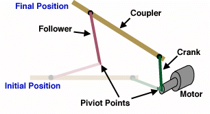
Introduction:This handout will take you through the steps of designing a 4 bar linkage. A four bar linkage is used to define and constrain the motion of an object to a particular path. The four bars of the linkage are as follows.
|
|
Step 1 | Step 2 | Step 3 | Step 4 | Jamming
Introduction:This handout will take you through the steps of designing a 4 bar linkage. A four bar linkage is used to define and constrain the motion of an object to a particular path. The four bars of the linkage are as follows.
|
|
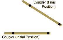
Note: All drawings show both the inital and final positions of linkages.
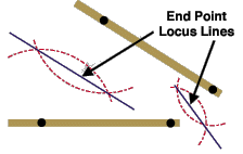
Draw arcs from each mounting point on the output bar. The radius of the arcs should be the same for each mounting hole.
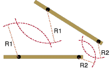
Draw a pair of lines, one connecting the intersections of each pair of arcs. These lines represent the locus of possible end points for the connecting links.
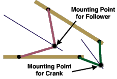
Draw in the connecting bars. There are many possible location for the mounting point on connecting bars. The two figures below show equally valid possibilities for the location of the connecting bars in this example. The initial and final positions of all bars are shown.
|
or
|
|
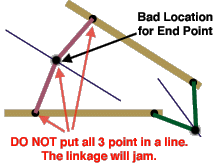
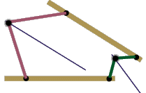
To prevent the linkage from jamming, the mounting point for the connecting bars should not be placed in line with the output bar's mounting hole's initial and final positions. See figure below.