
Code_Aster
®
Version
7.4
Titrate:
Calculation of the characteristics of a beam of cross section unspecified
Date:
01/09/05
Author (S):
J.M. PROIX, NR. LAURENT, P. HEMON, G. BERTRAND
Key:
R3.08.03-C
Page
:
1/42
Manual of Reference
R3.08 booklet: Machine elements with average fiber
HT-66/05/002/A
Organization (S):
EDF-R & D/AMA, IAT St CYR, CS-SI
Manual of Reference
R3.08 booklet: Machine elements with average fiber
Document: R3.08.03
Calculation of the characteristics of a beam of section
unspecified transversal
Summary:
One presents the principle of the calculation of the various sizes characteristic of the sections of beams. Those
are established starting from the geometrical characteristics of the cross section of the beam.
These values are to be provided to the operand
SECTION: “GENERAL”
of the operator
AFFE
_
CARA
_
ELEM
[U4.42.01].
To determine them, of the numerical methods are presented, and implemented in the control
MACR_CARA_POUTRE
.
In the case of sections
“RIGHT-ANGLED”
and
“CIRCLE”
, one calculates directly in
AFFE_CARA_ELEM
characteristics using simplified formulas which one clarifies here.

Code_Aster
®
Version
7.4
Titrate:
Calculation of the characteristics of a beam of cross section unspecified
Date:
01/09/05
Author (S):
J.M. PROIX, NR. LAURENT, P. HEMON, G. BERTRAND
Key:
R3.08.03-C
Page
:
2/42
Manual of Reference
R3.08 booklet: Machine elements with average fiber
HT-66/05/002/A
Count
matters
Appendix 1
Determination of the constant of torsion for sections has borders
Appendix 2
Determination of the constant of shearing of a beam equivalent to one
Code_Aster
®
Version
7.4
Titrate:
Calculation of the characteristics of a beam of cross section unspecified
Date:
01/09/05
Author (S):
J.M. PROIX, NR. LAURENT, P. HEMON, G. BERTRAND
Key:
R3.08.03-C
Page
:
3/42
Manual of Reference
R3.08 booklet: Machine elements with average fiber
HT-66/05/002/A
1
Geometrical characteristics
Assumption:
One treats here only the cross sections of homogeneous and isotropic beams (same
material characteristics for all the points and in all the directions). The control
MACR_CARA_POUTRE
can also calculate the geometrical characteristics of a whole of sections
disjoined.
1.1 Section
unspecified
1.1.1 Principle
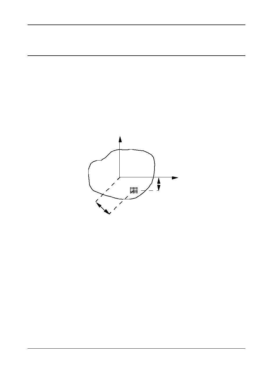
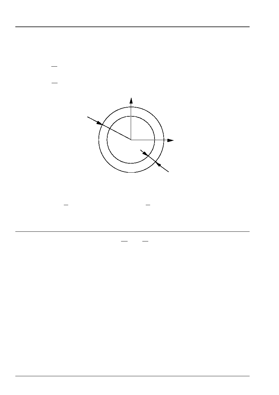
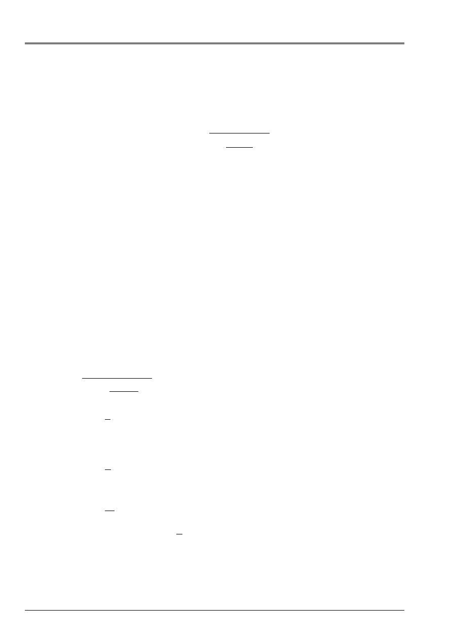
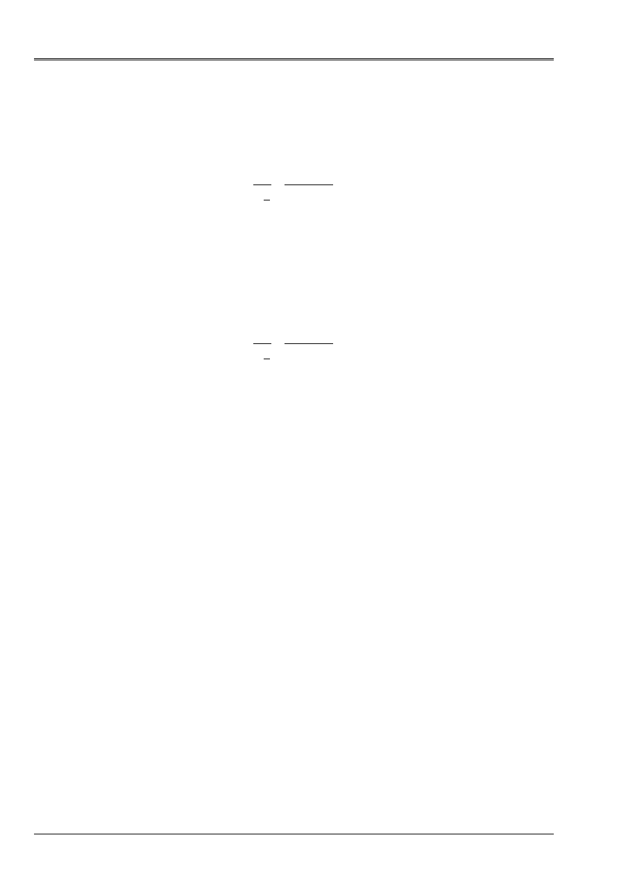
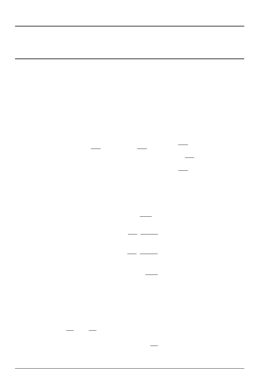
That is to say a section (S) of surface S in the plan (0, y, Z) whose origin O is the center of gravity G of
section, [Figure 1.1.1-a].
Z
R
Z
O
G
(S)
y
Appear 1.1.1-a: section in plan (0, y, Z)
Geometrical moment of inertia of (S) compared to the axis (OY) (which passes by the center of gravity)
express yourself by:
[]
I
Z dS
I
dS
y
S
S
=
with
=
2
OM
OM
One defines in a similar way the geometrical moment compared to (O
Z
) by:
I
y dS
Z
S
=
2
When centrifugal geometrical moment (often called produced inertia of surface) defined by
I
y Z dS
yz
S
=
is null, the axes (OY) and (O
Z
) are main axes of the section (S). One
place for the continuation on this assumption;
I
y
and
I
Z
are then called the geometrical moments
main.
Code_Aster
®
Version
7.4
Titrate:
Calculation of the characteristics of a beam of cross section unspecified
Date:
01/09/05
Author (S):
J.M. PROIX, NR. LAURENT, P. HEMON, G. BERTRAND
Key:
R3.08.03-C
Page
:
4/42
Manual of Reference
R3.08 booklet: Machine elements with average fiber
HT-66/05/002/A
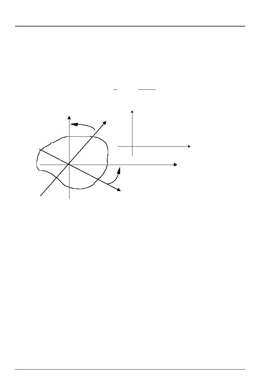
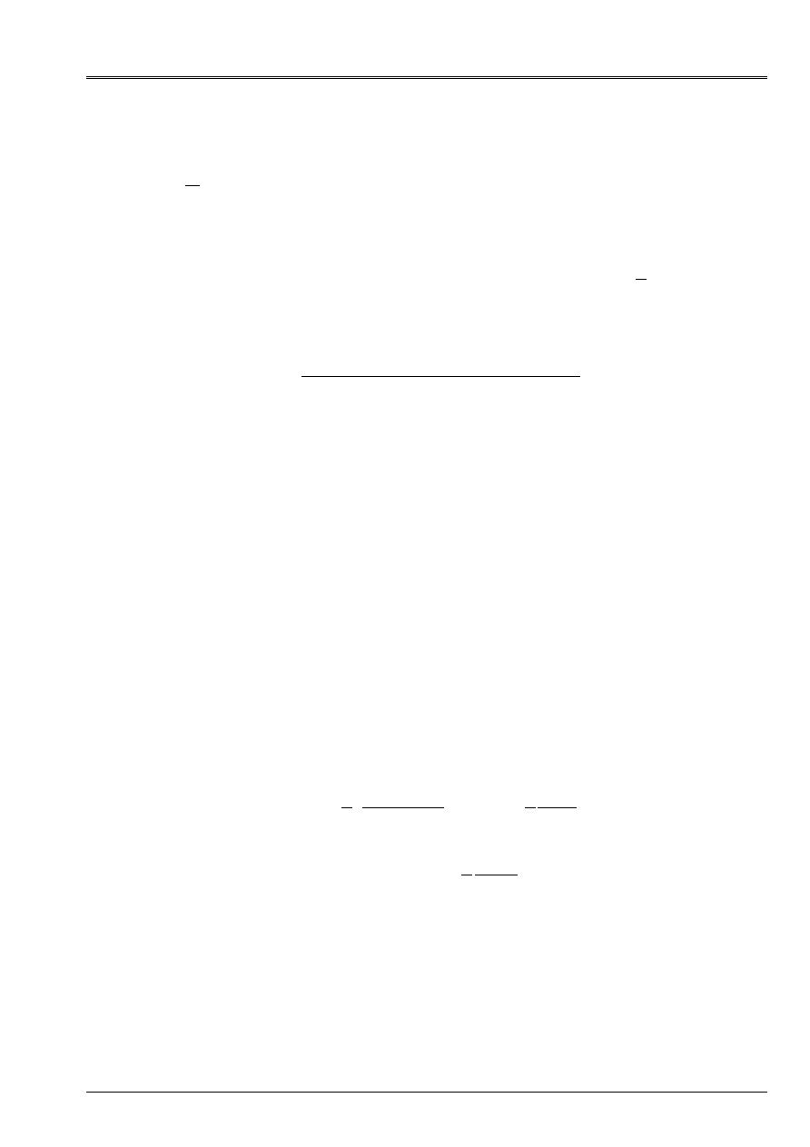
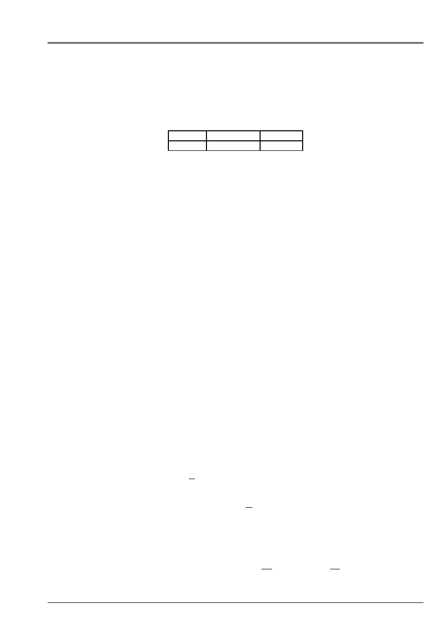
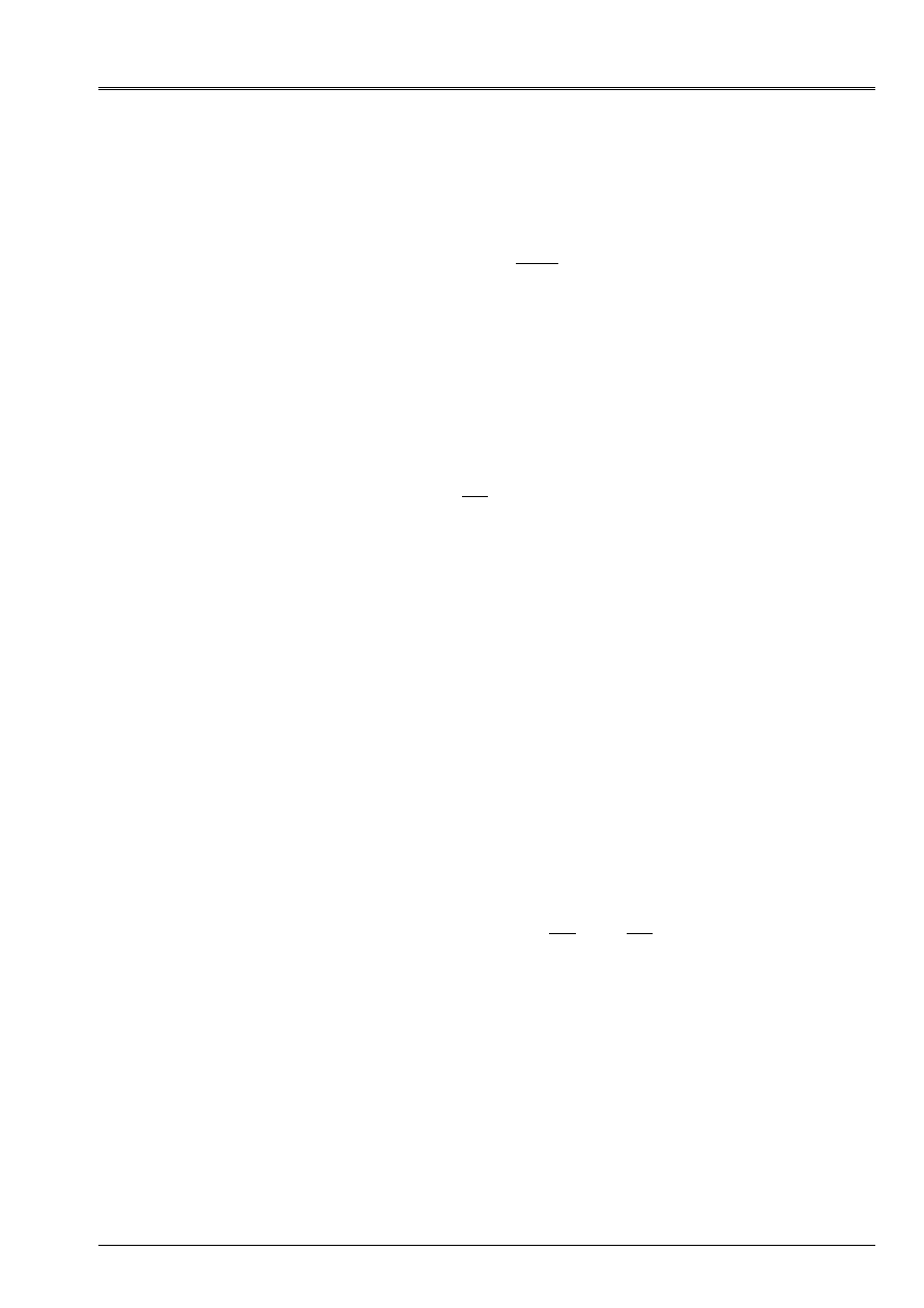
Generally, we must place ourselves in the main axes of a section of beam
for all that relates to its characteristics since the elements of beam of Code_Aster are
formulated in this reference mark. On the basis of an origin located at the center of gravity, it is enough, to pass from one
unspecified system of axes (G, y', z') to the system of principal axes (G, y, Z), to carry out a rotation
of angle
such as [Figure 1.1.1-b]:
=
''
'
1
2
2
Arctg
'
I
I
I
y Z
Z
y
-
Z
y
G
z'
y'
(G, y, Z) main Axes
(G, y', z') unspecified Axes
P
y
Z
Appear 1.1.1-b: main and unspecified Axes
The polar geometrical moment compared to the center of gravity is given by:
I
R dS
p
S
=
2
where R is the distance from the element dS in the center of gravity [Figure 1.1.1-a].
One deduces some naturally
I
I
I
p
y
Z
= +
The polar geometrical moment intervenes in the calculation of the rigidity of torsion of the beams of section
circular (torsion of Coming Saint). For the other forms of sections, one will define a constant of
of the same torsion dimension.
Moreover, the geometrical moments can be calculated in another reference mark (P, y, Z), of origin P
unspecified different from the center of gravity G (formula of Huygens):
(
)
(
)
I
I
S
Z dS
S
y
y
S
P
G
=
+
=
+
GP.Z
GP.Z
2
2
2
.
.
(
)
(
)
I
I
S
y dS
Y
S
Z
Z
S
P
G
=
+
=
+
GP. Y
GP.
2
2
2
.
.
(
) (
)
(
) (
)
I
I
S
yz dS
S
yz
yz
S
P
G
=
+
=
+
GP. Y GP.Z
GP. Y GP.Z
.
.
Code_Aster
®
Version
7.4
Titrate:
Calculation of the characteristics of a beam of cross section unspecified
Date:
01/09/05
Author (S):
J.M. PROIX, NR. LAURENT, P. HEMON, G. BERTRAND
Key:
R3.08.03-C
Page
:
5/42
Manual of Reference
R3.08 booklet: Machine elements with average fiber
HT-66/05/002/A
in a general way, the formula of Huygens gives:
[]
(
) (
)
(
)
I
S
S
S
S
S
S
=
+
+
=
+
+
=
+
PG GM
PG GM
PG
PG
GM
GM
PG
GM
PG
PG
GM
GM
2
1.1.2 Calculation of the geometrical characteristics using
MACR_CARA_POUTRE
This macro-control allows the determination of the characteristics of a cross section of
beam starting from a mesh 2D of the section [U4.42.02]. It makes it possible to build a table of
values, usable in the control
AFFE_CARA_ELEM
(
SECTION
:
“GENERAL”
[U4.42.01]).
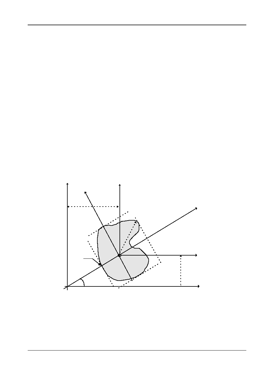
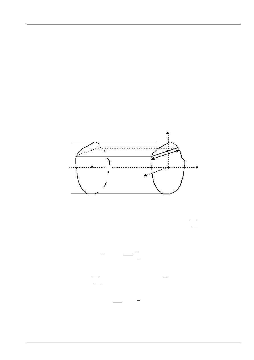
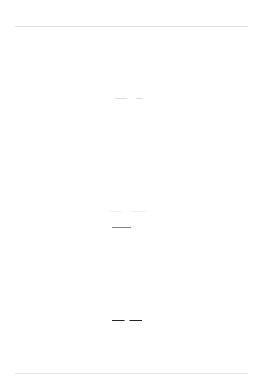
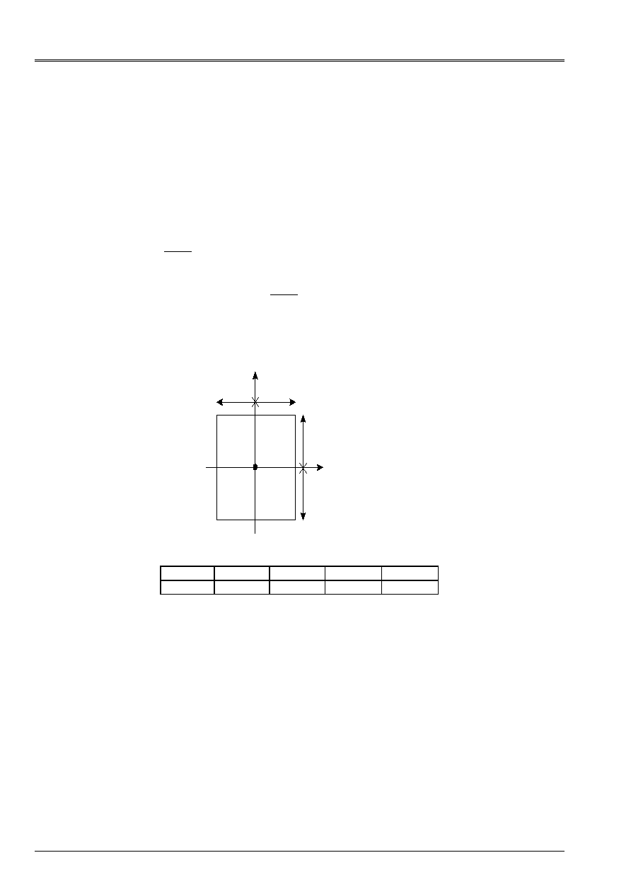
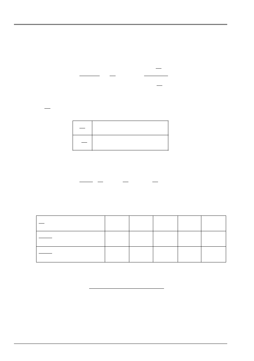
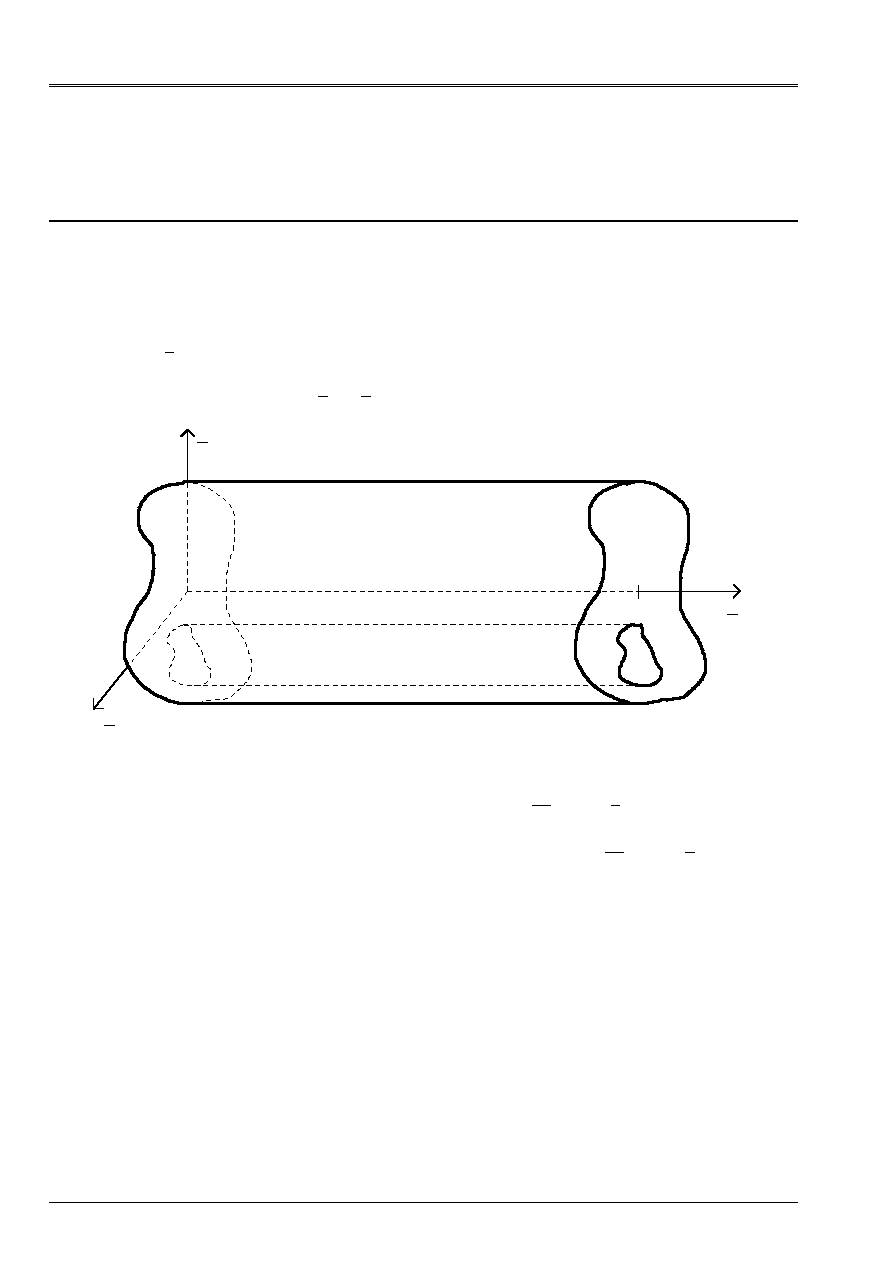
The geometrical characteristics can be calculated on the complete mesh, half mesh with
symmetry compared to X or with Y, quarter of mesh with two symmetries compared to X and with Y
[Figure 1.1.2-a].
These characteristics are calculated in the table for all the mesh and each group of
meshs of the list specified by the user (case of a network of beams).
The data correspond to a half or a quarter of the section if the key words
SYME_X
or
SYME_Y
are present.
G
X
Y
Z_MIN
y (main)
R_MAX
Z_MAX
ALPHA
X
CDG_Y
CDG_X
Y
O
Z (main)
Y_MIN
Y_MAX
Appear 1.1.2-a: Definition of the geometrical characteristics

Code_Aster
®
Version
7.4
Titrate:
Calculation of the characteristics of a beam of cross section unspecified
Date:
01/09/05
Author (S):
J.M. PROIX, NR. LAURENT, P. HEMON, G. BERTRAND
Key:
R3.08.03-C
Page
:
6/42
Manual of Reference
R3.08 booklet: Machine elements with average fiber
HT-66/05/002/A
The results are gathered in four groups:
1) In the reference mark
OXY
of description of the mesh 2D for the mesh provided by the user
·
surface:
AIRE_M
·
position of the center of gravity:
CDG_X_M,
CDG_Y_M
·
moments and product of inertia of surface, in the center of gravity
G
in the reference mark
GXY
:
IX_G_M
,
IY_G_M
,
IXY_G_M
2) In the same total reference mark, for the mesh obtained by symmetrization if
SYME_X
or
SYME_Y
:
·
surface:
SURFACE
·
position of the center of gravity:
CDG_X,
CDG_Y
·
moments and product of inertia of surface, in the center of gravity
G
in the reference mark
GXY
:
IX_G
,
IY_G
,
IXY_G
3) In the main reference mark of inertia
Gyz
. cross-section, whose denomination corresponds to that
used with the description of the elements of neutral fiber beam
Gx
[U4.24.01].
·
main moments of inertia of surface in the reference mark
Gyz
, usable for the calculation of rigidity
of bending of the beam:
IY_PRIN_G
and
IZ_PRIN_G
·
angle of flow of the reference mark
GXY
with the main reference mark of inertia
Gyz
:
ALPHA
·
characteristic distances, compared to the center of gravity
G
section for calculations of
maximum stresses:
Y_MAX
,
Y_MIN
,
Z_MAX
,
Z_MIN
and
R_MAX
.
4) In the total reference mark, in a point P provided by the user:
·
X_P
,
Y_P
: not calculation of the moments of inertia
·
IX_P
,
IY_P
,
IXY_P
: moments of inertia in the reference mark
PXY
·
IY_PRIN_P
,
IZ_PRIN_P
: moments of inertia in the reference mark
Pyz
.
1.1.3 Calculations
carried out
The list of the controls called by
MACR_CARA_POUTRE
is indicated in the document [U4.42.02].
The preceding quantities are obtained by the call to
POST_ELEM
, for the option
“CARA_GEOM”
. Of
more, one can add the key words to it
SYME_X
,
SYME_Y
, and
ORIG_INER
who defines the P. point.
Calculations are carried out in
POST_ELEM
, for all the mesh, then possibly for each
group meshs, in the following way:
1) Loop on the elements 2D (modeling
D_PLAN
), with call of the elementary option
“MASS_INER”
. One is obtained
CHAM_ELEM
with a value by element (1 point of Gauss)
containing the components:
dS
dS
dS
element
element
element
,
,
y
,
X
S
S
S
dS
y dS
dS
X
,
, xy
2
2
2) Summation of the preceding elementary quantities to obtain:
AIRE_M
,
CDG_X_M
,
CDG_Y_M
,
IX_G_M
,
IY_G_M
,
IXY_G_M
3) Calculation
of
SURFACE
,
CDG_X
,
CDG_Y
,
IX_G
,
IY_G
,
IXY_G
(taking into account of
SYME_X
,
SYME_Y
)
4) Calculation
of
IY_PRIN_G
,
IZ_PRIN_G
,
ALPHA
5) Calculation
of
Y_MAX
,
Z_MAX
,
Y_MIN
,
Z_MIN
,
R_MAX
6) If one clarifies a point P particular (key word
ORIG_INER
), one calculates also the characteristics
in the total reference mark of origin P:
PXY
Code_Aster
®
Version
7.4
Titrate:
Calculation of the characteristics of a beam of cross section unspecified
Date:
01/09/05
Author (S):
J.M. PROIX, NR. LAURENT, P. HEMON, G. BERTRAND
Key:
R3.08.03-C
Page
:
7/42
Manual of Reference
R3.08 booklet: Machine elements with average fiber
HT-66/05/002/A
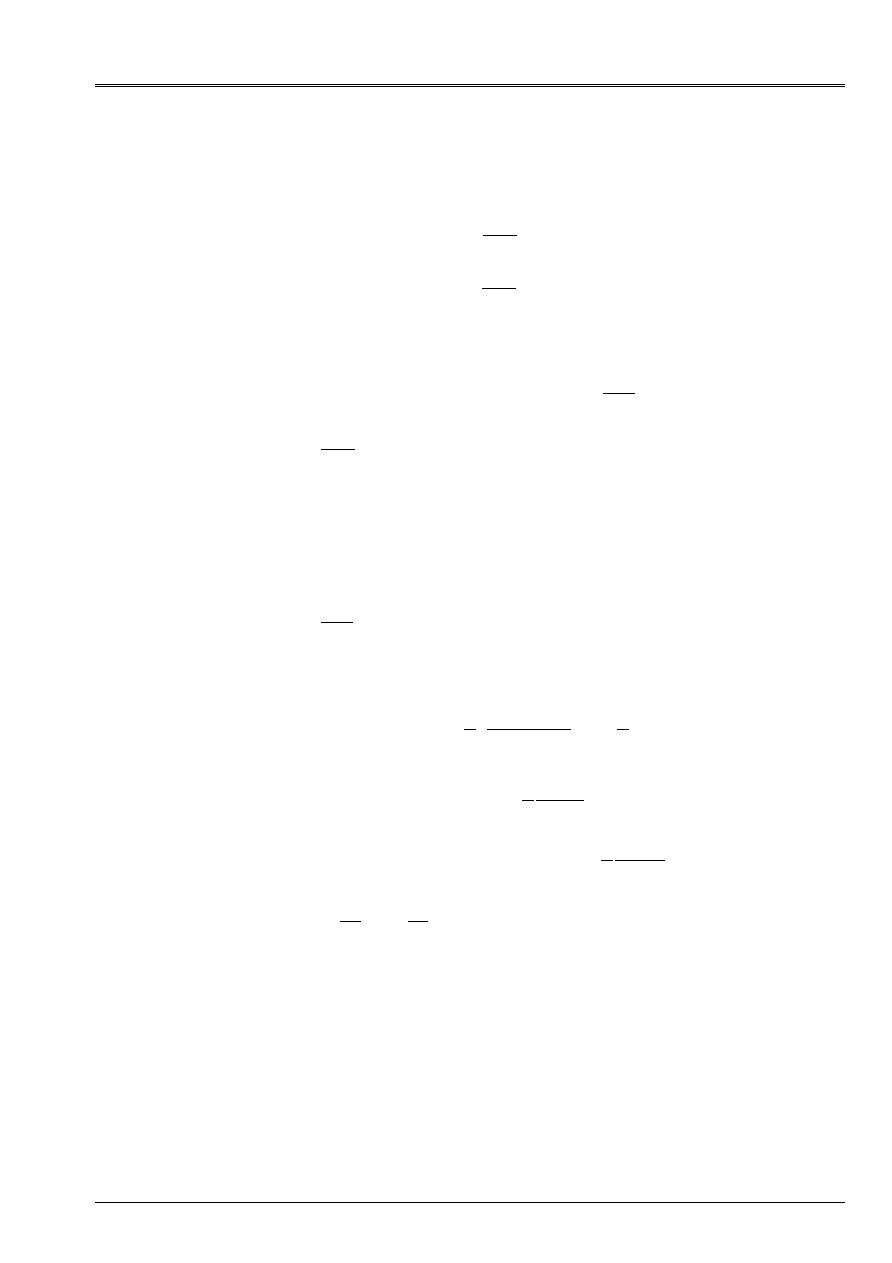
1.1.4 Examples
of use
: Full rectangle (treaty by test ZZZZ105G)
y
B
B
GR2
GR1
H
H
X
0
B = 0.01
H = 0.025
Geometrical characteristics obtained
PLACE AIRE_M
CDG_X_M
CDG_Y_M
IX_G_M
IY_G_M
IXY_G_M
0.000003
1.00E-03
4.24E-18
- 3.39E-18
2.08E-07
3.33E-08
2.65E-23
GR1
5.00E-04
2.20E-17 - 1.25E-02 2.60E-08
1.67E-08
3.97E-23
GR2
5.00E-04
- 8.47E-18 1.25E-02
2.60E-08
1.67E-08
5.62E-23
PLACE
SURFACE
CDG_X CDG_Y IX_G IY_G IXY_G IY_PRIN_G IZ_PRIN_G ALPHA
0.000003 1.00E-03 4.24E-18 - 3.39E-18 2.08E-07 3.33E-08 2.65E-23 3.33E-08 2.08E-07 9.00E+01
GR1
5.00E-04 2.20E-17 - 1.25E-02 2.60E-08 1.67E-08 3.97E-23 1.67E-08 2.60E-08 9.00E+01
GR2
5.00E-04 - 8.47E-18 1.25E-02 2.60E-08 1.67E-08 5.62E-23 1.67E-08 2.60E-08 9.00E+01
PLACE X_P
Y_P IX_P
IY_P
IXY_P
IY_PRIN_P
IZ_PRIN_P
0.000003
0.00E+00 0.00E+00
2.08E-07 3.33E-08
2.65E-23
3.33E-08
2.08E-07
GR1
0.00E+00 0.00E+00
1.04E-07 1.67E-08
- 9.79E-23
1.67E-08
1.04E-07
GR2
0.00E+00 0.00E+00
1.04E-07 1.67E-08
3.31E-24
1.67E-08
1.04E-07
PLACE Y_MAX Z_MAX Y_MIN Z_MIN R_MAX
0.000003
2.50E-02
1.00E-02
- 2.50E-02
1.00E-02
2.69E-02
GR1
1.25E-02
1.00E-02 1.25E-02
1.00E-02
3.36E-02
GR2
- 1.25E-02 - 1.00E-02 - 1.25E-02 - 1.00E-02 3.36E-02
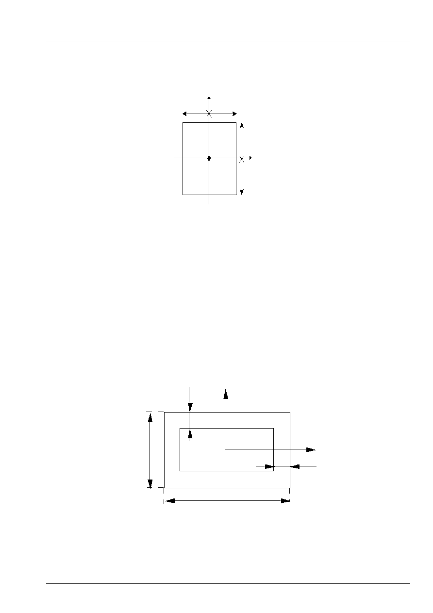
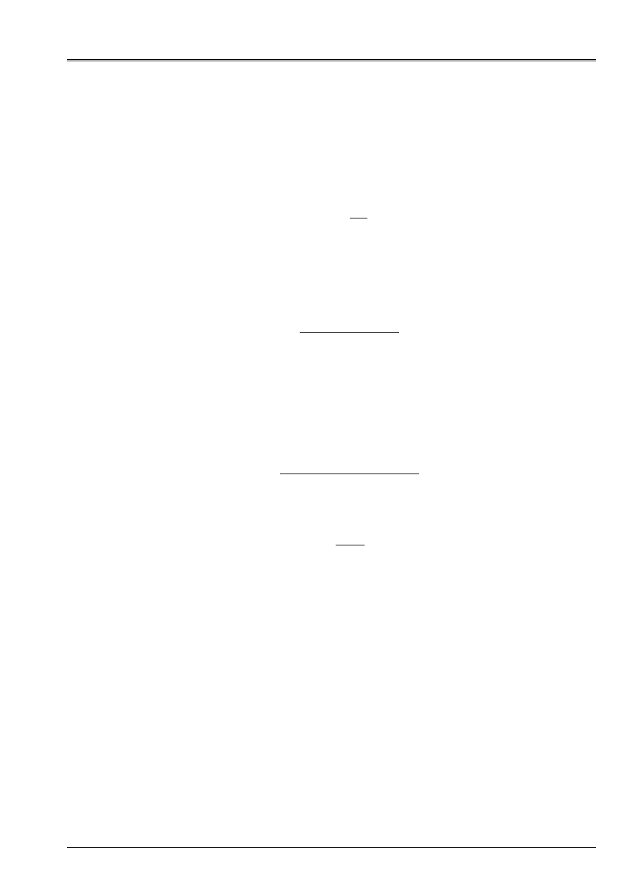
1.2
Particular case of the sections rectangular and circular
The geometrical characteristics are directly calculated in
AFFE_CARA_ELEM
from
data of the user.
y
Z
hy
Hz
epz
epy
G
Appear rectangular 1.2-a: section
Code_Aster
®
Version
7.4
Titrate:
Calculation of the characteristics of a beam of unspecified cross section
Date:
01/09/05
Author (S):
J.M. PROIX, NR. LAURENT, P. HEMON, G. BERTRAND
Key:
R3.08.03-C
Page
:
8/42
Manual of Reference
R3.08 booklet: Machine elements with average fiber
HT-66/05/002/A
In the case of the rectangular beam (Operand
SECTION: “RIGHT-ANGLED”
), calculation gives:
(
)
(
)
[
]
I
y
= 1
12
2
2
3
3
H H
H
ep
H
ep
y
Z
y
y
Z
Z
-
-
-
(
)
(
)
I
H H
H
ep
H
ep
Z
Z
y
Z
Z
y
y
=
1
12
2
2
3
3
-
-
-
y
Z
ep
R
G
Appear circular 1.2-b: section
For the circular section (Operand
SECTION:
“CIRCLE”
), one obtains:
(
)
[
]
(
)
[
]
I
I
R
R
ep
I
R
R
ep
y
Z
p
= =
=
4
2
4
4
4
4
-
-
-
-
2
Coefficients of shearing and the center of shearing
It is a question of evaluating the coefficients
With
K
With
K
y
y
Z
Z
=
=
1
1
,
intervening in the models of beams of
Timoshenko with taking into account of the shearing strains. For the beams of EULER, these
coefficients do not intervene [U4.42.01 §7.4.2] and [R3.08.01 §2.3.1]. These coefficients are obtained
for a linear elastic behavior.
In the case of the unspecified sections, the coefficients of shearing are to be provided by the user
in
AFFE_CARA_ELEM
, if the selected element is a beam of TIMOSHENKO (model
POU_D_T
,
POU_C_T
,
POU_D_TG
and
POU_D_TG_M
).
In the case of the circular or rectangular sections, the coefficients of shearing are calculated
by analytical methods of [§2.1].
In all the cases, they can be calculated by
MACR_CARA_POUTRE
, starting from the plane mesh of
section. The numerical method used is exposed to [§2.3]. This method applies to
unspecified sections (of homogeneous and isotropic material). In appendix 2, one describes an extension of
this method with the case of a network of parallel beams maintained between two rigid floors.
The position of the center of torsion (or shearing centers) is obtained only by methods
numerical (cf [§2.3]). For the rectangular and circular sections, as for all the sections
in 2 symmetry planes, the center of torsion is confused with the center of gravity of the section.
Code_Aster
®
Version
7.4
Titrate:
Calculation of the characteristics of a beam of cross section unspecified
Date:
01/09/05
Author (S):
J.M. PROIX, NR. LAURENT, P. HEMON, G. BERTRAND
Key:
R3.08.03-C
Page
:
9/42
Manual of Reference
R3.08 booklet: Machine elements with average fiber
HT-66/05/002/A
2.1 Methods
analytical
One describes three analytical methods allowing to calculate coefficients of shearing,
applicable to the unspecified sections.
The first two methods differ by the definition which they propose of the coefficient of
shearing, but rest on the same assumption which consists in postulating the form of the distribution
shear stresses in the section.
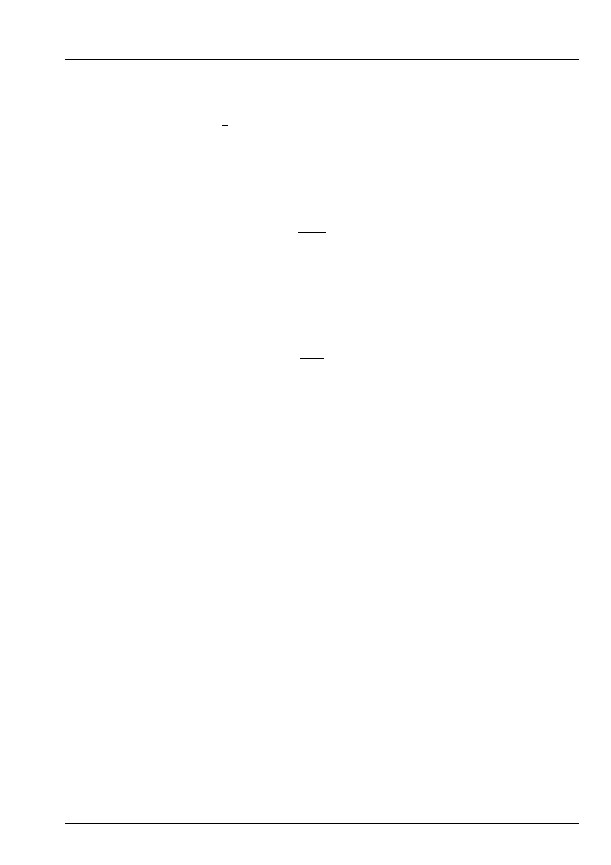
2.1.1 Assumption of distribution of shearings: formulate JOURAWSKI
Let us consider for example the case of a beam of cross-section S, subjected to a sharp effort
V
dS
y
xy
S
=
. One writes the balance of a prismatic part of the beam, ranging between the sections
straight lines
S
X
and
S
x+a
and between the plan of cut located at the ordinate
y
and
y
max
(ref. [bib8]). Efforts
acting on this part of beam are the vectors forced on the faces
S
X
and
S
x+a
, and those
acting on the face located in
y
.
x+a
X
y
max
Z
S
X
S
x+a
y
B (Z)
Appear 2.1.1-a
By applying the theorem of the resultant, one obtains:
(
)
(
)
(
) ()
(
)
xx
S
xx
S
xy
X
X has
X has
X
B y
B y
X y Z Dy dz
X y Z Dy dz
NR X has y
NR X y
y Z D dz
+
-
=
+
-
=
-
+
,
,
,
,
,
()
()
2
2
To evaluate the term of straight line, JOURAWSKI proposed to consider only the average of
shearings according to Z:
() ()
(
)
xy
xy
B
B
X y
B y
X y Z dz
,
,
=
-
1
2
2
then
(
)
()
-
+
+
=
B y
B y
xy
X
X has
xy
X
X has
y Z D dz
B y
y D
()
()
,
()
,
2
2
and while making tend has towards 0,
() ()
NR
X
B y
X y
xy
=
,
Code_Aster
®
Version
7.4
Titrate:
Calculation of the characteristics of a beam of cross section unspecified
Date:
01/09/05
Author (S):
J.M. PROIX, NR. LAURENT, P. HEMON, G. BERTRAND
Key:
R3.08.03-C
Page
:
10/42
Manual of Reference
R3.08 booklet: Machine elements with average fiber
HT-66/05/002/A
The equilibrium equations of beam and the distribution of bending stresses (in elasticity) give:
()
(
)
NR X y
X y Z dydz
M X y
I
dydz
xx
S
Z
Z
S
X
X
,
,
().
=
=
()
=
M X
I
m y
m y
T B T dt
Z
Z
y
y
() ()
=
()
with
max
thus
()
xy
Z
Z
Z
y
X, y
m y
I B y
M
X
m y
I B y V
=
()
()
()
()
=
The distribution of shearings according to
y
is thus given by the formula of JOURAWSKI:
()
()
xy
Z
y
y
y
X, y
m y
I B y V
m y
T B T dt
=
()
()
=
()
with
max
éq
2.1.1-1
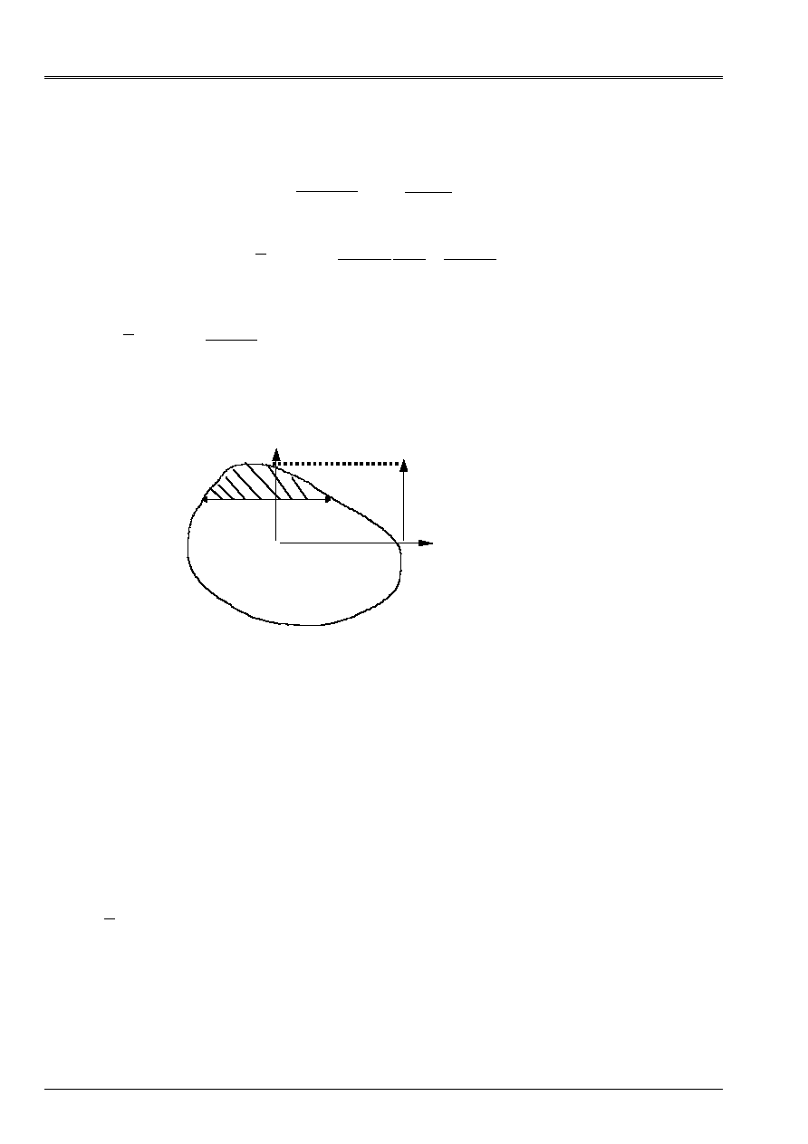
in accordance with [U4.24.01], with the notations of [Figure 2.1.1-b]. Quantity
()
m y
represent it
static moment on behalf of section (hatched) included/understood enters
y
and
y
max
:
G
B (y)
y
Z
y
max
()
m y
y Dy dz
S
y
$
$
=
Appear 2.1.1-b: section of beam
This distribution checks the boundary conditions well following three-dimensional problem there:
shearing is quite null on bottom fibers and higher (
y
y
=
min
, or
y
y
=
max
). But it
account holds that average of shearings according to Z.
By applying this formula to a full rectangular section, one finds a distribution parabolic
according to Y. By applying it to a beam of circular section, one finds a distribution parabolic in y
and in Z, which varies more slowly according to Z than according to Y.
This remains valid for the other full sections. For sections comprising of the holes, it is necessary
to take guard to consider only the matter in the calculation of
B y
()
.
2.1.2 Method of TIMOSHENKO
With the origin, TIMOSHENKO (ref. [bib9]) proposed a simple definition of the coefficient of shearing,
as being the relationship between the transverse shear stress average in the noted section
CT
and its maximum value
(
)
CT max
.
Owing to the fact that we always have the shearing action by:
V
dS
S
CT
=
éq
2.1.2-1
Code_Aster
®
Version
7.4
Titrate:
Calculation of the characteristics of a beam of cross section unspecified
Date:
01/09/05
Author (S):
J.M. PROIX, NR. LAURENT, P. HEMON, G. BERTRAND
Key:
R3.08.03-C
Page
:
11/42
Manual of Reference
R3.08 booklet: Machine elements with average fiber
HT-66/05/002/A
we deduce:
CT
V
S
=
.
Knowing that TIMOSHENKO proposes to write:
K
CT
CT
Max
=
éq
2.1.2-2
to determine
K
, it is enough to express the sharp effort
V
dS
S
CT
=
[éq 2.1.2-1] according to
CT
Max
. In the general case of the unspecified sections, there will be naturally two coefficients
K
y
and
K
Z
, for each of the two main axes.
It remains to determine
CT
Max
. For that, TIMOSHENKO makes an assumption on the distribution of
stresses shear transverse: the transverse shear stress has a distribution
parabolic in the direction of the shearing action which produces it, with its maximum value in the center and
zero values at the edges. This is true according to the formula of JOURAWSKI for a section
rectangular. By extension, the method extends this assumption of parabolic distribution to one
unspecified section
This method is not applied in Code_Aster, except for the hollow rectangular sections.
One uses the following method in the other cases.
2.1.3 Method
“energy”
Actually, the definition suggested by TIMOSHENKO proves little used in practice today; one him
prefer a formulation based on internal energy due to shearing in the section. The aforementioned is written:
U
G
dS
CT
S
CT
=
1
2
2
where
G
is the modulus of rigidity (equal to
µ
).
The new definition of the coefficient of shearing is sometimes allotted to MINDLIN and is expressed by:
U
V
K SG
CT
=
1
2
2
éq
2.1.3-1
So by substitution, one thus defines for a homogeneous material section the coefficient of
shearing by:
[
]
K
dS
S
dS
V
S
dS
CT
S
CT
S
CT
S
=
=
2
2
2
2
éq
2.1.3-2
Code_Aster
®
Version
7.4
Titrate:
Calculation of the characteristics of a beam of cross section unspecified
Date:
01/09/05
Author (S):
J.M. PROIX, NR. LAURENT, P. HEMON, G. BERTRAND
Key:
R3.08.03-C
Page
:
12/42
Manual of Reference
R3.08 booklet: Machine elements with average fiber
HT-66/05/002/A
By making an assumption on the distribution of stress in the section, one can thus estimate
value of
K
. From the formula of JOURAWSKI [éq 2.1.1-1], the preceding expression can be written
(ref. [bib5]):
K
I
S
m
y
B
y dS
S
=
()
()
2
2
2
éq
2.1.3-3
2.1.4 Method of COWPER
One can also take into account the three-dimensional effects to determine the coefficient
K
;
various formulations were proposed, by COWPER [bib3] and were taken again in particular by BLEVINS
[bib2], while being based on the resolution of the three-dimensional problem of Saint-Coming.
In this case, the coefficient
K
is a function of the Poisson's ratio, in general one
approximation with the first command. COWPER uses the three-dimensional equations of elasticity in
the dynamic case to propose an expression of
K
giving good results in statics and in
low frequency dynamics. The approximation which makes it possible to lead to the formula suggested consists with
to consider a distribution of not parabolic stress, but resulting from the static problem
(solved analytically) of the beam cantilever transversely charged at its loose lead. It is with
to note that the distribution obtained is strictly identical to the problem with a transverse loading
uniformly distributed.
2.2
Particular case of the sections rectangular and circular
One distinguishes the full beams and the tubes.
For the full rectangular section, the coefficient of shearing is determined by the method based
on energy shearing with parabolic distribution of the stresses interns
K
I
S
m
y
B
y
Dy
y
Z
S
Z
Z
=
()
()
2
2
2
[éq 2.1.3-3]. Applied to the rectangular section, one obtains
K
K
y
Z
= = 56
. It should be noted that this value also corresponds to the method of COWPER when
the Poisson's ratio is taken equal to zero.
For the rectangular tube, Code_Aster uses the method of TIMOSHENKO which leads to
K
K
y
Z
= = 23
.
In the case of the beams with full circular section, one uses the energy method which leads to
K
K
y
Z
= = 9
10
. This value is also obtained by the method of COWPER when it
Poisson's ratio is equal to
1
2
.
Code_Aster
®
Version
7.4
Titrate:
Calculation of the characteristics of a beam of cross section unspecified
Date:
01/09/05
Author (S):
J.M. PROIX, NR. LAURENT, P. HEMON, G. BERTRAND
Key:
R3.08.03-C
Page
:
13/42
Manual of Reference
R3.08 booklet: Machine elements with average fiber
HT-66/05/002/A
For the circular tubes, one distinguishes the tubes with fine wall and those with thick wall. If one notes
m
R
R
I
E
=
the report/ratio of the internal radius to the external radius, a tube is with fine wall when m
0.9, if not
it is with thick wall.
The coefficient of shearing of the circular tube with fine wall is given by the method of COWPER, in
considering that m = 1 and for a null Poisson's ratio, is
K
K
y
Z
= = 12
.
For the circular tubes with thick wall, one uses an approximate formula of the method of
COWPER which is written:
K
m
m
m
=
+,
+,
,
1
1 093
0 634
1156
0 905
2
3
,
-
.
Let us notice that this formula does not ensure continuity with the borderline cases of the full cylinder (m = 0)
and of the cylinder with infinitely thin wall (m = 1).
If preceding choices (carried out by
AFFE_CARA_ELEM
in the case of circular sections and
rectangular) are not appropriate, it is always possible to calculate the coefficients numerically
of shearing using
MACR_CARA_POUTRE
, the method is specified in the § according to.
2.3 Numerical method of calculation of the coefficients of shearing and of
center shearing
2.3.1 Calculation of the coefficients of shearing:
This method takes as a starting point the the ref. [bib1], page 62. It allows the simultaneous determination of
constants of shearing and the center of torsion. It is implemented in
MACR_CARA_POUTRE
,
starting from a plane mesh of the section. It functions currently only for sections
homogeneous and isotropic (for nonhomogeneous sections, the method is similar [bib1] but not
available in Code_Aster).
As for the energy method, one compares for a sharp effort
V
Z
internal energy
U
1
had with shearing in the section with energy U
2
associated the model of MINDLIN:
U
G
dS U
V
K SG
S
xy
xz
Z
Z
1
2
2
2
2
1
2
1
2
=
+
=
=
The coefficient of shearing is expressed by:
K
V
SGU
Z
Z
= 12
2
1
Code_Aster
®
Version
7.4
Titrate:
Calculation of the characteristics of a beam of cross section unspecified
Date:
01/09/05
Author (S):
J.M. PROIX, NR. LAURENT, P. HEMON, G. BERTRAND
Key:
R3.08.03-C
Page
:
14/42
Manual of Reference
R3.08 booklet: Machine elements with average fiber
HT-66/05/002/A
U thus should be calculated
1
and thus shear stresses (in elasticity) in the section for
to estimate the value of K .On is placed in the main reference mark of inertia (G, y, Z), and one supposes that
beam is subjected only to one sharp effort
V
Z
. It results from it that:
()
xx
y
y
xx
Z
y
Z M X
I
X
Z VI
=
=
The equilibrium equations make it possible to write:
xx
xy
xz
xy
xz
Z
y
X
y
Z
y
Z
Z VI
+
+
= =
+
+
0
In addition, the kinematics of the beam in bending/shearing is:
(
)
()
()
()
(
)
(
)
()
U X y Z
U X
Z
X
U y Z
v X y Z
W X y Z
W X
y
,
~,
,
,
=
+
+
=
=
0
()
~,
U y Z
representing axial displacement due to the roll of the section. Deformations
are written:
()
()
()
()
()
()
xx
y
xy
xz
y
U X
X
Z
X
X
U y Z
y
X
U y Z
Z
W X
X
=
+
=
=
+
+
2
2
~,
~,
By using the relation of behavior of linear elasticity, the stresses are written:
()
()
()
()
µ
µ
µ
µ
xy
xy
xz
xz
y
U y Z
y
X
U y Z
Z
W X
X
=
=
=
=
+
+
2
2
~,
~,
The components of shearing thus check:
xy
xz
Z
y
-
=
0
Code_Aster
®
Version
7.4
Titrate:
Calculation of the characteristics of a beam of cross section unspecified
Date:
01/09/05
Author (S):
J.M. PROIX, NR. LAURENT, P. HEMON, G. BERTRAND
Key:
R3.08.03-C
Page
:
15/42
Manual of Reference
R3.08 booklet: Machine elements with average fiber
HT-66/05/002/A
This relation makes it possible to introduce the function of stresses
Z
such as shear stresses
in the section are written:
µ
µ
xy
Z
xz
Z
y
Z
=
=
The equilibrium equation then makes it possible to obtain the function
Z
by resolution of a problem
quasi-harmonic which is written:
G
F
S
G N
S
Z
Z
Z
+ =
=
=
0
0
0
in
with
on
in a point
=
F
zV
I
Z
y
This makes it possible to calculate
Z
then shearings. In practice, in
MACR_CARA_POUTRE
, one uses
THER_LINEAIRE
to solve the problem, while assimilating
Z
at the temperature. One chooses
V
Z
=1 and
G=1 (G does not intervene any more in the expression of the coefficient of shearing). Boundary conditions of
this problem of stationary thermics are:
·
source F being worth
zV
I
Z
y
·
null flow on
S
·
null temperature in a point of
S
One can then determine
()
U
G
dS
G
Z
S
xy
xz
S
1
1
2
1
2
2
2
2
=
Z
+
=
by a calculation
elementary on all the elements of the section, with the option
“CARA_CISA”
(calculation of the gradient), then
summation on these elements. One calculates then
K
V
Z
Z
= 12
2
SGU
1z
Same calculation is carried out with
V
y
=
1
to determine
K
V
y
y
y
= 12
2
1
SGU
The provided result is
With
K
With
K
y
y
Z
Z
=
=
1
1
,
.
2.3.2 Calculation of the co-ordinates of the center of shearing
The center of shearing C is the point of the section where shear stresses due to an effort
edge generate one null torque. This point is also called center of torsion, because it
remain fixed when the section is only subjected to one torque.
The torque compared to the point G is worth:
(
)
M
y
Z dS
xz
xy
S
xG
=
.
.
-
Code_Aster
®
Version
7.4
Titrate:
Calculation of the characteristics of a beam of cross section unspecified
Date:
01/09/05
Author (S):
J.M. PROIX, NR. LAURENT, P. HEMON, G. BERTRAND
Key:
R3.08.03-C
Page
:
16/42
Manual of Reference
R3.08 booklet: Machine elements with average fiber
HT-66/05/002/A
The torque compared to the point C sought is:
(
)
(
)
(
)
M
y y
Z Z dS
M
V
Z V
xz
C
xy
C
S
Z
C y
teststemxç
xG
C
=
y
.
-
-
-
=
-
+
To determine the co-ordinates of the center of shearing, preceding calculation is used [bib1]:
From the shear stresses determined for
V
Z
=1 and
V
y
=0, one calculates
:
(
)
M
y
Z dS
Z
xz
xy
S
xG
=
.
.
-
One obtains:
y
=
C
xG
xG
=
M
V
M
Z
Z
Z
For
V
y
=1 and
V
Z
=0, one obtains:
Z
= -
C
xG
xG
= -
M
V
M
y
y
y
2.3.3 Example
Let us take again the example of the rectangular section [§1.1.4].
B
B
y
GR2
GR1
H
H
X
0
B = 0.01
H = 0.025
The coefficients of shearing obtained are identical to the analytical value (6/5).
PLACE AY AZ EY
EZ
all 1.20E+00 1.20E+00 8.72E-19 3.16E18
Co-ordinates of the center of torsion EY and EZ (in the reference mark main (G, y, Z)) are null:
center shearing/torsion is actually confused with the center of gravity.
2.4
Calculation of the coefficients of shearing of a network
The method described in appendix 2 makes it possible to calculate coefficients of shearing of a beam
equivalent to a whole of parallel beams embedded on a rigid floor and embedded or
rotulées on another.
Code_Aster
®
Version
7.4
Titrate:
Calculation of the characteristics of a beam of cross section unspecified
Date:
01/09/05
Author (S):
J.M. PROIX, NR. LAURENT, P. HEMON, G. BERTRAND
Key:
R3.08.03-C
Page
:
17/42
Manual of Reference
R3.08 booklet: Machine elements with average fiber
HT-66/05/002/A
3
Constants related to torsion
The constant of noted torsion
C
must allow to take account of the roll of the sections
straight lines (not circulars) at the time of a deformation in torsion. It is used in the models of beams
straight lines treated by Aster (EULER, TIMOSHENKO and warped TIMOSHENKO or
POU_D_E
,
POU_D_T
,
POU_C_T
and
POU_D_TG
). In the case of the circular sections, the sections are not warped and
constant of torsion is equal to the polar geometrical moment
I
p
. The constant of torsion C is
defined as the moment necessary to produce a rotation of 1
radian per unit of length
divided by the modulus of rigidity, that is to say:
C
M
X
X
X
=
µ
éq 3-1
C
with the same dimension as the geometrical moments of inertia
I
I
y
Z
and
that is to say
M
4
.
For a circular section, the definition [éq 3-1] is coherent since we have:
M
I
X
X
p
X
=
µ
.
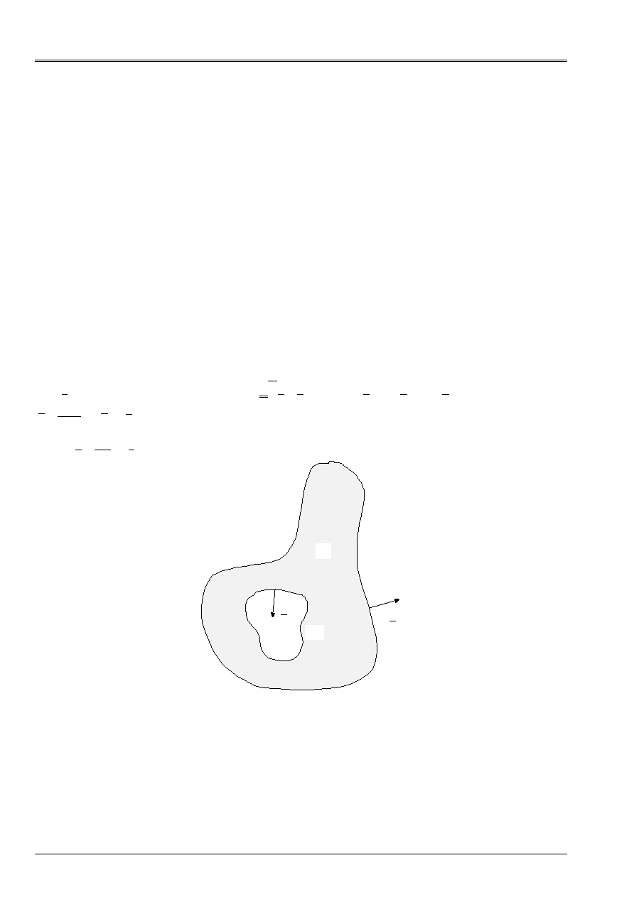
Determination of
C
in the general case is made in a numerical way (
MACR_CARA_POUTRE
) and
tiny room to a calculation of Laplacian in 2D. The method presented here is detailed in the ref. [bib1] [§3.6.3]
for the simply related sections. An original method for calculation of the constants of
torsion with perforated sections is detailed in appendix. The results here are given.
3.1
Calculation of C in the case of unspecified sections
The complete resolution of the problem is in appendix. One gives here simply the results.
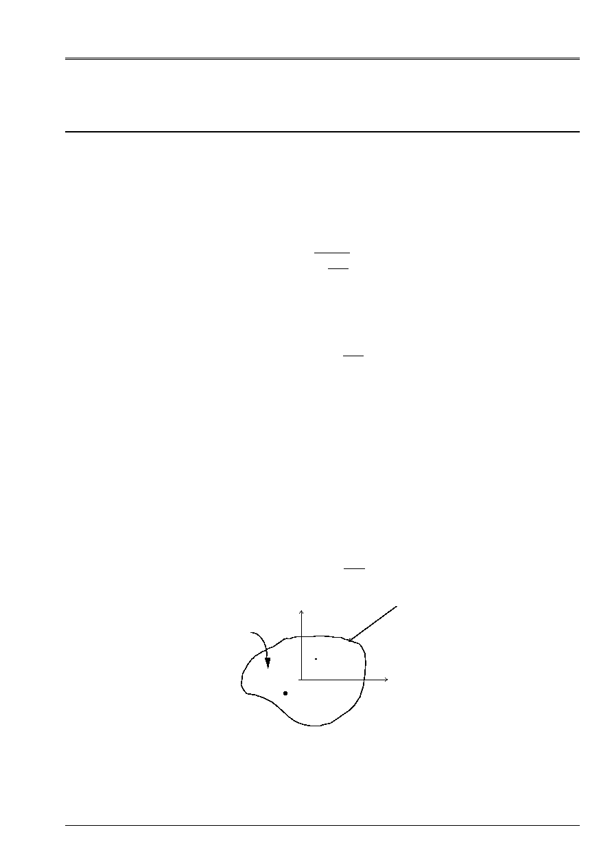
According to the assumptions of the theory of the pure torsion of Saint-Coming, there is no deformation of
the average line and not of lengthening along the longitudinal axis. Torsion is free, i.e.
that it does not generate axial stresses. In other words, the sections can warp
freely. If one remains in small displacements, one admits that the swing angle of the cross-sections
is worth:
()
X
X
X X
X
X =
=
.
éq
3.1-1
(S)
(
)
y
Z
C
G
M (y, Z)
Appear 3.1-a
Code_Aster
®
Version
7.4
Titrate:
Calculation of the characteristics of a beam of cross section unspecified
Date:
01/09/05
Author (S):
J.M. PROIX, NR. LAURENT, P. HEMON, G. BERTRAND
Key:
R3.08.03-C
Page
:
18/42
Manual of Reference
R3.08 booklet: Machine elements with average fiber
HT-66/05/002/A
If the point C is the center of torsion (which by definition remains motionless when the beam is subjected to
a torsion), the field of displacement
()
U M
is given by [bib1]:
()
(
)
(
)
()
U
=
=
+
,
M
U
v
W
X X
X
y y
Z Z
X
y Z
X
C
C
X
-
-
0
0
0
0
()
(
)
(
)
=
,
X
X
C
X
C
X
y Z
X X Z Z
X X there y
-
-
-
where
()
,
y Z
is related to roll.
The law of HOOKE is written:
(
)
()
I
+
Trace
2
2
µ
µ
-
=
E
where
I
is the matrix unit and the tensor of the deformations is worth
(
)
=
() +
()
1
2 grad
grad
T
U
U
By neglecting the terms of the second command, in
2 X
X
2
, one leads to:
=
+
+
µ
X
X
y
Z
Z
y
y
Z
Z
y
0
0
0
0
0
-
-
=
µ
X
X
Z
y
Z
y
0
0
0
0
0
-
-
éq
3.1-2
One posed:
()
,
y Z
function of stress. It is noted that the relation of balance
div
=
0
is then
checked.
While deriving, one obtains:
2
2
2
2
2
2
1
1
y
Z y
Z
y Z
=
=
.
-
-
-
By adding the two equations, one leads to:
= -
2
éq 3.1-3
Code_Aster
®
Version
7.4
Titrate:
Calculation of the characteristics of a beam of cross section unspecified
Date:
01/09/05
Author (S):
J.M. PROIX, NR. LAURENT, P. HEMON, G. BERTRAND
Key:
R3.08.03-C
Page
:
19/42
Manual of Reference
R3.08 booklet: Machine elements with average fiber
HT-66/05/002/A
It remains to establish the boundary conditions. One notes
N
the normal directed towards outside at the border
(
) which can be multiplement related:
I
N
N
0
Without external loading, one must have
=
N 0
, which can be written
:
=
µ
X
y
Z
X
Z N
y N
-
0
0
0
where
N
y
and
N
Z
are the two components of the normal.
This writing can be thus put in the form
N
=
grad
0
who implies that the vectors
N
and
grad
are colinéaires. It thus follows that
()
y Z
,
is constant on each related component
border (
). One can impose for example that
()
y Z
,
that is to say null on external contour:
=
0
on
0
=
=
I
on
I
If the sections behavior of the holes, constants
I
are unspecified. For
to allow the resolution of the complete problem, it is necessary to add equations. Those are obtained with
to leave the circulation of the function of roll on each closed contour. They are obtained
following conditions:
()
N DLL
I
I
=
2
Code_Aster
®
Version
7.4
Titrate:
Calculation of the characteristics of a beam of cross section unspecified
Date:
01/09/05
Author (S):
J.M. PROIX, NR. LAURENT, P. HEMON, G. BERTRAND
Key:
R3.08.03-C
Page
:
20/42
Manual of Reference
R3.08 booklet: Machine elements with average fiber
HT-66/05/002/A
where
()
I
is the surface surrounded by the border
()
I
. These conditions are brought back to conditions
conventional of imposed flow (where
()
L
I
represent the length of the border
I
):
()
()
N
L
I
I
=
2
Finally, the problem to be solved is written:
= -
2
on
=
0
on
0
=
=
I
on
I
()
()
N
L
I
I
=
2
Once solved this problem, one obtains the constant of torsion by:
()
C
ds
I
I
N
I
=
+
=
-
2
2
1
1
.
3.2
Calculation of the constant of torsion in
MACR_CARA_POUTRE
This calculation is carried out in
MACR_CARA_POUTRE
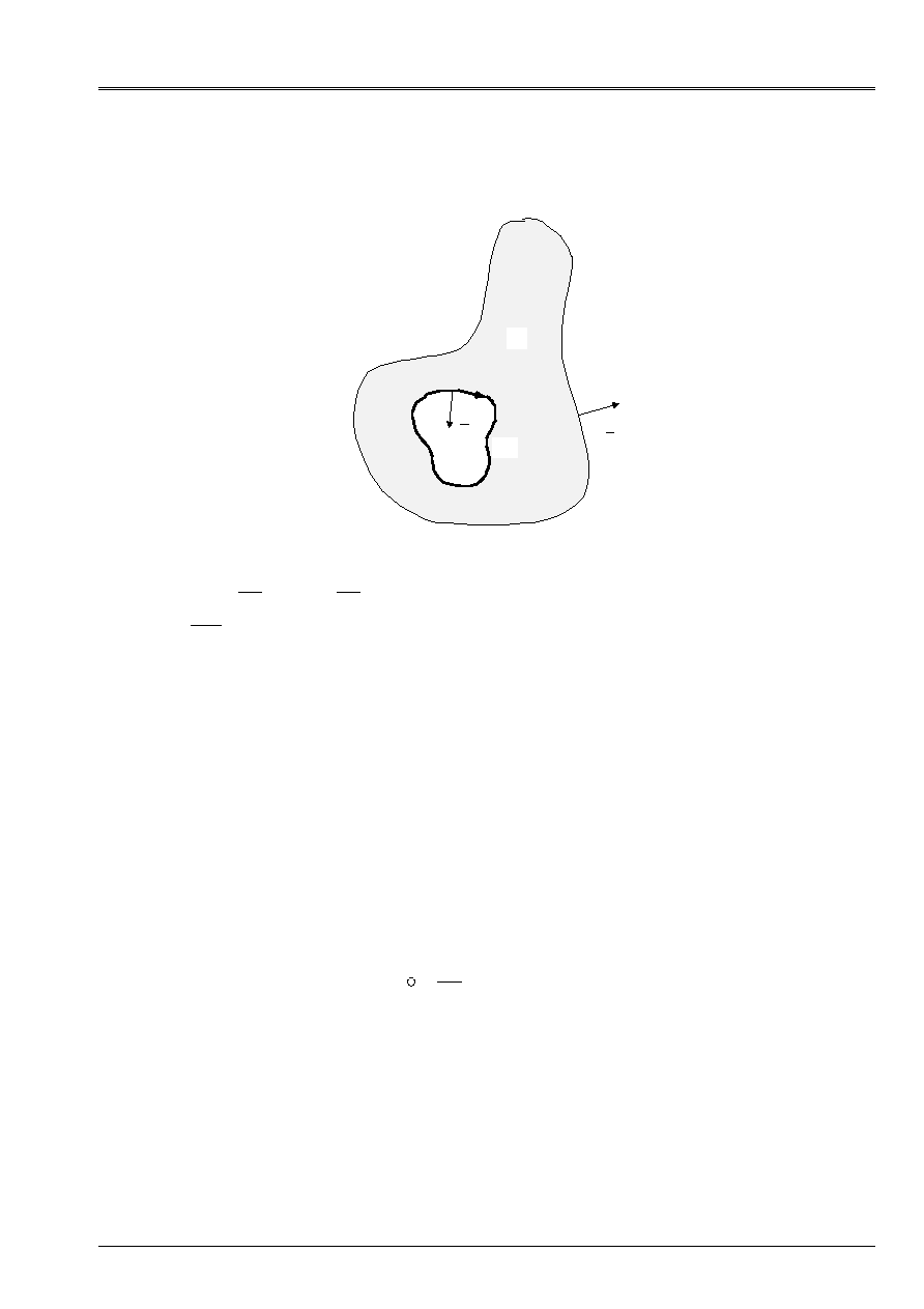
by the resolution of a problem of thermics. It is necessary
for that that the user specifies with
MACR_CARA_POUTRE
the group of mesh which defines the edge
outside, and if the section comprises holes, groups of meshs which define the contour of
each one of them.
One solves a linear problem of thermics then (
THER_LINEAIRE
) on a plane mesh of
section to find the function
. One places oneself first of all in the main reference mark of inertia
(
CREA_MAILLAGE
), starting from the co-ordinates of the center of gravity and the orientation of the main reference mark
calculated previously.
One defines then the boundary conditions in
AFFE_CHAR_THER
:
·
The source term is worth 2
·
The temperature of the external edge is imposed and is worth 0 (
TEMP_IMPO
)
·
And if the section comprises holes (presence of one or more groups of meshs them
defining):
- On each group of mesh defining a hole, the temperature is constant
(
TEMP_UNIF
)
-
Flow is worth 2 times the surface of the hole divided by the length of its edge. These quantities are
calculated before.
·
The calculation of C is carried out in
POST_ELEM
by the key word
CARA_TORSION
key word factor
CARA_POUTRE
. In this case, one calculates on each element the integral of
, (option
CARA_TORSION
on the plane thermal elements), then one carries out the sum on all them
elements.
Code_Aster
®
Version
7.4
Titrate:
Calculation of the characteristics of a beam of cross section unspecified
Date:
01/09/05
Author (S):
J.M. PROIX, NR. LAURENT, P. HEMON, G. BERTRAND
Key:
R3.08.03-C
Page
:
21/42
Manual of Reference
R3.08 booklet: Machine elements with average fiber
HT-66/05/002/A
Example:
Still let us take again the example of the rectangular section [§1.1.4].
The coefficients of shearing obtained are:
PLACE
CT [éq 3.3.2] CT (Aster)
all 9.9805E-08
9.9681E-08
3.3
Calculation of the radius of torsion in an unspecified section
The radius of torsion is calculated thanks to the calculation of the function of stresses on the mesh of
section. Rt is added in the table produced by
MACR_CARA_POUTRE
[U4.42.02].
The resolution of a stationary thermal problem of unknown factor
allows to determine the constant
of torsion and stresses shear.
The determination of the radius of Rt torsion is the resolution of:
Rt = grad (
) .n
(or N represents the normal vector external with the edge considered of the section)
Rt varies along external contour; indeed, for an unspecified section, shearings due to
torsion vary on the edge. One chooses to take the value of Rt leading to shearings
maximum on the external edge, i.e. the maximum value of Rt (in absolute value) on contour
external.
Moreover, if the section is alveolate, there are several “several radii of torsion”: Rt = 2 * A (K)/L (K) (or
With (K) represents the surface of the cell K and L (K) its perimeter). If one is satisfied to seek the value
maximum of shearing, it is necessary to take the maximum of the Rt values obtained on the external edge and
on the cells.
The radius of torsion is given in
MACR_CARA_POUTRE
only by controls
python. During the unfolding of
MACR_CARA_POUTRE
the control
POST_ELEM
is called, one
new parameter RT is thus created for this control.
3.4
Constant of torsion of the sections circular and rectangular
Expressions simplified for these two types of sections are described here. The calculation of
constants of torsion is then directly carried out in
AFFE_CARA_ELEM
.
For the circular section the preceding expressions remain valid. By taking a function of
torsion of the form
()
(
)
,
=
y Z
R
X
y
1
2
2
2
2
-
-
one finds indeed:
(
)
C
I
R
R
p
=
=
-
2
04
14
For the rectangular section, calculation is naturally more complex but can be carried out in
choosing a function which is cancelled indeed at the edges, of the form:
()
(
)
(
)
, =
+
+
y Z
With
I
y
H
J
Z
H
I
J
ij
y
Z
=
=
0
0
2 1
2
1
cos
cos
.
Code_Aster
®
Version
7.4
Titrate:
Calculation of the characteristics of a beam of cross section unspecified
Date:
01/09/05
Author (S):
J.M. PROIX, NR. LAURENT, P. HEMON, G. BERTRAND
Key:
R3.08.03-C
Page
:
22/42
Manual of Reference
R3.08 booklet: Machine elements with average fiber
HT-66/05/002/A
The resolution involves with a constant of torsion which is written:
C
H
H
H
H
C hh
H H
C
H
H
H
H
y
Z
y
Z
y
Z
y
Z
y
Z
Z
y
=
+
=
+
3
3
2
2
3
2
1
éq
3.4-1
where
C hh
y
Z
express yourself in the form of a series which takes the following values:
H
H
C hh
y
Z
y
Z
1
2
4
8
0.281 0.286 0.299 0.312 1 3
,
,
,
,
/
In fact, Code_Aster employs a formula simplified (ref. [bib1]) for the full rectangular section
who is written:
C
H H
H
H
H
H
y
Z
Z
y
Z
y
=
,
+,
3
5
16
16
3
3 36
0 280
-
éq
3.4-2
It is valid if
H
H
y
Z
>
; in the other case it is enough to exchange the respective places of
H
H
y
Z
and
.
agreement between the two expressions is very good as indicates it the following table:
H
H
y
Z
1 2 4 8
C
H H
y
Z
3
according to [éq 3.3-1]
0,1405
0,2288
0,2814
0,3072
1/3
C
H H
y
Z
3
according to Aster [éq 3.3-2]
0,1408
0,2289
0,2809
0,3071
1/3
For the hollow rectangular beam, there is an approximate solution which is written (ref. [bib2] and [bib6]):
(
)
(
)
C
ep ep H
ep
H
ep
H ep
ep
H ep
ep
y
Z
y
y
Z
Z
y
y
y
Z
Z
Z
=
+
2
2
2
2
2
-
-
-
-
with the notations of [Figure 1.2-a]: section in plan (0, y, Z).
Code_Aster
®
Version
7.4
Titrate:
Calculation of the characteristics of a beam of cross section unspecified
Date:
01/09/05
Author (S):
J.M. PROIX, NR. LAURENT, P. HEMON, G. BERTRAND
Key:
R3.08.03-C
Page
:
23/42
Manual of Reference
R3.08 booklet: Machine elements with average fiber
HT-66/05/002/A
3.5
The effective radius of torsion
The effective radius of torsion
R
T
allows to calculate the transverse shear stress of torsion
maximum
T
M
according to the torque. One will be able to consult on this subject the drafting of
MASSONET on this aspect (ref. [bib5]). We have as follows:
T
X
T
M
MR. RC
=
In the case of circular cylinders,
R
T
is equal to the radius (external if it is a tube) of the section.
For the rectangular sections, the problem is definitely more complex. Code_Aster imposes it
radius of torsion of the full section by:
(
)
R
C
H
H
H
H
T
y
Z
y
Z
=
+,
+
4 3
18
2
2
This approximate expression remains valid if the beam is not flattened too much. DHATT and BATOZ
(ref. [bib1]) give an expression having a field of validity more extended, but actually it acts
in any rigor of a series whose numerical values are given by MASSONET (ref. [bib5]).
For the hollow rectangular beam, Code_Aster imposes an expression which is valid only if
wall is thin and constant thickness
ep
Z
, that is to say:
(
)
(
)
R
C
ep H
ep
H
ep
T
Z
y
y
Z
Z
=
-
-
2
2
It is about a “adaptation” of the formula:
R
C
E With
T
=
2
where
E
is the thickness of the wall (constant) and
With
the surface contained inside the average line.
This last expression is known under the name of first formula of BREDT (cf ref. [bib1] and
[bib5]).
Code_Aster
®
Version
7.4
Titrate:
Calculation of the characteristics of a beam of cross section unspecified
Date:
01/09/05
Author (S):
J.M. PROIX, NR. LAURENT, P. HEMON, G. BERTRAND
Key:
R3.08.03-C
Page
:
24/42
Manual of Reference
R3.08 booklet: Machine elements with average fiber
HT-66/05/002/A
4
Calculation of the constant of roll
The constant of roll is used by the model of beam with roll
(modeling
POU_D_TG
and
POU_D_TGM
), that it is important to take into account for the beams with
open mean sections (cf [R3.08.04]).
This coefficient (noted
I
in [R3.08.04]) intervenes in the expression of the virtual work of the efforts
interiors on the terms of torsion:
(
)
W
C
E I
dx
X X
X X
X xx
X xx
int
,
*
,
,
*
,
.
.
.
=
+
µ
0
2
I
express yourself in the same unit as the geometrical moments of inertia
I
I
y
Z
,
,
that is to say
M
4
.
By taking again the approach of [§3.1], and while placing itself in a reference mark related to the center of torsion C,
kinematics of the torsion of an unspecified section is:
()
()
U
=
=
+
,
M
U
v
W
X X
X
y
Z
X
y Z
X
X
0
0
0
0
()
=
,
X
X
X
X
y Z
X X Z
X X y
-
where
()
,
y Z
is related to roll (which cancels only in the case of a section
circular).
The expression of the stress field is (in elasticity):
()
()
()
µ
µ
µ
µ
xx
xx
X
xy
xy
X
xz
xz
X
E
E y Z
X
X
y Z
y
Z
X
y Z
Z
y
=
=
=
=
-
=
=
-
,
,
,
2
2
2
2
With the difference of [§4], terms of the second command in
2
2
X
X
are not neglected any more.
The first relation of balance
(
)
div
,
,
,
X
xx X
xy y
xz Z
=
+
+
=
0
imply the condition then
following on the function of roll:
=
0
In addition, without loading external on contour of the section, one must have
=
N 0
, which
can be written:
+
y N
Z N
Z N
y N
y
Z
y
Z
=
-
.
.
, where
N
y
and
N
Z
are the two components of
normal, or in vectorial form:
(
)
grad N
N
N CM .x
.
=
=
Code_Aster
®
Version
7.4
Titrate:
Calculation of the characteristics of a beam of cross section unspecified
Date:
01/09/05
Author (S):
J.M. PROIX, NR. LAURENT, P. HEMON, G. BERTRAND
Key:
R3.08.03-C
Page
:
25/42
Manual of Reference
R3.08 booklet: Machine elements with average fiber
HT-66/05/002/A
This determines the function of roll except for a constant. To raise this indetermination,
one writes for example the expression of the normal effort (for a section where torsion produces
roll):
NR
ds
E
X ds
xx
S
S
X
=
=
=
2
2
0
thus the additional condition on the function of roll is:
S
ds
=
0
In practice, in
MACR_CARA_POUTRE
, one places oneself above all in a reference mark related to the center of torsion
C.
One calculates then
who must check:
(
)
= 0
grad N
N
N CM .x
.
=
=
=
ds
S
0
The inertia of roll
I
is obtained then by:
I
ds
S
=
2
MACR_CARA_POUTRE
fact call to the following elementary controls:
·
Translation of the co-ordinates of the nodes in the reference mark related to the center of torsion (calculated
previously in table TCARS):
CREA_MAILLAGE (MESH:
IDENTIFY: (TABLE:TCARS NOM_ORIG: “TORSION”));
·
Assignment of a model (thermal plan), of a material field:
AFFE_MODELE (MESH:
AFFE: (ALL: “YES” PHENOMENON: “THERMAL” MODELING:“PLANE”));
AFFE_MATERIAU (MESH
AFFE: (ALL: “YES” MATER: ));
·
Boundary conditions on external contour G0:
+
y N
Z N
Z N
y N
y
Z
y
Z
=
-
.
.
F1=DEFI_FONCTION (NOM_PARA: VALE: (0., 0., 10., - 10. )) ;
F2=DEFI_FONCTION (NOM_PARA: VALE: (0., 0., 10., 10. )) ;
CH1 = AFFE_CHAR_THER_F (MODEL:
FLUX_REP: (GROUP_MA: G0 FLUX_X: F1 FLUX_Y: F2)) ;

Code_Aster
®
Version
7.4
Titrate:
Calculation of the characteristics of a beam of cross section unspecified
Date:
01/09/05
Author (S):
J.M. PROIX, NR. LAURENT, P. HEMON, G. BERTRAND
Key:
R3.08.03-C
Page
:
26/42
Manual of Reference
R3.08 booklet: Machine elements with average fiber
HT-66/05/002/A
·
Condition on the field solution:
S
ds
=
0
: creation of a unit source term on all it
mesh, and of the vector second associate member.
LIAISON_CHAMNO
then allows to impose
desired condition.
CHS = AFFE_CHAR_THER (MODEL:
SOURCE: (ALL: “YES” SOUR: 1.));
VS = CALC_VECT_ELEM (OPTION: “CHAR_THER” CHARGES: CHS…);
MS = CALC_MATR_ELEM (MODEL: … OPTION: “RIGI_THER”);
NUM = NUME_DDL (MATR_RIGI: Ms);
= ASSE_VECTEUR (VECT_ELEM GOES: VS NUME_DDL: NUM);
CH2 = AFFE_CHAR_THER (
LIAISON_CHAMNO: (CHAM_NO: COEF_IMPO GOES: 0.));
·
Calculation of the function of roll
THER_LINEAIRE (MODEL: ….
EXCIT: (LOAD: CH1)
EXCIT: (LOAD: CH2)
);
·
Calculation of the constant of roll
I
ds
S
=
2
and enrichment of the table:
TCARS = POST_ELEM (MODEL:…
CARA_POUTRE: (CARA_GEOM: TCARS
LAPL_PHI:KSI OPTION:“CARA_GAUCHI”));

Code_Aster
®
Version
7.4
Titrate:
Calculation of the characteristics of a beam of cross section unspecified
Date:
01/09/05
Author (S):
J.M. PROIX, NR. LAURENT, P. HEMON, G. BERTRAND
Key:
R3.08.03-C
Page
:
27/42
Manual of Reference
R3.08 booklet: Machine elements with average fiber
HT-66/05/002/A
5 Bibliography
[1]
BATOZ J.L. & DHATT G.: “Modeling of the structures by finite elements. Volume 2, beams
and plates ". HERMES, Paris, 1990
[2]
BLEVINS R.D.: “Formulated for natural frequency and shape mode”. Van Nostrand Reinhold,
New York, 1979.
[3]
COWPER G.R.: “The shear coefficient in Timoshenko' S beam theory”. J. off Applied
Mechanics, June 1966, p 335-340.
[4]
HSU Y.W.: “The shear coefficient off beams off circular cross-country race section”. J. off Applied
Mechanics, March 1975, p 226-228.
[5]
MASSONET C. & CESCOTTO S.: “Mechanical of materials”. Of boeck University,
Brussels, 1994.
[6]
PILKEY W.D.: “Formulated for stress, Strain and Structural Matrices”. Wiley & Sounds, New York,
1994.
[7]
REISSNER E. & TSAI W.T. : “One the determination off the centers off twist and off shear for
cylindrical Shell beams ". J. off Applied Mechanics, december 1972, p 1098-1102.
[8]
BAMBERGER Y.: Run of Resistance of Materials - National School of Bridges and
Roadways. 1994.
[9]
TIMOSHENKO S. Résistance of Materials - Dunod 1968
[10]
Document [U4.24.01]: Operator
AFFE_CARA_ELEM
[11]
VOLDOIRE F: “Elements of resistance of materials. Directed work of the ENPC”. Note
EDF/MN HI-74/96/002/0
Code_Aster
®
Version
7.4
Titrate:
Calculation of the characteristics of a beam of cross section unspecified
Date:
01/09/05
Author (S):
J.M. PROIX, NR. LAURENT, P. HEMON, G. BERTRAND
Key:
R3.08.03-C
Page
:
28/42
Manual of Reference
R3.08 booklet: Machine elements with average fiber
HT-66/05/002/A
Appendix 1 Determination of the constant of torsion for
sections has borders multiplement related
That is to say a beam elastic, isotropic, length
L
and of unspecified section
who can be not simply
related. One notes
0
contour external of
and
I
, for
I
N
=
-
1
1
K
, possible contours
interiors. One notes
=
=
-
I
I
N
0
1
U
its total border.
The axis is chosen
X
1
according to the line of the centers of gravity of the cross-sections. One supposes to simplify
demonstration which the center of torsion is confused with the center of gravity, which makes it possible to uncouple them
effects of torsion and bending. Axes
X
2
and
X
3
the main directions of inertia are selected following.
0
I
X
3
X
1
X
2
G
0
G
1
Appear A1-a: Beam in unspecified section
The beam is charged on its section
X
L
1
=
by one torque
M
M X
G
T
1
1
=
.
In addition, the side surface of the cylinder is not charged and the forces of volume are null.
One immediately deduces from it that the torque from the interior forces at the point
G
0
is
M
M X
G
T
0
1
=
The problem of elasticity posed previously seems incompletely definite. Indeed, conditions
with the limits on the cross-sections
X
L
1
=
and
X
1
0
=
are incomplete because there is not a condition in each
not, but on average. There is thus, a priori, an infinity of solutions. The assumption of Saint-Coming consists with
to seek a solution such as the tensor of the stresses is form
=
11
12
13
12
13
0
0
0
0
The principle of Saint-Coming is valid far from the sections of application of the forces. Indeed, except in cases
particular loadings, the four presumedly null terms diminish exponentially with
X
1
.
To solve this problem of elasticity, a formulation in stresses is chosen. The equations to be written are
thus those of balance and those of compatibility.
Code_Aster
®
Version
7.4
Titrate:
Calculation of the characteristics of a beam of cross section unspecified
Date:
01/09/05
Author (S):
J.M. PROIX, NR. LAURENT, P. HEMON, G. BERTRAND
Key:
R3.08.03-C
Page
:
29/42
Manual of Reference
R3.08 booklet: Machine elements with average fiber
HT-66/05/002/A
Equilibrium equations
div
=
0
lead to the three following scalar equations:
1 11
2
12
3
13
0
+
+
=
éq A1-1
1 12
1 13
0
0
=
=
éq A1-2
(with the simplified notation:
I
jk
jk
I
X
=
)
The equations of Beltrami, which take account of the equations of compatibility are written:
-
-
=
11
11 11
0
éq A1-3
-
- +
=
12
12
11
1
1
0
éq A1-4
-
- +
=
13
13 11
1
1
0
éq A1-5
-
+
=
22
11
11
0
éq A1-6
-
=
23
11
0
éq A1-7
-
+
=
33 11
11
0
éq A1-8
The equations [éq A1-3], [éq A1-6] and [éq A1-8] show that
11 11
,
22
22
0
=
and
33 11
are solutions of one
homogeneous linear system and thus that
11 11
22
11
33 11
0
=
=
=
. With the equation [éq A1-7], one deduces some
that
(
) (
)
11
1 1
0
1 1
0
2
1 1
0
3
=
+
+
+
+
+
X has
has
B X
B X
C X
C X
. By taking account of the fact that one deals with the problem of
free torsion, one will take
11
no one from now.
The equations [éq A1-2] and [éq A1-5] show that
12
and
13
do not depend on
X
1
. The equation [éq A1-1]
is written:
()
[
]
()
[
]
2
12
3
3
13
2
+
=
-
-
F X
G X
where
F
and
G
are two arbitrary functions. According to the theorem of Schwartz, there exists
(
)
X X
2
3
,
such as:
()
()
()
()
2
13
2
3
12
3
12
3
3
13
2
2
= -
-
=
+
=
=
-
= -
+
F X
G X
F X
G X
The equations [éq A1-4] and [éq A1-5] give:
3
2
0
0
=
=
that is to say
=
-
+
3
2
F
F
K
Code_Aster
®
Version
7.4
Titrate:
Calculation of the characteristics of a beam of cross section unspecified
Date:
01/09/05
Author (S):
J.M. PROIX, NR. LAURENT, P. HEMON, G. BERTRAND
Key:
R3.08.03-C
Page
:
30/42
Manual of Reference
R3.08 booklet: Machine elements with average fiber
HT-66/05/002/A
where
K
is a constant of integration. Like
F
and
G
are arbitrary, one will take them identically null.
The problem to be solved is thus a problem of Laplacian:
=
K
on
then
=
-
-
0
0
0
0
0
3
2
3
2
It remains to write the boundary conditions, who will allow us to write conditions on
for
and on
K
The boundary conditions are to be written on all the border.
On the cross-sections
X
L
1
=
(and the same in
X
1
0
=
), one a:
12
0
ds
=
13
0
ds
=
X
X
ds
M
T
2 13
3 12
-
=
éq A1-9
That is to say
N
the normal external with
. One has
=
N 0
. One poses
=
+
12
2
13
3
X
X
. One can also write
=
grad
X
1
;
the tangential part of the stress in the cross-section is called. That is to say
NR
I
the point
running of contour
I
for
I
N
=
-
0
1
K
. The condition, on side surface, stated higher, can
to be written
=
dN
I
0
.
I
N
N
0
Appear A1-b: Definition of the normals
Code_Aster
®
Version
7.4
Titrate:
Calculation of the characteristics of a beam of cross section unspecified
Date:
01/09/05
Author (S):
J.M. PROIX, NR. LAURENT, P. HEMON, G. BERTRAND
Key:
R3.08.03-C
Page
:
31/42
Manual of Reference
R3.08 booklet: Machine elements with average fiber
HT-66/05/002/A
Thus, on the side surface of a beam, the vector forced tangential
is tangent with contour.
·
The equation
=
dN
I
0
conduit in a condition which must observe
on contour:
D
=
0
·
The equation [éq A1-9] led to
M
X
X
ds
T
=
-
-
2 2
3 3
that one can also write:
M
ds
X dx
X dx
T
=
+
-
2
3
2
2
3
(
)
The problem to solve to obtain
is thus:
=
K
on
D
=
0
on
with the stress
(
)
M
ds
X dx
X dx
T
=
+
-
2
3
2
2
3
It remains to identify the constant of torsion C.
The law of behavior of the beams in torsion is:
M
CG
X
T
X
=
(cf [§3]).
To solve the preceding problem more easily, one poses
=
C
X
X
and
K
C
X
X
= -
2
, the problem with
to solve becomes then:
= -
2
on
D
=
0
on
(
)
M
C
X
ds
X dx
X dx
T
X
= -
+
-
2
3
2
2
3
With such a notation, one obtains
(
)
C
ds
X dx
X dx
=
+
-
2
3
2
2
3
Contour
consists of several contours: an external contour
0
and
N
-
1
interior contours
I
. The condition
D
=
0
conduit with
N
following conditions:
=
I
on
I
for
I
N
=
-
0
1
K
.
I
are constant unknown factors. By noting that
, and thus
, is defined except for a constant, one can fix one
I
. One will thus take
0
0
=
. Remain to determine
I
for
I
N
=
-
1
1
K
.
For that, one will study the roll of the cross-section of X-coordinate
X
1
. Let us recall that the tensor of
stresses is written (cf [§4]):
=
+
+
G
X
y
Z
Z
y
y
Z
Z
y
X
0
0
0
0
0
-
-
=
G
X
Z
y
Z
y
X
0
0
0
0
0
-
-
Code_Aster
®
Version
7.4
Titrate:
Calculation of the characteristics of a beam of cross section unspecified
Date:
01/09/05
Author (S):
J.M. PROIX, NR. LAURENT, P. HEMON, G. BERTRAND
Key:
R3.08.03-C
Page
:
32/42
Manual of Reference
R3.08 booklet: Machine elements with average fiber
HT-66/05/002/A
One poses
=
grad
X
1
;
is (except for a constant) the tangential part of the vector forced in
cross-section.
One thus has:
grad
= -
GM X
1
One makes circulate this equation along
I
, one a:
0
3
2
2
3
=
-
-
DLL
X dx
X dx
I
I
One was useful oneself here owing to the fact that the circulation of the gradient on a closed curve is null.
It is noted that the first integral can be written in term of flow of
beam
I
. In addition, the second
integral is equal to
()
2
I
.
Finally, the problem is written:
= -
2
on
=
0
on
0
=
I
on
I
()
N DLL
I
I
=
2
Once solved this problem, one a:
()
J
ds
I
I
N
I
=
+
=
-
2
2
1
1
The last condition:
()
N DLL
I
I
=
2
is difficult to treat in a numerical way. Actually, both
conditions on each border bordering a hole are written:
=
I
on
I
()
()
N
L
I
I
I
=
2
on
Variational formulation:
()
=
v H
v
1
0
0
such as
()
µ
L
I
2
()
+
=
+
=
=
µ
µ
v D
v DLL
v D
v DLL
DLL
DLL
DLL
I
I
I
I
I
I
I
I
I
I
2
2
0
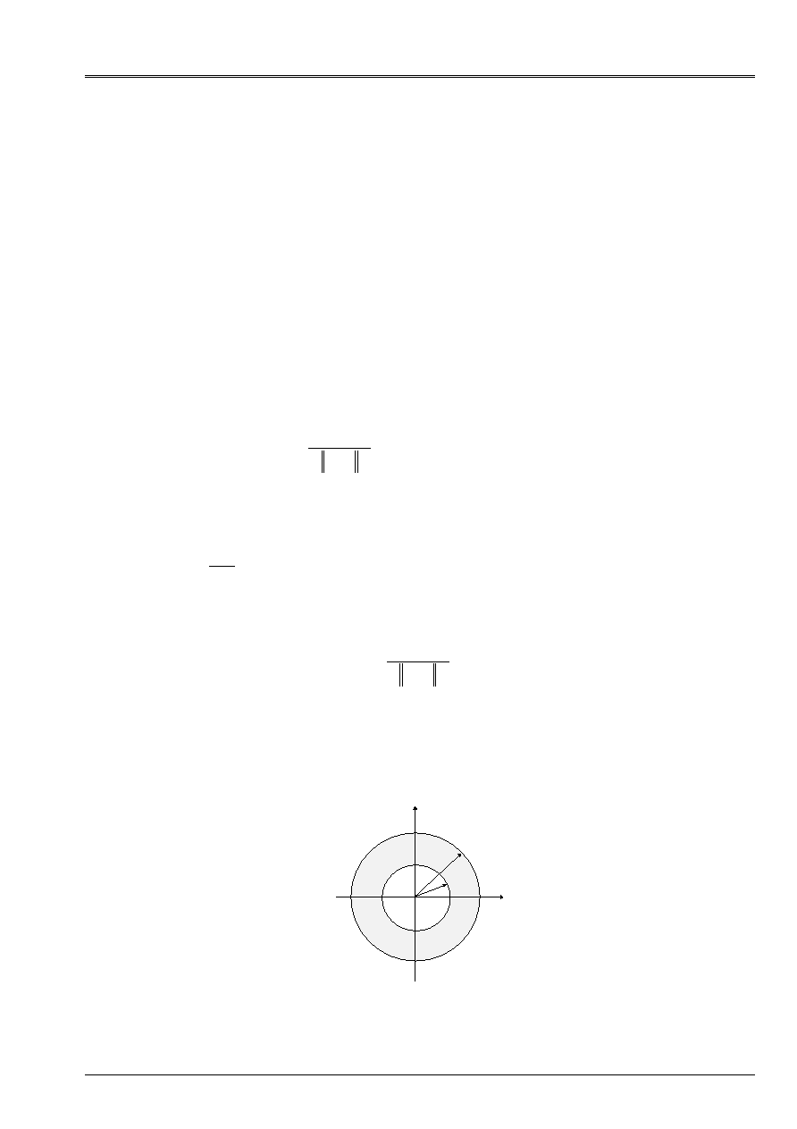
Code_Aster
®
Version
7.4
Titrate:
Calculation of the characteristics of a beam of cross section unspecified
Date:
01/09/05
Author (S):
J.M. PROIX, NR. LAURENT, P. HEMON, G. BERTRAND
Key:
R3.08.03-C
Page
:
33/42
Manual of Reference
R3.08 booklet: Machine elements with average fiber
HT-66/05/002/A
The function is considered
such as
1
on
I
. Matriciellement, one a:
[]
[]
=
T
[] []
v
v
T
=
[] []
=
T
Where
[]
is the vector whose components are related to form.
Under these conditions, the variational approximation of the weak formulation gives:
[]
[]
[] []
[]
[]
[]
[]
[]
K
B
F
T
B
T
I
I
I
+
=
+
=
0
Where one posed:
[]
[]
T
F v
v D
=
2
[] []
()
T
I
I
T v
v DLL
I
=
2
[]
[]
B
B
I
I
=
One can check that the condition on flow is checked:
[]
[] [] [] []
[]
[]
()
()
N DLL
DLL
D
D
D
F
T
B
DLL
I
I
I
T
T
T
T
I
I
I
I
=
=
+
= -
+
+
-
=
=
=
=
2
2
2
0
0
1
2
444
3
444
1 2
4 3
4
It is seen, with this new formulation, that the posed mathematical problem returns to a problem of
linear thermics with a particular loading. This is easily programmable in Code_Aster.
By applying the preceding method to a beam whose cross-section is the crown ranging between
radii
R
1
and
R
0
with
R
R
1
0
<
.
G
R
1
R
0
Code_Aster
®
Version
7.4
Titrate:
Calculation of the characteristics of a beam of cross section unspecified
Date:
01/09/05
Author (S):
J.M. PROIX, NR. LAURENT, P. HEMON, G. BERTRAND
Key:
R3.08.03-C
Page
:
34/42
Manual of Reference
R3.08 booklet: Machine elements with average fiber
HT-66/05/002/A
There is the following problem to solve:
= -
2
(
)
R
R
=
=
=
0
0
0
(
)
R
R
=
=
1
1
N DLL
R
1
2
02
=
The general solution of the problem is written
()
()
=
= -
+
+
R
R
With
R
B
2
2
ln
Here, one has
N
R E
R
1
= -
. From where
()
2
2
2
0
12
1
12
R
With
R
R
With
-
=
=
ln
. In addition, one
()
R
B
R
0
02
0
2
=
=
. Finally:
()
R
R
R
= -
+
2
02
2
2
.
One can now calculate
()
J
ds
=
+
2
2
1
1
. One has
1
12
02
2
2
= -
+
R
R
and
()
1
12
=
R
. All
made calculations, there is the conventional result:
(
)
J
R
R
=
-
2
04
14
Code_Aster
®
Version
7.4
Titrate:
Calculation of the characteristics of a beam of cross section unspecified
Date:
01/09/05
Author (S):
J.M. PROIX, NR. LAURENT, P. HEMON, G. BERTRAND
Key:
R3.08.03-C
Page
:
35/42
Manual of Reference
R3.08 booklet: Machine elements with average fiber
HT-66/05/002/A
Appendix 2 Determination of the constant of shearing of one
beam equivalent to a whole of parallel beams
A2.1 Position of the problem:
One clarifies here a method developed in the control
MACR_CARA_POUTRE
to obtain the coefficients
of shearing AY and AZ of a beam equivalent to a whole of disjoined beams (e.g. embedded posts
between two floors). This makes it possible for example to carry out models “skewers” of ships, it is with
to say condensed in only one beam.
For only one beam, the definition of the coefficients of shearing rests on the energy method [§2.1.3]:
the formulation is based on complementary energy due to shearing in the section.
The coefficient of shearing is:
[
]
K
dS
S
dS
S
CT
S
CT
=
1
G G
2
2
Note:
This expression is still valid in the case of a heterogeneous beam (G variable).
The distribution of shear stress in the section, for only one beam, is based on the formula of
Jourawski, [§2.1.1] which provides the distribution of shear stresses due to a shearing action in one
direction and only the average of shearings in the other direction.
The formula of Jourawski is written:
CT
m y
I B y V
=
()
()
with
()
m y
T B T dt
y
y
=
()
max
Quantity
()
m y
represent the static moment on behalf of section A included/understood enters
y
and
y
max
G
B (y)
y
Z
y
max
With
B
Then K can be written in the form:
K
I
S
m
y
GB
y Dy
y
y
=
G
()
()
2
2
2
max
Code_Aster
®
Version
7.4
Titrate:
Calculation of the characteristics of a beam of cross section unspecified
Date:
01/09/05
Author (S):
J.M. PROIX, NR. LAURENT, P. HEMON, G. BERTRAND
Key:
R3.08.03-C
Page
:
36/42
Manual of Reference
R3.08 booklet: Machine elements with average fiber
HT-66/05/002/A
The subjacent idea is that the section supports normal stresses resulting from the theory of the beams
of Euler, and whom one evaluates the effort of slip of A on B.
For a nonrelated section, like the section out of cut of a ship, the assumption of Jourawski cannot
to be made (except considering that all the section becomes deformed axially like the same beam with each
X-coordinate X). One cannot know a priori the distribution of shearings nor of the normal stresses in
each post. The following figure gives an idea of the cross-section of a ship jet engine:
Appear A2.1-a: Section of a ship jet engine
Code_Aster
®
Version
7.4
Titrate:
Calculation of the characteristics of a beam of cross section unspecified
Date:
01/09/05
Author (S):
J.M. PROIX, NR. LAURENT, P. HEMON, G. BERTRAND
Key:
R3.08.03-C
Page
:
37/42
Manual of Reference
R3.08 booklet: Machine elements with average fiber
HT-66/05/002/A
A2.2 Expression simplified of the coefficients of shearing
Assumption: the posts are embedded in the floors: the ship seen on side can be represented
like a whole of parallel posts embedded between two floors:
F
H
Appear A2.2-a: together of posts between two boards
This particular case is calculated: each post is a rectangular beam of section (the main axes
of inertia of the various posts are not colinéaires). H=3 with 4m.
The beams are embedded at the two ends. It is then necessary to seek a relation between an effort F imposed on
higher floor, and the displacement of this floor in the same direction, i.e. to calculate the rigidity of
this system in this direction.
A2.2.1 For a beam:
The method used is exposed for example in [bib11].
Beam fixed at an end and free with the other:
The system is isostatic and elastic. One wants to express displacement U (H) according to F and
.
Principle of Virtual Work is written:
F
H
U, X
v, y
F H v H
M
v
V
v DLL
v
M v
E I
v
V v
G S
F
O
H
F
R
(). ()
. ()
. ()
()
()
.
()
()
.
=
+
=
=
for any virtual displacement v, and a specific effort F in y=H, (here the normal effort is null).
F=1 is chosen, and one calculates successively displacements due to an effort F and a couple
in y=H. In
integrating the preceding expression, it is found that, under the effect F, displacement U real and rotation are worth:
U H
F H
E I
F H
G S
F H
E I
I.E.(internal excitation)
G H S
R
R
()
.
.
.
.
.
.
.
=
+
=
+
3
3
2
3
12
4
12
with
S
K S
R
=
.
and
()
.
.
H
F H
E I
= -
2
2
Under the effect of the moment
, one obtains:
U H
H
E I
()
.
.
= -
2
2
()
.
.
H
H
E I
=
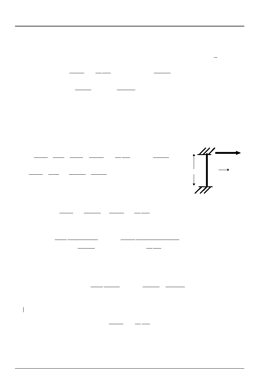
Code_Aster
®
Version
7.4
Titrate:
Calculation of the characteristics of a beam of cross section unspecified
Date:
01/09/05
Author (S):
J.M. PROIX, NR. LAURENT, P. HEMON, G. BERTRAND
Key:
R3.08.03-C
Page
:
38/42
Manual of Reference
R3.08 booklet: Machine elements with average fiber
HT-66/05/002/A
If the beam has a rectangular section of width B and thickness H, one obtains:
S
bhk
bh
R
=
=
5
6
for F imposed:
U H
F H
E bh
H
H
()
.
.
(
)
=
+
+
3
3
2
2
4 12
5
1
()
.
.
H
F H
E bh
= -
6
2
3
for
imposed:
U H
H
E bh
()
.
.
= -
6
2
3
()
.
.
H
H
E bh
=
12
3
Beam fixed at the two ends: (embedding slipping in y=H)
The system is hyperstatic degree 1.
One expresses displacement U (H) according to the hyperstatic unknown factors
F and
,
using the preceding results.
Under the effect F and
, displacement U real and rotation (null because of embedding) are worth:
F
H
U H
F H
E I
F H
GS
H
E I
F H
E bh
H
H
H
E bh
R
()
.
.
.
.
.
.
.
(
)
.
.
=
+
-
=
+
+
-
3
2
3
3
2
2
2
3
3
2
4 12
5
1
6
0
2
6
12
2
2
3
2
= -
+
= -
+
F H
I.E.(internal excitation)
H
E I
F H
E bh
H
E bh
.
.
.
.
.
.
.
The resolution of this system makes it possible to obtain U (H) according to F:
U H
F H
I.E.(internal excitation)
I.E.(internal excitation)
GH S
F H
E bh
H
H
F
I.E.(internal excitation)
H
I.E.(internal excitation)
GH S
U H
E bh
H
H
H
U H
K U H
R
R
()
.
.
.
(
)
()
.
(
)
()
. ()
=
+
=
+
+
=
+
=
+
+
=
3
2
3
3
2
2
3
2
3
3
2
2
12
1
12
1 12
5
1
12
1
1
12
1
1 12
5
1
One also finds this result by considering the matrix of rigidity of an “exact” element of beam with 2
nodes ([bib1] or [R3.08.01]). The term above corresponds exactly at the end of rigidity of sharp effort
only according to direction X:
(
)
K
I.E.(internal excitation)
H
I.E.(internal excitation)
GH S
I.E.(internal excitation)
GH kS
xx
R
=
+
=
=
12
1
1
12
12
3
2
2
Note:
The embed-free situation differs only from one coefficient (4 instead of 1):
U H
F H
E bh
H
H
()
.
.
(
)
=
+
+
3
3
2
2
4 12
5
1
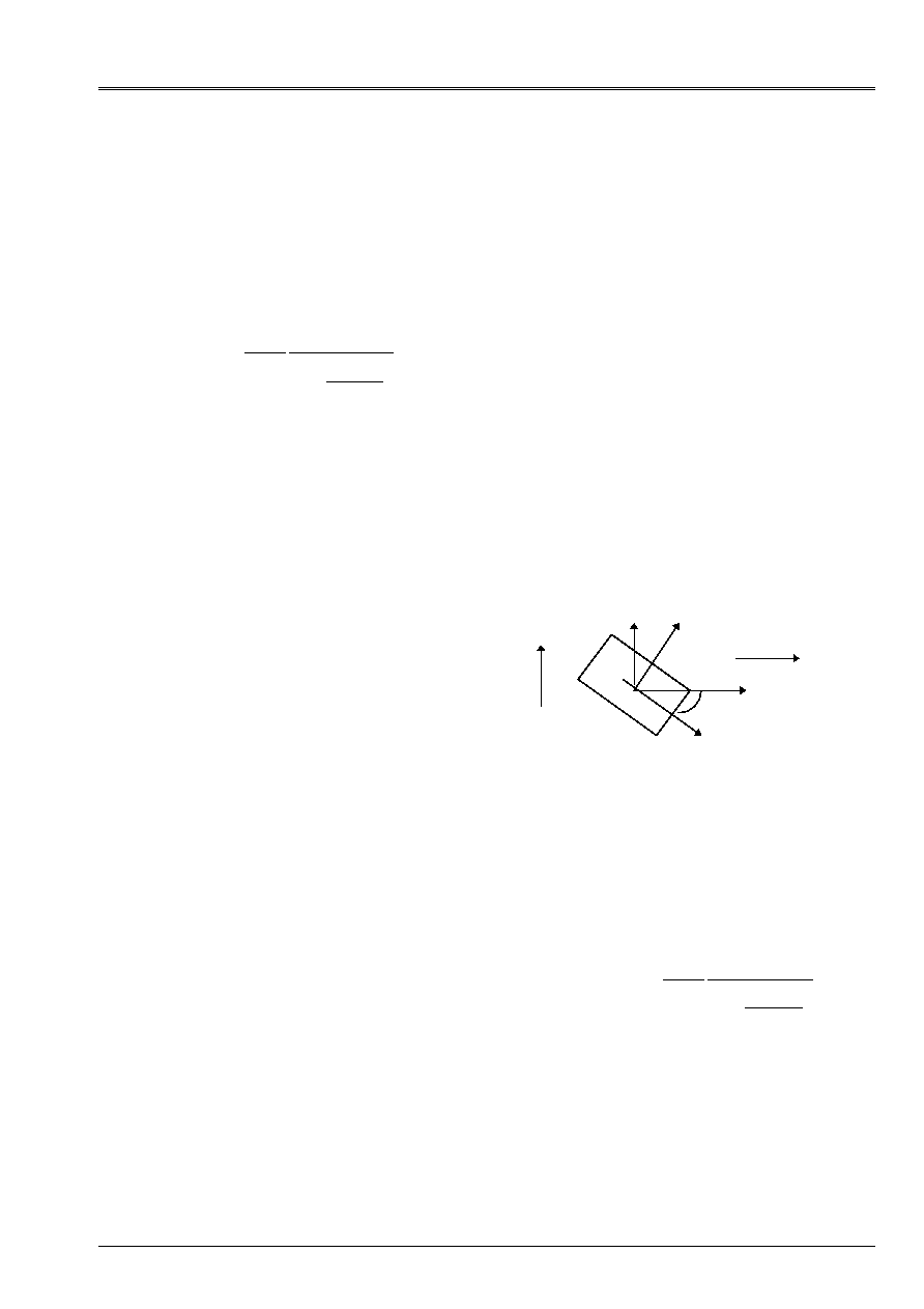
Code_Aster
®
Version
7.4
Titrate:
Calculation of the characteristics of a beam of cross section unspecified
Date:
01/09/05
Author (S):
J.M. PROIX, NR. LAURENT, P. HEMON, G. BERTRAND
Key:
R3.08.03-C
Page
:
39/42
Manual of Reference
R3.08 booklet: Machine elements with average fiber
HT-66/05/002/A
The two possibilities are offered in
MACR_CARA_POUTRE
:
·
the two ends are embedded (actually one is embedded, the other is embedded in a floor
mobile: slipping embedding)
·
the higher end is free (makes some in connection rotulée with the higher floor).
One can thus propose to express rigidity with the shearing action of each post in the form:
F
I.E.(internal excitation)
H
I.E.(internal excitation)
GH S
U H
U H
R
=
+
=
12
1
12
3
2
()
. ()
K
with
=
-
-
1
4
embedded embedded
embedded free
A2.2.2 For a whole of beams
The method consists in calculating the rigidity of each post in the preceding way, and to compare rigidity
of the whole to that of an equivalent beam embedded between two floors. For that one expresses the effort
total edge applied to the whole of the posts (for example in the direction y):
T
T
K U
y
I
y
y
=
=
~.
Each post having an unspecified orientation compared to the total axes, it is necessary for all to express them
efforts
T
I
in the total reference mark:
x1 and x2 indicating the main axes of inertia of
post I, sharp effort
T
I
in this reference mark is:
T
T
T
T
T
T
y
I
I
I
I
I
Z
I
I
I
I
I
=
+
= -
+
1
2
1
2
cos ()
sin ()
sin ()
cos ()
I
y
Z
X
1
X
2
Ty
Tz
Moreover, one supposes that total displacement U of the whole of the posts is uniform (components
U
y
and
U
y
) and must be colinéaire with the shearing action T. (what is not certain: couplings are possible if it
does not have there particular symmetries). This involves for the direction y:
U
U
U
U
I
y
I
I
y
I
1
2
=
=
cos ()
sin ()
and
T
K U
T
K U
I
I
I
I
I
I
1
1
1
2
2
2
=
=
.
.
one obtains:
(
)
(
)
T
K
K
U
T
T
K
K
U
K U
y
I
I
I
I
I
y
I
y
y
I
I
I
I
I
y
y y
=
+
=
=
+
=
1
2
2
2
1
2
2
2
cos ()
sin ()
cos ()
sin ()
~
with
~
K
I.E.(internal excitation)
H
I.E.(internal excitation)
GH S
y
R
=
+
12
1
12
3
2
in the same way in direction Z:
U
U
U
U
I
Z
I
I
Z
I
1
2
= -
=
sin ()
cos ()
thus
(
)
T
T
K
K
U
K U
Z
Z
I
I
I
I
I
Z
Z Z
=
=
+
=
1
2
2
2
sin ()
cos ()
~
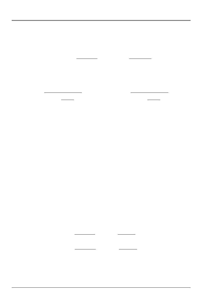
Code_Aster
®
Version
7.4
Titrate:
Calculation of the characteristics of a beam of cross section unspecified
Date:
01/09/05
Author (S):
J.M. PROIX, NR. LAURENT, P. HEMON, G. BERTRAND
Key:
R3.08.03-C
Page
:
40/42
Manual of Reference
R3.08 booklet: Machine elements with average fiber
HT-66/05/002/A
In addition, for the equivalent beam, one makes the assumption that rigidity with the shearing action S `expresses
even way that that of each beam:
(
)
T
K U
I.E.(internal excitation)
H
U
I.E.(internal excitation)
S H Gk
y
eq y
zeq
y
y
y
zeq
eq
yeq
y
=
=
+
=
12
1
12
3
2
with
In fact, it would have to be checked that energies due to the bending and the normal effort are quite negligible.
The two expressions of the shearing action lead to the expression of the coefficient of equivalent shearing:
K
I.E.(internal excitation)
GS H
I.E.(internal excitation)
H K
y
eq
Z
eq
eq
Z
eq
y
=
-
12
12
1
2
3
~
and in direction Z:
K
I.E.(internal excitation)
GS H
I.E.(internal excitation)
H K
Z
eq
y
eq
eq
y
eq
Z
=
-
12
12
1
2
3
~
A2.3 Method used in
MACR_CARA_POUTRE
By using the assumptions described previously, namely:
·
only rigidity due to the shearing action is taken into account in the calculation of the coefficients of shearing
·
the equivalent beam is embedded on the two floors
·
two design assumptions are to be envisaged concerning each post (embed-ball joint and embedded
embedded).
one can propose a method of calculation in
MACR_CARA_POUTRE
to obtain coefficients of
shearing are equivalent to a whole of beams of parallel axes, embedded in a floor with one of
their ends, and free with the other, or embedded at the other end.
Restrictions of use:
·
it is reasonable to place the equivalent beam on the center of gravity of the whole of the posts, and in
the main reference mark of inertia of the unit, to avoid the parasitic couplings
·
it is necessary to ensure the continuity of all the DDL of the equivalent beam (translation and rotation) with the DDL
floors (what modelizes the embedding of the beam in the floor), which forces to modelize it
floor in elements of hulls or, if it is with a grid in 3D, to connect it using beams or of plates.
A2.3.1 the method of calculation is as follows:
1) For each post, to make usual calculation by
MACR_CARA_POUTRE
geometrical characteristics and
coefficients of shearing of the section, in the main reference mark of inertia of each section (already
available)
2) Always for each section, calculation of rigidity to shearing (the user must provide H, distance enters
floors):
(
)
(
)
K
I.E.(internal excitation)
H
I.E.(internal excitation)
S H Gk
K
I.E.(internal excitation)
H
I.E.(internal excitation)
S H Gk
I
I
I
I
I
I
I
I
I
I
1
2
3
1
1
2
2
1
2
1
3
2
2
1
2
2
12
1
12
12
1
12
=
+
=
=
+
=
with
with

Code_Aster
®
Version
7.4
Titrate:
Calculation of the characteristics of a beam of cross section unspecified
Date:
01/09/05
Author (S):
J.M. PROIX, NR. LAURENT, P. HEMON, G. BERTRAND
Key:
R3.08.03-C
Page
:
41/42
Manual of Reference
R3.08 booklet: Machine elements with average fiber
HT-66/05/002/A
3) Calculation of rigidity equivalent to the whole of the beams:
(
)
~
cos ()
sin ()
K
K
K
y
I
I
I
I
=
+
1
2
2
2
(
)
~
sin ()
cos ()
K
K
K
Z
I
I
I
I
=
+
1
2
2
2
4) Calculation of the coefficients of shearing are equivalent:
K
I.E.(internal excitation)
GS H
I.E.(internal excitation)
H K
y
eq
Z
eq
eq
Z
eq
y
=
-
12
12
1
2
3
~
K
I.E.(internal excitation)
GS H
I.E.(internal excitation)
H K
Z
eq
y
eq
eq
y
eq
Z
=
-
12
12
1
2
3
~
knowing that
S
eq
,
I
y
eq
and
I
Z
eq
are already calculated by
MACR_CARA_POUTRE
.
For the key words of the control
MACR_CARA_POUTRE
, one needs that the user provides H, by the key word
LENGTH
, characteristics (constant) of the material (key word
MATERIAL
) and chooses the conditions with
limits by the key word
CONNECTION
:
CONNECTION: BALL JOINT
or
CONNECTION: EMBEDDING
This calculation is of course activated only if several
GROUP_MA
are defined by the user (indicating that the section
is made up of under disjoined parts).

Code_Aster
®
Version
7.4
Titrate:
Calculation of the characteristics of a beam of cross section unspecified
Date:
01/09/05
Author (S):
J.M. PROIX, NR. LAURENT, P. HEMON, G. BERTRAND
Key:
R3.08.03-C
Page
:
42/42
Manual of Reference
R3.08 booklet: Machine elements with average fiber
HT-66/05/002/A
Intentionally white left page.