
Code_Aster
®
Version
3
Titrate:
Forces of fluid blade in transitory calculation on modal basis
Date:
14/05/97
Author (S)
:
G. JACQUART
Key:
R5.06.05-A
Page:
1/18
Manual of Reference
R5.06 booklet: Dynamics in modal base
HP-51/96/079 - Ind A
Organization
: EDF/EP/AMV
Manual of Reference
R5.06 booklet: Dynamics in modal base
Document: R5.06.05
Forces of fluid blade in transitory calculation on basis
modal
Summary:
This document presents a numerical modeling of the forces of fluid blade which exist when two
mechanical systems, plunged in a fluid, vibrate with weak plays between them.
These non-linear forces comprise terms of acceleration which require a particular processing for
conventional explicit diagrams of integration.
An iterative diagram of type not fixes is proposed. It makes it possible to preserve the architecture of the explicit diagrams of
Code_Aster. These forces are established in the operator
DYNA_TRAN_MODAL
[U4.54.03].

Code_Aster
®
Version
3
Titrate:
Forces of fluid blade in transitory calculation on modal basis
Date:
14/05/97
Author (S)
:
G. JACQUART
Key:
R5.06.05-A
Page:
2/18
Manual of Reference
R5.06 booklet: Dynamics in modal base
HP-51/96/079 - Ind A
Contents
1 Introduction ............................................................................................................................................ 3
2 analytical Expression of the forces of fluid blade in a simple geometrical configuration ............. 4
2.1 Geometrical configuration .............................................................................................................. 4
2.2 Equations governing the behavior of the fluid .............................................................................. 4
2.3 Resolution of the fluid flow of blade with uniform profile ..................................................... 5
2.4 Resolution of the fluid flow of blade with parabolic profile ................................................. 6
3 Study of the dynamic behavior of a system to a degree of freedom in the presence of a blade
fluid ...................................................................................................................................................... 8
3.1 To launch of a mass slowed down by fluid blade with uniform profile ................................................... 8
3.2 To launch of a mass slowed down by fluid blade with parabolic profile ............................................ 10
4 Calculation of a system multi degrees of freedom locally subjected to forces of fluid blade ............. 13
5 Establishment of the non-linear forces of fluid blade ........................................................................... 15
5.1 Specific integration for the forces of fluid blade .................................................................... 15
5.2 Use of the forces of fluid blade in DYNA_TRAN_MODAL ............................................... 15
6 Model of fluid transition blade - shock ............................................................................................... 16
7 Conclusion ........................................................................................................................................... 17
8 Bibliography ........................................................................................................................................ 18

Code_Aster
®
Version
3
Titrate:
Forces of fluid blade in transitory calculation on modal basis
Date:
14/05/97
Author (S)
:
G. JACQUART
Key:
R5.06.05-A
Page:
3/18
Manual of Reference
R5.06 booklet: Dynamics in modal base
HP-51/96/079 - Ind A
1 Introduction
In the primary education circuit of the power stations ITEM the mechanical components are immersed in a fluid.
For some of this hardware, put in vibrations by the excitation of the primary education fluid, the presence of plays
relatively reduced leads to a more or less important closing of these plays even to contacts
in fluid environment. Numerical work was undertaken in Code_Aster to modelize the contact
dryness between mechanical structures. This work was established in a transitory operator of calculation
by modal recombination [bib3] and were validated by comparison with tests carried out on
model SOLID MASS [bib4].
The vibrations with contact in fluid environment show characteristics different from those
observed in air. When the play is filled, it creates a all the more important fluid flow as it
play is weak. This flow is at the origin of compressive forces acting on the structures
antagonists. Contrary to the configuration in air, where the structures interact by forces of
contact, only when the play is filled; in fluid environment this interaction is permanent and
depends in a non-linear way of the values on the play, normal speed of the structures and of their
acceleration. One will qualify the fluid locked up in the reduced type font of fluid blade; forces resulting from
compression of the fluid will be the forces of fluid blade.
For hardware like the fuel assemblies or the pencils of the bunches of
order these forces of fluid blade induce an amendment of the mechanical characteristics of
structure in air (mass, damping). The damping induced by the fluid blade can be
considerable, and it seems interesting to take it into account in a modeling of this hardware.
We present, in this report/ratio, a simple geometrical configuration, where one can integrate
the flow in the fluid blade realizing certain assumptions on the profile of the flow and them
losses of load at the edges. We determine thus the compressive forces exerted by the fluid on
structure and let us release a general form of their expression according to the play, speed and of
acceleration relative normals between the structures.
We build case-tests of reference on a system to a degree of freedom which illustrate it
behavior of a mechanical system subjected to a force of fluid blade.
The numerical establishment of these non-linear forces in Code_Aster is then detailed. It
require the use of a fixed algorithm of point to find accelerations generalized.
Code_Aster
®
Version
3
Titrate:
Forces of fluid blade in transitory calculation on modal basis
Date:
14/05/97
Author (S)
:
G. JACQUART
Key:
R5.06.05-A
Page:
4/18
Manual of Reference
R5.06 booklet: Dynamics in modal base
HP-51/96/079 - Ind A
2
Analytical expression of the forces of fluid blade in one
simple geometrical configuration
One proposes to determine in an analytical way here the forces being exerted on a structure vibrating
in an incompressible fluid in the vicinity of a motionless wall.
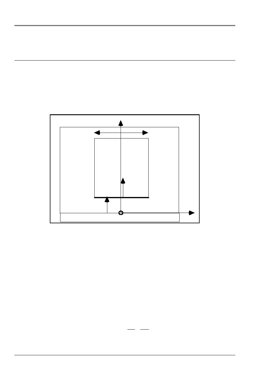
2.1 Configuration
geometrical
A problem of plane flow in the case of is placed (invariant in the direction there of [2.1-a]).
A solid body
is plunged in a fluid
F
. The solid has a plane face
of width 2 L
parallel in the yOz plan and vibrates in the vicinity of a wall fixes parallel with this plan.
Z
X
X
X
·
F
O
2L
y
Appear 2.1-Error! Argument of unknown switch. : Geometrical configuration of the fluid blade
2.2
Equations governing the behavior of the fluid
The problem is supposed invariant by translation according to the axis y, one is thus brought back to a problem
two-dimensional.
Speeds in the fluid will be noted:
() (
)
(
)
v
X
Z
T
X Z T
X Z T
=
+
U.
W.
One will note
X Z
,
, space co-ordinates eulériennes of the fluid, and
X X X
,
!!!
variables
Lagrangian defining the position, speed and acceleration of the solid.
The incompressible fluid being supposed, the components speeds must check:
div
X
Z
()
U
W
v
=
+
=
0
0
that is to say

Code_Aster
®
Version
3
Titrate:
Forces of fluid blade in transitory calculation on modal basis
Date:
14/05/97
Author (S)
:
G. JACQUART
Key:
R5.06.05-A
Page:
5/18
Manual of Reference
R5.06 booklet: Dynamics in modal base
HP-51/96/079 - Ind A
The fluid also checks the Navier-Stokes equations:
()
()
µ
v
v
v
v
T
grad
grad
+
+
- =
p
.
2
0
In the fluid blade one will suppose that the profile according to
X
component
W
field speed is
of invariant form compared to
Z
. That amounts supposing that it can be written in the form of one
function with separate variables:
(
)
()
W,
W. (,)
X Z T
Z T
X T
=
One in general considers two rather simple assumptions of profile:
·
a uniform profile speed,
·
a profile speed parabolic or flow of One tenth of a poise, valid for speeds
W
weak,
2.3
Resolution of the fluid flow of blade with uniform profile
The flow according to
Z
does not depend on
X
:
(
)
()
W,
W,
X Z T
Z T
=
One neglects in that the effects of viscosity of the fluid in the blade.
Let us write the relation of incompressibility of the fluid, integrated on the thickness of the fluid blade:
[]
()
(U
W).
,
U
W
X
Z
dx
Z
Z
dx
X
X
X
+
=
+
=
0
0
0
0
0
that is to say
.
The boundary conditions are:
()
()
U
!
U
X
X
=
=
and
0
0
,
one thus obtains
()
W
!
Z
Z
X
X
= -
who gives by integration and by noticing that
()
W 0
0
=
:
()
W Z
X
X Z
= -
!
One then deduces immediately the fields from them speed:
()
()
()
()
W X, Z
W Z
X
X Z
U X, Z
U X
X
X X
=
= -
=
=
!
!
Code_Aster
®
Version
3
Titrate:
Forces of fluid blade in transitory calculation on modal basis
Date:
14/05/97
Author (S)
:
G. JACQUART
Key:
R5.06.05-A
Page:
6/18
Manual of Reference
R5.06 booklet: Dynamics in modal base
HP-51/96/079 - Ind A
By using the Navier-Stokes equation to describe the behavior of the fluid and by projecting it on
the axis
Z
, then by replacing the expressions of
U
and of
W
established higher, and while placing itself in
the assumption of a thin blade of fluid like by considering assumptions of losses of loads
[bib2], one can show [bib5] that the fluid force has two expressions different according to the sign from
!X
:
if
!X
<
0
:
F
L Y X
X
L Y X
X
= -
+
2
3
4
3
3
3
2
…!!
…!
if
!X
>
0
:
F
L Y X
X
L Y X
X
= -
-
2
3
2
3
3
3
2
…!!
…!
One can give a general expression of the fluid force for the uniform profile in the form:
F
X
X
X
X
X X
X
= + +
. !!
. !
!. !
2
2
For the uniform profile, one a:
= -
=
= -
2
3
1
3
3
3
3
.
.
.
L Y
L Y
L Y
2.4
Resolution of the fluid flow of blade with parabolic profile
One gives at the horizontal speed
W
a parabolic profile which has as an expression:
(
)
(
)
()
W X, Z, T
a. X. X X .W Z, T
=
-
,
()
W Z
being mean velocity in the blade and
has
X
=
6
2
Let us write the relation of incompressibility of the fluid, integrated on the thickness of the fluid blade:
[]
()
[
]
U
X
W
Z dx
U
W Z
Z
a. X.(X
X) dx
X
X
X
+
=
+
-
=
.
0
0
0
0
0
,
that is to say
.

Code_Aster
®
Version
3
Titrate:
Forces of fluid blade in transitory calculation on modal basis
Date:
14/05/97
Author (S)
:
G. JACQUART
Key:
R5.06.05-A
Page:
7/18
Manual of Reference
R5.06 booklet: Dynamics in modal base
HP-51/96/079 - Ind A
The boundary conditions give:
()
()
U
!
U
X
X
=
=
and
0
0
, the expression is thus obtained:
()
W
!
Z
Z
X
X
= -
who gives by integration and by considering that
()
W 0
0
=
:
()
W
!
Z
X
X Z
= -
One then deduces immediately the fields from them speed:
(
)
()
(
)
(
)
W,
.(
). W,
.(
). !
U,
.
.
!
X Z T
X X X has
Z T
X X X
X
X Z
X Z T
X
X
X
X
X
=
-
= -
-
= -
-
6
3
2
3
2
3
By using the Navier-Stokes equation to describe the behavior of the fluid and by projecting it on
the axis
Z
, then by replacing the expressions of
U
and of
W
established higher, and while placing itself in
the assumption of a thin blade of fluid as well as assumptions of losses of loads [bib2], one can
to show [bib6] that the fluid force in the case of a parabolic profile has two different expressions
according to the sign of
!X
:
if
!X
<
0
:
F
L Y X
X
L Y
X
X
L Y X
X
= -
-
+
2
3
24
3
24
15
3
3
3
3
2
…!!
…. !
…!
if
!X
>
0
:
F
L Y X
X
L Y
X
X
L Y X
X
= -
-
-
2
3
24
3
2
5
3
3
3
3
2
…!!
…. !
…!
One can give a general expression of the fluid force in the form:
F
X
X
X
X
X
X
X X
X
= + +
+
. !!
. !
. !
!. !
2
3
2
with the formulated assumptions (parabolic profile), the coefficients are worth:
= -
=
= -
= -
2
3
3
5
24
3
3
3
3
3
.
.
….
.
L Y
L Y
L Y
L Y
The expression of the fluid force above thus represents the most complete form and is that
established in Code_Aster.
Code_Aster
®
Version
3
Titrate:
Forces of fluid blade in transitory calculation on modal basis
Date:
14/05/97
Author (S)
:
G. JACQUART
Key:
R5.06.05-A
Page:
8/18
Manual of Reference
R5.06 booklet: Dynamics in modal base
HP-51/96/079 - Ind A
3
Study of the dynamic behavior of a system to one
degree of freedom in the presence of a fluid blade
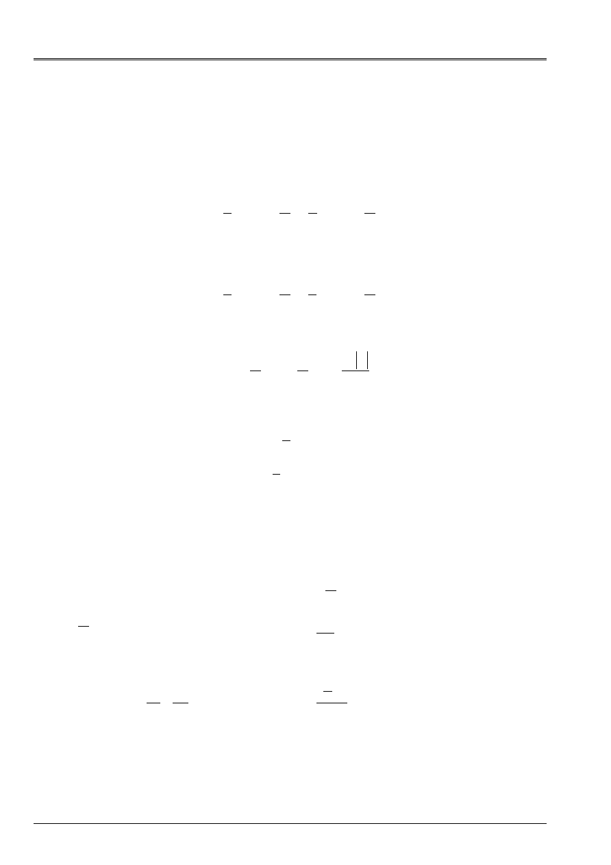
This chapter aims at integrating in an quasi-analytical way a system with fluid blade into a ddl, and serves as
references to tests SDND110A [V5.01.110] and SDND111A [V5.01.111].
Z
X
X
Xo
·
F
O
2L
M
Appear 3-Error! Argument of unknown switch. : Mass deadened by a fluid blade
One will consider the system without rigidity above nor external force applied.
The mass has an initial speed -
!X
0
, and a position
X
0
. One seeks to determine the position
of stop of the mass, evolution of the force of reaction. The equation of the system with the 2 assumptions of
profile: uniform and parabolic is as follows:
(
)
(
)
MR. X
X
X
X
X
X
X
X X
X
X T
X
X T
X
.
!!
. !!
. !
. !
!. !
!
!
= + +
+
=
=
=
= -
2
3
2
0
0
0
0
3.1
To launch of a mass slowed down by fluid blade with uniform profile
For the uniform mode, the differential equation governing the movement of stop of the mass is written
the following way:
MR. X
X
X
X
X
.
!!
. !!
. !
= +
2
.
One can find in [bib1] an analytical resolution whose we will point out the main results here.
By integrating once the differential equation, one obtains an expression the speed of the projectile in
function of its position:
!
! .
.
X
X
X
X
X
X
M
= -
+
+
=
0
0
0
2
2
where
While integrating once again compared to time this differential equation it comes:
T
X
X
X
X
X
Log XX
X
X
=
+
- +
+
-
1
2
1
1
0
0
0
2
0
0
2
0
! .
.
.

Code_Aster
®
Version
3
Titrate:
Forces of fluid blade in transitory calculation on modal basis
Date:
14/05/97
Author (S)
:
G. JACQUART
Key:
R5.06.05-A
Page:
9/18
Manual of Reference
R5.06 booklet: Dynamics in modal base
HP-51/96/079 - Ind A
There is thus an implicit definition of the displacement of the mass in the course of time. One can release
following properties of this movement:
·
the solid can touch the obstacle only at the end of an infinite time,
·
the solid approaches at infinitely slow speed of the obstacle.
The total fluid force has as an expression:
()
(
)
F
X
. MR. X
X
X
X
X
fluid
=
+
+
2
0
2
0
0
4
3
5
.
.
! .
.
Its maximum value is obtained by cancelling the derivative of this function. It is reached in
X
F max
=
3
2
and is worth
F
MR. X
X
X
Max fluid
=
+
8 3
5
3
5
02
0
0
4
.
.
.
! .
.
The numerical values considered for calculations are:
M
= 1000 kg
2L
= 100 mm
X
0
= 6 mm,
!X
0
= - 0.1 m/s
F
= 1000 kg/m
3
= 10
6
Coefficients
,
are calculated according to the formula of paragraph 2.3 and are worth in this case:
= 0.0833,
= 0.1666
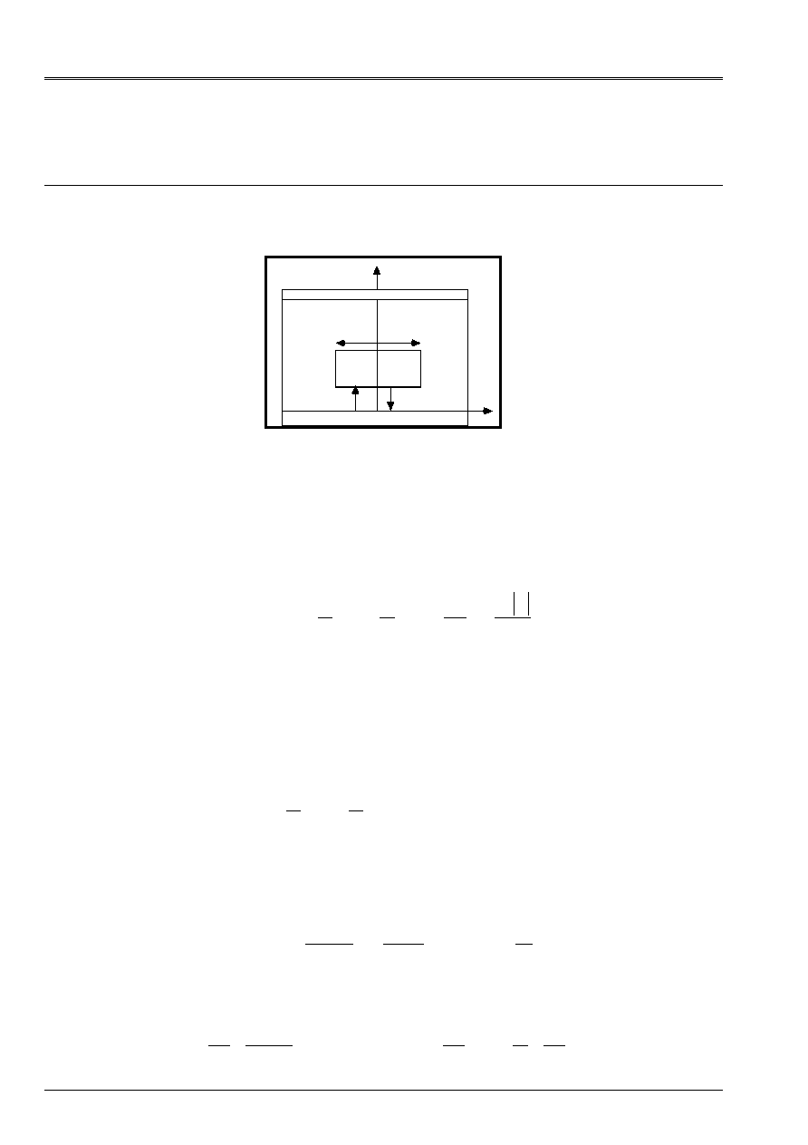
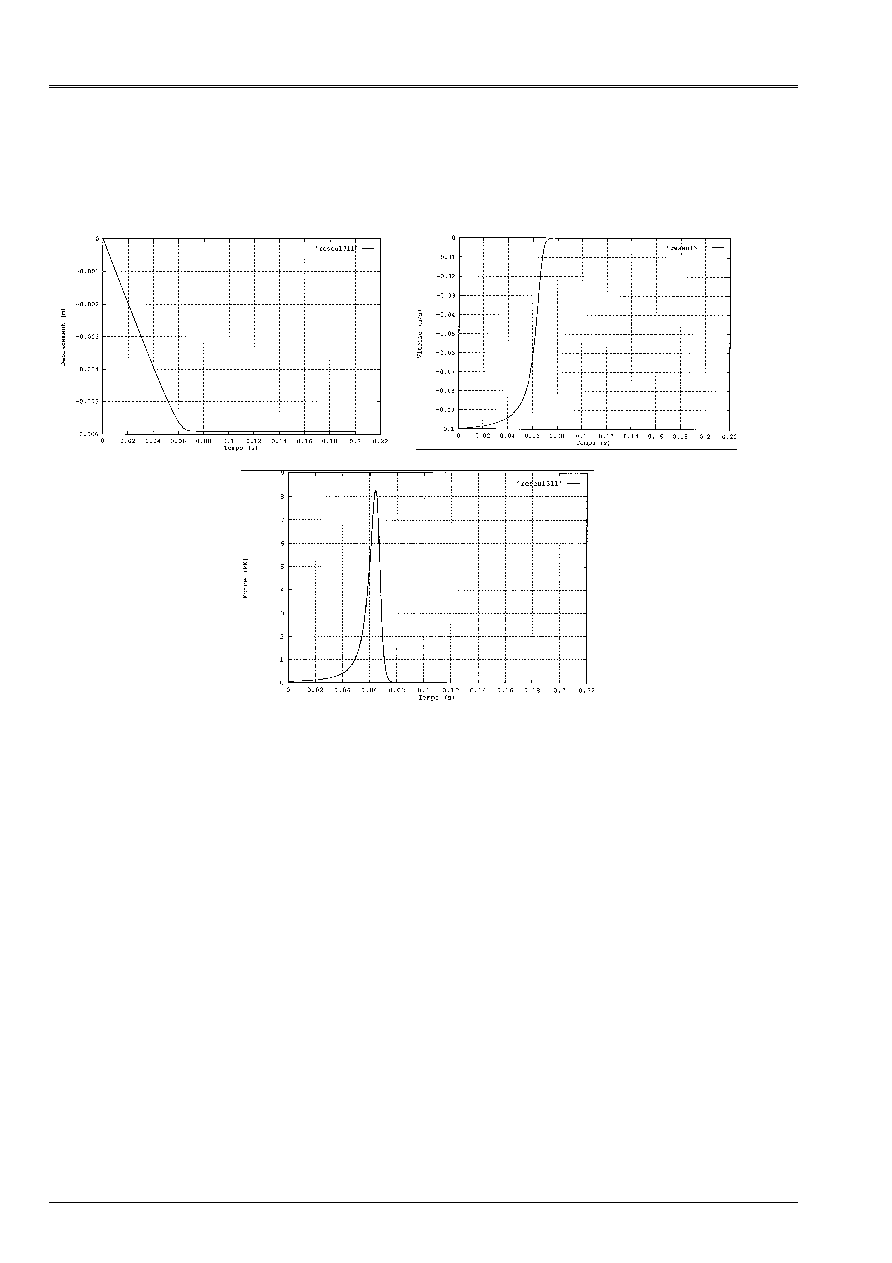
One can observe below displacement, the speed of the mass and the fluid force which it undergoes.
behavior of the mass is rather similar to that observed for the parabolic mode. The force
fluid maximum, given in an analytical way in the preceding paragraph, is worth in this case 8768 NR.
The mass in this case approaches in an asymptotic way of the wall and reaches it only at the end of one
infinite time.
Code_Aster
®
Version
3
Titrate:
Forces of fluid blade in transitory calculation on modal basis
Date:
14/05/97
Author (S)
:
G. JACQUART
Key:
R5.06.05-A
Page:
10/18
Manual of Reference
R5.06 booklet: Dynamics in modal base
HP-51/96/079 - Ind A
Note:
On the graph, at the end of the 0,2 S of calculation it remains a distance from 1.e-6 m to the wall.
3.2
To launch of a mass slowed down by fluid blade with parabolic profile
The analytical resolution of the differential equation governing the behavior of the mass is not any more
possible. One proposes to determine in an external way with any computer code, the dynamic response
this system with a ddl in the presence of a fluid blade. That gave place to the development of one
program dedicated FORTRAN, developed with this occasion.
As we established in the preceding paragraph, the force of reaction of the fluid blade takes
the following general form:
F
X
X
X
X
X
X
X X
X
fluid
= + +
+
. !!
. !
. !
!. !
2
3
2
The dynamic equation to which this system is subjected is as follows:
MR. X K X
F
X
X
X
X
X
X
X X
X
ext.
.
!!
.
. !!
. !
. !
!. !
+
=
+ + +
+
2
3
2
We propose a resolution by a temporal diagram of integration of the dynamic problem.
The expression of the second member is nonconventional because it utilizes acceleration. One proposes
to use an explicit diagram of integration, which requires the expression of
!!X
, according to
X X
,
!
. It
is thus necessary to rewrite the system in the form:
M
X
X
K X
F
X
X
X
X
X X
X
T
T
T
ext.
T
T
T
T
T
T
T
-
+
=
+ +
+
.
!!
.
. !
. !
! . !
2
3
2

Code_Aster
®
Version
3
Titrate:
Forces of fluid blade in transitory calculation on modal basis
Date:
14/05/97
Author (S)
:
G. JACQUART
Key:
R5.06.05-A
Page:
11/18
Manual of Reference
R5.06 booklet: Dynamics in modal base
HP-51/96/079 - Ind A
We will use the diagram of Euler modified to integrate this equation in time:
X X
0
0
,
!
given to T
0
,
To repeat
!!
.
. !
. !
! . !
!
!
.
!!
.
!
X
F
K X
X
X
X
X
X X
X
M
X
T
T
dt
X
X
dt X
X
X
dt X
I
ext.
I
I
I
I
I
T
I
I
I
I
I
I
I
I
I
I
I
=
-
+ +
+
-
= +
=
+
=
+
+
+
+
+
2
3
2
1
1
1
1
as long as
T
T
I
end
+
<
1
For the type of non-linearities considered, one does not have criterion of stability a priori of the diagram
of integration. One thus made sure by a study of convergence by decreasing the pitch of time of
calculation which the results obtained were stable.
Coefficients
,
and
are calculated according to the formula of paragraph 2.4 and are worth in this case:
= 0.0833,
= 0.19992 and
= 0.9996. 10
6
and M masses it = 1000 kg
Code_Aster
®
Version
3
Titrate:
Forces of fluid blade in transitory calculation on modal basis
Date:
14/05/97
Author (S)
:
G. JACQUART
Key:
R5.06.05-A
Page:
12/18
Manual of Reference
R5.06 booklet: Dynamics in modal base
HP-51/96/079 - Ind A
One can observe below displacement, the speed of the mass and the fluid force which it undergoes. One
note that it preserves a speed close to that initial before being sufficiently close to
wall. Then it undergoes an important fluid force which dissipates all the kinetic energy of the mass.
mass does not touch the wall, but preserves an asymptotic distance at the wall, which is worth 0.098 Misters.

Code_Aster
®
Version
3
Titrate:
Forces of fluid blade in transitory calculation on modal basis
Date:
14/05/97
Author (S)
:
G. JACQUART
Key:
R5.06.05-A
Page:
13/18
Manual of Reference
R5.06 booklet: Dynamics in modal base
HP-51/96/079 - Ind A
4 Calculation of a system multi degrees of freedom subjected
locally with forces of fluid blade
A means of simulating the forces of fluid blade is to introduce them like non-linear forces into
the algorithm of modal recombination
DYNA_TRAN_MODAL
[bib3] [U4.54.03], allowing to calculate
dynamics of a mechanical system by carrying out a projection on the basis of its free mode.
The temporal algorithms of Code_Aster treating the non-linear forces are the explicit diagrams
of Euler and Devogelaere. We saw in the preceding chapter that the intrinsic form of the forces
of fluid blade a problem for the resolution with an explicit diagram poses. An amendment of
the algorithm
DYNA_TRAN_MODAL
a suitable processing of the forces of fluid blade allows.
The direct dynamic problem discretized by finite elements is written:
MR. X
C X
K X
F
F
X X X
. !!
.
.
()
(
! !! )
T
T
T
ext.
fluid
T
T
T
T
+
+
=
+
Technique used in the operator
DYNA_TRAN_MODAL
consist in projecting on the basis of system
linear and to maintain the forces non-linear with the second member.
The projected dynamic system takes the form:
T
T
T
T
T
T
T
ext.
T
fluid
T
T
T
T
….
!!
….
!
….
.
()
.
(.
.
! . !! )
M
C
K
F
F
+
+
=
+
éq
4-1
The methods of explicit integration require to determine
!!
T
knowing
T
T
,
!
and
possibly their former values.
One thus sees in the expression of the system [éq 4-1] above that
!!
T
is not given in way
clarify according to
T
T
,
!
. From this moment, one proposes to use a method of point fixed
to obtain generalized accelerations.
This is obtained by applying the following operations:
!!
!! ,
,
!
0
1
T
T
T
T
=
-
given
to repeat until convergence:
[
]
(
)
!!
.
.
.
(.
.
! . !! )
.
()
….
!
….
I
T
T
T
fluid
T
T
it
T
ext.
T
T
T
T
T
+
-
=
+
-
-
1
1
M
F
F
C
K
convergence is tested by
!!
!!
.
!!
I
T
it
it
+
-
<
1
.
Unfortunately this technique of iteration of the fixed point is not necessarily convergent. For
that, it is necessary that the linear operator reiterated either contractor. However for thicknesses of fluid blade low,
the terms of inertias can be very important and thus prevent the convergence of
iterations of fixed point. It is thus not established such as it in the operator
DYNA_TRAN_MODAL
.
We will analyze more in detail the operator
T
fluid
T
T
T
.
(.
.
! . !! )
F
, to extract some
diagonal part and to make it pass to the first member.
In a node
N
comprising an effect of blade fluid, the fluid inertia will be expressed in the form,
linear in acceleration:
F
X
X
inertia
N
N
=
. !!

Code_Aster
®
Version
3
Titrate:
Forces of fluid blade in transitory calculation on modal basis
Date:
14/05/97
Author (S)
:
G. JACQUART
Key:
R5.06.05-A
Page:
14/18
Manual of Reference
R5.06 booklet: Dynamics in modal base
HP-51/96/079 - Ind A
Sizes
!! ,
X X
N
N
are expressed in a local reference mark. They are thus obtained by one
operation of extraction
P
total assembled vector, followed by a series of rotations
R
N
to obtain
in the local reference mark, followed by an extraction
E
N
normal component.
One will note these operations in a matric way
!!
.
.
!!
X
E R P X
N
N
N
=
.
In a similar way, the local inertia must be turned over in the physical reference mark and to dimension
vector assembled, before being projected on the basis
. These operations can be noted of
matric way:
{}
T
T
T
N
NT
fluid
.
.
.
.
.
F
P R
E
F
=
-
1
The vector of the generalized forces representing the component of inertia of the fluid blade is:
T
N
T
T
N
N
T
N
N
X
.
.
.
.
.
.
….
!!
F
P R
E E R P
=
-
1
.
In the general case, one cannot determine once for all the value of this matric product because it
thus depends on the local reference mark of the position of the structure compared to the fluid blade. One proposes
to use an approximation of this matrix in the form:
m
P P
'
.
.
.
T
T N
T
T
X
=
To return the operator of point contractor it fixes is enough to modify the matrix of mass of the operator
of iteration by cutting off the matrix to him
me
. That amounts adding to him in fact of the mass bus
is
negative.
One will use in the algorithm of Euler modified for the taking into account of the effects of fluid blade,
the algorithm of point fixes opposite:
!!
!!
0
1
T
T
=
-
to repeat until convergence:
(
!!
.
. diag (')
.
.
(.
.
! . !! )
.diag (').
!!
.
()
….
!
….
I
T
T
N
nodes fluid
T
fluid
T
T
it
N
nodes fluid
it
T
ext.
T
T
T
T
T
+
-
=
-
-
+
-
-
1
1
M
m
F
m
F
C
K
convergence is tested by
!!
!!
.
!!
I
T
it
it
+
-
<
1
, where
is a precision given for the stop of
iterations.
The parameter
,
chosen higher than one, is used to guarantee the character contracting of the iterations of
not fixes. In practice, one chooses for value
= 10 what seems to guarantee convergence in all
the cases observed, one can possibly modify this parameter in the event of problems of convergence.
There is not theoretical result giving a best alternative for
. One will be possibly led to
to modify this value according to the importance of the non-linear forces in the response of the system, for
to improve convergence of the calculation of acceleration.

Code_Aster
®
Version
3
Titrate:
Forces of fluid blade in transitory calculation on modal basis
Date:
14/05/97
Author (S)
:
G. JACQUART
Key:
R5.06.05-A
Page:
15/18
Manual of Reference
R5.06 booklet: Dynamics in modal base
HP-51/96/079 - Ind A
5
Establishment of the non-linear forces of fluid blade
5.1
Specific integration for the forces of fluid blade
The forces of fluid blade compatible with the diagram of integration are named
“EULER”
and
“ADAPT”
in the operator
DYNA_TRAN_MODAL
. The processing of the forces of fluid blade is not activated
that when fluid blades are present in the model what guarantees a hold of
performances of the algorithms
EULER
and
DEVOGE
former, and allows to use a blade in the case of
fluid, a specific option but preserving nevertheless non-linearities and the functionalities
existing of the initial algorithm.
5.2
Use of the forces of fluid blade in
DYNA_TRAN_MODAL
The forces of fluid blade are designed to function like non-linearities of shock, i.e.,
that an effect of blade fluid can act between a point of a structure and a fixed obstacle, or between two
antagonistic points of two structures.
The parameters of fluid blade are thus provided in the key word factor
SHOCK
of the operator
DYNA_TRAN_MODAL
. Syntax under this key word will be as follows:
SHOCK:
(
….
RIGI_NOR: KN [r8]
….
LAME_FLUIDE: /
“NOT”
[DEFECT]
/
item
[KN]
ALPHA
:
/
0.
[DEFECT]
/
[R8]
BETA:
/
0.
[DEFECT]
/
[R8]
CHI
:
/
0.
[DEFECT]
/
[R8]
DELTA
:
/
0.
[DEFECT]
/
[R8]
)
The key word
LAME_FLUIDE
allows to specify if the interaction enters the node and the obstacle or between
two nodes takes place in the presence of a fluid blade. By defect the connection is supposed of contact type
dryness.
Key words
ALPHA
,
BETA
,
CHI
,
DELTA
allow to describe the form of the non-linear force of
fluid blade, their values correspond to the coefficients
,
,
and
are mentioned in the chapter
[§2]. They make it possible to define in the choice a uniform or parabolic profile.

Code_Aster
®
Version
3
Titrate:
Forces of fluid blade in transitory calculation on modal basis
Date:
14/05/97
Author (S)
:
G. JACQUART
Key:
R5.06.05-A
Page:
16/18
Manual of Reference
R5.06 booklet: Dynamics in modal base
HP-51/96/079 - Ind A
6
Model of fluid transition blade - shock
The studies justifying the development of the forces of fluid blade comprise situations where
structure vibrates in the presence of fluid blade and can even according to certain conditions of excitation outward journey
until the dry contact with the obstacle in the event of fluid film rupture.
This situation is particularly difficult to manage numerically from the nature of the expression of
forces of fluid blade used. In fact, one is obliged to consider a physical limit of validity with
the expression of these forces of fluid, limiting blade beyond which it is necessary to forward towards conditions
of mechanical contact (dry) between the structures.
One thus introduces consequently occasion the concept fluid thickness of blade limits beyond
which the fluid model of blade only is not valid any more, and the blade becomes in fact incompressible.
To preserve at the force of reaction (fluid blade and contact) a continuous character, we introduced
a weight function
()
F
ponder
D
N
who allows continuously to forward force of repulsion
of fluid blade to a force of repulsion of dry the contact type.
()
()
()
[]
F
F
F
,
ponder
ponder
ponder
D
D
D
D
D
C
D
N
N
N
N
N
N
=
=
0
0
1
0
0
if
if
of continuity
for
In the area of transition
[]
D
N
0,
, the force of reaction is written:
()
(
)
()
(
)
(
)
F
D
D D D
D
D
D
reaction
N
N
N
N
N
N
N
=
×
+ -
×
-
F
F
,
! !!
F
Fchoc
,
!
ponder
fluid
ponder
1
The boundary layer
is dynamically given with heuristics according to the formula:
(
)
=
F
! !!
fluid
D D D
K
N
N
N
NR
éq 6-1
If this boundary layer is reached or exceeded
D
N
by the wall of the structure one enters one
phase of transition towards the shock. The limiting value thickness is then filed and the model of
transition is used until
D
N
becomes again
.
One explains physically the choice of the formula [éq 6-1] to determine the fluid thickness of blade in
considering that in this situation the fluid force of blade is such as it can deform the structure
on its stiffness of shock and thus the fluid blade in it even becomes incompressible, from where need for
to forward towards the model of force of shock.
Note: Use of the forces of fluid blade with the model of transition
The fluid model of transition - shock was introduced in a systematic way. As soon as one introduces
a fluid force of blade, one can forward towards the shock. It is thus necessary systematically
to introduce a stiffness of shock
K
NR
(key word
RIGI_NOR
). If one never wishes not to forward
towards a dry contact (mainly for case-tests) it will be necessary to take a value of
K
NR
very large (10
15
).

Code_Aster
®
Version
3
Titrate:
Forces of fluid blade in transitory calculation on modal basis
Date:
14/05/97
Author (S)
:
G. JACQUART
Key:
R5.06.05-A
Page:
17/18
Manual of Reference
R5.06 booklet: Dynamics in modal base
HP-51/96/079 - Ind A
7 Conclusion
This document describes the expression of the fluid forces which are exerted when a structure vibrates with
vicinity of a plane wall, in an incompressible fluid at rest (put in flow by
movement of the structure). These forces are called forces of fluid blade.
For two assumptions of profile of flow in the blade, an analytical form of the force is established.
The latter depends in a non-linear way of acceleration, the speed and the position of
structure compared to the obstacle.
For a system with a degree of freedom with initial speed deadened by a fluid blade, a calculation
analytical could be carried out with a uniform profile. For the other profile, like configurations
of system masses spring, a numerical integration was necessary. One could analyze on these
calculations the behavior of the fluid blade, which introduces in particular a strong damping.
The processing of these forces for systems with several degrees of freedom resulted in modifying
the explicit algorithm of integration on the basis of modal
DYNA_TRAN_MODAL
to integrate correctly
the ram effect of these forces in Code_Aster.

Code_Aster
®
Version
3
Titrate:
Forces of fluid blade in transitory calculation on modal basis
Date:
14/05/97
Author (S)
:
G. JACQUART
Key:
R5.06.05-A
Page:
18/18
Manual of Reference
R5.06 booklet: Dynamics in modal base
HP-51/96/079 - Ind A
8 Bibliography
[1]
J. CHRIGUI - “Contribution to the study of the shocks of structures in the presence of fluid”, Thesis
presented at the INSTN July 12, 1986
[2]
I.E. IDEL' CIK “Memorandum of the losses of loads”, Eyrolles Paris Editor, 1969, Collection of
And Test research center of CHATOU
[3]
G. JACQUART - “Operator
DYNA_TRAN_MODAL
“, Documentation of Aster Use
[U4.54.03], Version 2.7
[4]
D. BOSSELUT, G. JACQUART, D. BANC - “Vibrations with shocks. Experimental validation
biaxial on the MASSIVE test rig ", Report/ratio EDF DER HP-61/92.158
[5]
G. JACQUART - “Modeling of the forces of fluid blade”, Report/ratio EDF DER HP-61/94.159/A