This document explains how to use Inkscape's Interpolate extension
Introduction
Interpolate does a linear interpolation between two or more selected paths. It basically means that it “fills in the gaps” between the paths and transforms them according to the number of steps given.
To use the Interpolate effect, select the paths that you wish to transform, and choose from the menu.
Before invoking the effect, the objects that you are going to transform need to be paths. This is done by selecting the object and using or Shift+Ctrl+C. If your objects are not paths, the effect will do nothing.
Interpolation between two of the same path
The simplest use of the Interpolate effect is to interpolate between two paths that are identical. When the effect is called, the result is that the space between the two paths is filled with duplicates of the original paths. The number of steps defines how many of these duplicates are placed.
For example, take the following two paths:

Now, select the two paths, and run the Interpolate effect with the settings shown in the following image.
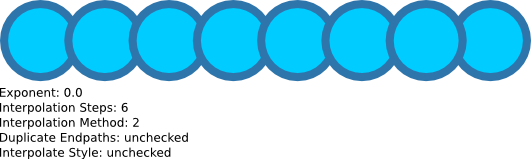
As can be seen from the above result, the space between the two circle-shaped paths has been filled with 6 (the number of interpolation steps) other circle-shaped paths. Also note that the effect groups these shapes together.
Interpolation between two different paths
When interpolation is done on two different paths, the program interpolates the shape of the path from one into the other. The result is that you get a morphing sequence between the paths, with the regularity still defined by the Interpolation Steps value.
For example, take the following two paths:

Now, select the two paths, and run the Interpolate effect. The result should be like this:
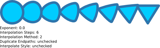
As can be seen from the above result, the space between the circle-shaped path and the triangle-shaped path has been filled with 6 paths that progress in shape from one path to the other.
When using the Interpolate effect on two different paths, the position of the starting node of each path is important. To find the starting node of a path, select the path, then choose the Node Tool so that the nodes appear and press TAB. The first node that is selected is the starting node of that path.
See the image below, which is identical to the previous example, apart from the node points being displayed. The node that is green on each path is the starting node.

The previous example (shown again below) was done with these nodes being the starting node.
Now, notice the changes in the interpolation result when the triangle path is mirrored so the starting node is in a different position:


Interpolation Method
One of the parameters of the Interpolate effect is the Interpolation Method. There are 2 interpolation methods implemented, and they differ in the way that they calculate the curves of the new shapes. The choices are either Interpolation Method 1 or 2.
In the examples above, we used Interpolation Method 2, and the result was:

Now compare this to Interpolation Method 1:

The differences in how these methods calculate the numbers is beyond the scope of this document, so simply try both, and use which ever one gives the result closest to what you intend.
Exponent
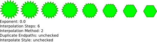
The exponent parameter controls the spacing between steps of the interpolation. An exponent of 0 makes the spacing between the copies all even.
Here is the result of another basic example with an exponent of 0.
The same example with an exponent of 1:

with an exponent of 2:

and with an exponent of -1:

When dealing with exponents in the Interpolate effect, the order that you select the objects is important. In the examples above, the star-shaped path on the left was selected first, and the hexagon-shaped path on the right was selected second.
View the result when the path on the right was selected first. The exponent in this example was set to 1:

Duplicate Endpaths
This parameter defines whether the group of paths that is generated by the effect includes a copy of the original paths that interpolate was applied on.
Interpolate Style
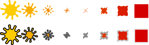
This parameter is one of the neat functions of the interpolate effect. It tells the effect to attempt to change the style of the paths at each step. So if the start and end paths are different colors, the paths that are generated will incrementally change as well.
Here is an example where the Interpolate Style function is used on the fill of a path:

Interpolate Style also affects the stroke of a path:

Of course, the path of the start point and the end point does not have to be the same either:
Using Interpolate to fake irregular-shaped gradients
It is not possible in Inkscape (yet) to create a gradient other than linear (straight line) or radial (round). However, it can be faked using the Interpolate effect and Interpolate Style. A simple example follows — draw two lines of different strokes:

And interpolate between the two lines to create your gradient:

Conclusion
As demonstrated above, the Inkscape Interpolate effect is a powerful tool. This tutorial covers the basics of this effect, but experimentation is the key to exploring interpolation further.