
Code_Aster
®
Version
5.0
Titrate:
Elements of plate DKT, DST, DKQ, DSQ, Q4g
Date:
12/01/01
Author (S):
P. MASSIN
Key:
R3.07.03-A
Page:
1/54
Manual of Reference
R3.07 booklet: Machine elements on average surface
HI-75/01/001/A
Organization (S):
EDF/MTI/MN
Manual of Reference
R3.07 booklet: Machine elements on average surface
R3.07.03 document
Elements of plate DKT, DST, DKQ, DSQ and Q4g
Summary:
These elements of plate are intended for calculations in small deformations and small displacements of structures
thin curves or plane. In fact plane elements do not take into account the geometrical curvature
structures, contrary to the elements of hull which are curved: it results from it from the parasitic bendings which
can be reduced by using more elements in order to be able to approach the geometries correctly
curves. The formulation is thus simplified by it and numbers it degrees of freedom reduced. These elements are
considered as being among most precise for the calculation of displacements and the modal analysis.

Code_Aster
®
Version
5.0
Titrate:
Elements of plate DKT, DST, DKQ, DSQ, Q4g
Date:
12/01/01
Author (S):
P. MASSIN
Key:
R3.07.03-A
Page:
2/54
Manual of Reference
R3.07 booklet: Machine elements on average surface
HI-75/01/001/A
Contents
1 Introduction ............................................................................................................................................ 4
2 Formulation ............................................................................................................................................ 5
2.1 Geometry of the elements plates [bib1] .......................................................................................... 5
2.2 Theory of the plates ........................................................................................................................ 6
2.2.1 Kinematics ........................................................................................................................... 6
2.2.2 Law of behavior ............................................................................................................. 7
2.2.3 Taking into account of transverse shearing [bib2] ................................................................. 8
2.2.3.1 The theory known as of Hencky .......................................................................................... 8
2.2.3.2 The theory known as of Reissner (DST, DSQ and Q4g) ........................................................ 9
2.2.3.3 Equivalence of the approaches Hencky-Coils-Kirchhoff and Reissner .............................. 9
2.2.3.4 Remarks ................................................................................................................ 9
3 Principle of virtual work ................................................................................................................ 10
3.1 Work of deformation ................................................................................................................... 10
3.1.1 Expression of the resulting efforts ......................................................................................... 10
3.1.2 Relation efforts resulting-deformations .............................................................................. 10
3.1.3 Energy interns elastic of plate ..................................................................................... 11
3.1.4 Remarks ........................................................................................................................... 12
3.2 Work of the forces and couples external ........................................................................................ 12
3.3 Principle of virtual work ............................................................................................................... 13
3.3.1 Kinematics of Hencky ....................................................................................................... 13
3.3.2 Kinematics of Coils-Kirchhoff ............................................................................................ 14
3.3.3 Main boundary conditions met [bib1] ........................................................... 16
4 numerical Discretization of the variational formulation resulting from the principle of virtual work ............. 17
4.1 Introduction .................................................................................................................................... 17
4.2 Discretization of the field of displacement ..................................................................................... 18
4.2.1 Approach Q4g ...................................................................................................................... 19
4.2.2 Approach DKT, DKQ, DST, DSQ ......................................................................................... 20
4.3 Discretization of the field of deformation ....................................................................................... 21
4.3.1 Discretization of the membrane field of deformation: ..................................................... 22
4.3.2 Discretization of the transverse distortion ............................................................................. 22
4.3.2.1 For the elements Q4g ............................................................................................ 22
4.3.2.2 For the elements of the type DKT, DST ....................................................................... 24
4.3.3 Discretization of the field of deformation of bending: ........................................................... 27
4.3.3.1 For the elements Q4g ............................................................................................ 27
4.3.3.2 For the elements of the type DKT, DST: .................................................................... 28
4.4 Stamp rigidity .......................................................................................................................... 30
4.4.1 Stamp elementary rigidity for the Q4g elements ........................................................ 30
4.4.2 Stamp elementary rigidity for elements DKT, DKQ .............................................. 31

Code_Aster
®
Version
5.0
Titrate:
Elements of plate DKT, DST, DKQ, DSQ, Q4g
Date:
12/01/01
Author (S):
P. MASSIN
Key:
R3.07.03-A
Page:
3/54
Manual of Reference
R3.07 booklet: Machine elements on average surface
HI-75/01/001/A
4.4.3 Stamp elementary rigidity for elements DST, DSQ .............................................. 31
4.4.4 Assembly of the elementary matrices ............................................................................... 32
4.4.4.1 Degrees of freedom ...................................................................................................... 32
4.4.4.2 Fictitious rotations ....................................................................................................... 33
4.5 Stamp of mass ........................................................................................................................... 33
4.5.1 Stamp of conventional elementary mass .............................................................................. 33
4.5.1.1 Element Q4g ............................................................................................................. 33
4.5.1.2 Elements of the type DKT, DST ..................................................................................... 34
4.5.2 Stamp of improved elementary mass ............................................................................. 34
4.5.2.1 Elements of type DKT .............................................................................................. 36
4.5.2.2 Elements of the type DST .............................................................................................. 36
4.5.2.3 Elements of the type Q4g .............................................................................................. 38
4.5.2.4 Notice ................................................................................................................. 38
4.5.3 Assembly of the elementary matrices of mass .............................................................. 38
4.5.4 Stamp of lumpée diagonal mass .................................................................................... 38
4.6 Numerical integration for elasticity ........................................................................................... 40
4.7 Numerical integration for plasticity ......................................................................................... 40
4.8 Discretization of external work ................................................................................................... 41
4.9 Taking into account of the thermal loadings ............................................................................. 43
4.9.1 Thermo elasticity of the plates .............................................................................................. 43
4.9.2 Thermomechanical chaining ................................................................................................ 45
4.9.3 Case-test ................................................................................................................................. 46
5 Establishment of the elements of plate in Code_Aster .................................................................. 47
5.1 Description: ................................................................................................................................... 47
5.2 Introduced use and developments:....................................................................................... 47
5.3 Calculation in linear elasticity:........................................................................................................... 48
5.4 Plastic design ......................................................................................................................... 49
6 Conclusion ............................................................................................................................................ 50
7 Bibliography ......................................................................................................................................... 51
Appendix 1 orthotropic Plates ................................................................................................................ 52
Appendix 2 Factors of transverse correction of shearing for orthotropic plates or stratifiées53

Code_Aster
®
Version
5.0
Titrate:
Elements of plate DKT, DST, DKQ, DSQ, Q4g
Date:
12/01/01
Author (S):
P. MASSIN
Key:
R3.07.03-A
Page:
4/54
Manual of Reference
R3.07 booklet: Machine elements on average surface
HI-75/01/001/A
1 Introduction
The elements of hulls and plates are particularly used to modelize structures
thin where the relationship between dimensions (characteristic thickness/length) is with more than 1/10.
They thus intervene particularly in fields like the civil engineering, the interns of core
ITEM, vibratory analysis ..... One limits oneself to the framework of small displacements and the small deformations.
Contrary to the elements of hull, the plane elements of plate do not make it possible to take in
hope the geometrical curvature of the structure to be represented and induce parasitic bendings. It is
thus necessary to use a great number of these elements in order to approach correctly
geometry of the structure, and this, more especially as it is curved. On the other hand, one gains in simplicity
of formulation and the number of degrees of freedom is reduced. In addition, the formulations “Discrete
Shear " (DST, DSQ and Q4g) or “Discrete Kirchhoff” (DKT and DKQ) of kinematics, with or without
transverse distortion respectively, allow good results in terms of displacements and
of modal analysis.
The way in which these elements in Code_Aster like certain receipts are established
of use are given to [§5] present note.
Code_Aster
®
Version
5.0
Titrate:
Elements of plate DKT, DST, DKQ, DSQ, Q4g
Date:
12/01/01
Author (S):
P. MASSIN
Key:
R3.07.03-A
Page:
5/54
Manual of Reference
R3.07 booklet: Machine elements on average surface
HI-75/01/001/A
2 Formulation
2.1
Geometry of the elements plates [bib1]
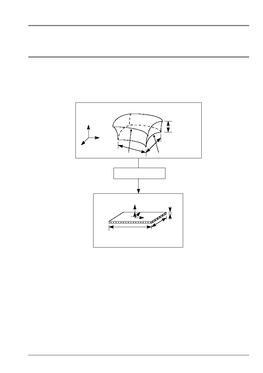
For the elements of plate one defines a surface of reference, or surfaces average, planes (plane X y
for example) and a thickness H (X, y). This thickness must be small compared to the different one
dimensions (extensions, radii of curvature) of the structure to be modelized. [Figure 2.1-a] below
illustrate our matter.
Thickness H < L, B, R
1
, R
2
Solid 3D
X
Y
Z
H
L
B
Plate
L
B
H
X
y
Z
N
R
1
R
2
Appear 2.1-a
One attaches to average surface
a reference mark orthonormé local Oxyz associated with the tangent plan with
structure different from total reference mark OXYZ. The position of the points of the plate is given by
Cartesian co-ordinates (X, y) of average surface and front elevation Z compared to this surface.

Code_Aster
®
Version
5.0
Titrate:
Elements of plate DKT, DST, DKQ, DSQ, Q4g
Date:
12/01/01
Author (S):
P. MASSIN
Key:
R3.07.03-A
Page:
6/54
Manual of Reference
R3.07 booklet: Machine elements on average surface
HI-75/01/001/A
2.2
Theory of the plates
These elements are based on the theory of the plates in small displacements and small deformations according to
which:
2.2.1 Kinematics
The cross-sections which are the sections perpendicular to average surface remain right;
material points located on a normal at not deformed average surface remain on a line
in the deformed configuration. It results from this approach that the fields of displacement vary
linearly in the thickness of the plate. If one indicates by
U v W
,
displacements of a point
Q (X, y, Z) according to X, y and Z, one has the kinematics of Hencky-Mindlin thus:
U X y Z
U X y Z
U X y Z
U X y
v X y
W X y
Z
X y
X y
U X y
v X y
W X y
Z
X y
X y
X
y
Z
y
X
X
y
(,)
(,)
(,)
(,)
(,)
(,)
(,)
(,)
(,)
(,)
(,)
(,)
(,)
=
+ -
=
+
0
0
where
U v W
,
are displacements of average surface and
X
and
y
rotations of this surface by
report/ratio with two axes X and y respectively. One prefers to introduce two rotations
X
y
y
X
X y
X y
X y
X y
(,)
(,),
(,)
(,)
=
= -
.
The three-dimensional deformations in any point, with kinematics introduced previously, are
thus given by:
xx
xx
xx
yy
yy
yy
xy
xy
xy
xy
xz
X
yz
y
E
Z
E
Z
E
Z
=
+
=
+
=
=
+
=
=
2
2
2
2
2
where
E
E
E
xx
yy
xy
,
and
are the membrane deformations of average surface,
X
y
and
deformations associated with transverse shearings, and
xx
yy
xy
,
,
deformations of bending
average surface, which is written:

Code_Aster
®
Version
5.0
Titrate:
Elements of plate DKT, DST, DKQ, DSQ, Q4g
Date:
12/01/01
Author (S):
P. MASSIN
Key:
R3.07.03-A
Page:
7/54
Manual of Reference
R3.07 booklet: Machine elements on average surface
HI-75/01/001/A
E
U
X
E
v
y
E
v
X
U
y
X
y
y
X
W
X
W
y
xx
yy
xy
xx
X
yy
y
xy
X
y
X
X
y
y
=
=
=
+
=
=
=
+
=
+
=
+
2
2
Note:
In the theories of plate the introduction of
X
and
y
allows to symmetrize the formulations of
deformations and will see we it thereafter the equilibrium equations. In the theories of hull
one uses rather
X
and
y
and associated couples
M
X
and
M
y
compared to X and Y.
2.2.2 Law of behavior
The behavior of the plates is a behavior 3D in “plane stresses”. The stress
transversal
zz
bus is null regarded as negligible compared to the other components of
tensor of the stresses (assumption of the plane stresses). The most general law of behavior
is written then as follows:
xx
yy
xy
xz
yz
xx
yy
xy
X
y
Z
=
=
+
+
C
It
C
C
(,)
with
E
=
=
E
E
E
xx
yy
xy
xx
yy
xy
X
y
2
0
0
2
0
0
0
0
0
,
.
and
=
where
()
C
,
is the matrix of local tangent rigidity combining forced plane and distortion
transverse and
represent the whole of the internal variables when the behavior is nonlinear.

Code_Aster
®
Version
5.0
Titrate:
Elements of plate DKT, DST, DKQ, DSQ, Q4g
Date:
12/01/01
Author (S):
P. MASSIN
Key:
R3.07.03-A
Page:
8/54
Manual of Reference
R3.07 booklet: Machine elements on average surface
HI-75/01/001/A
For behaviors where the distortions are uncoupled from the deformations of membrane and from
bending,
()
C
,
puts itself in the form:
C
H
H
=
0
0
where
()
H
,
is a matrix 3x3 and
()
H
,
a matrix 2x2. One will remain within the framework of this
assumption.
For an isotropic homogeneous linear behavior elastic, one has as follows:
C
= -
-
-
-
E
v
v
v
v
K
v
K
v
1
1
0
0
0
1
0
0
0
0 0 1 2
0
0
0 0
0
1
2
0
0 0
0
0
1
2
2
(
)
(
)
where
K
is factor of transverse correction of shearing whose significance is given to
following paragraph.
Note:
One does not describe the variation thickness nor that of the transverse deformation
zz
that one
can however calculate by using the preceding assumption of plane stresses. In addition
no restriction is made on the type of behavior that one can represent.
2.2.3 Taking into account of transverse shearing [bib2]
The taking into account of transverse shearing depends on factors of correction determined a priori by
energy equivalences with models 3D, so that rigidity in shearing
transverse of the model of plate is nearest possible to that defined by the theory of elasticity
three-dimensional. Two theories including the deformation due to the shearing action exist and are
presented in [bib2].
2.2.3.1 The theory known as of Hencky
This theory as that of Coils-Kirchhoff which results from this immediately rests on
kinematics presented to [§2.2.1]. The relation of behavior is usual and the factor of
correction of shearing is worth k=1.

Code_Aster
®
Version
5.0
Titrate:
Elements of plate DKT, DST, DKQ, DSQ, Q4g
Date:
12/01/01
Author (S):
P. MASSIN
Key:
R3.07.03-A
Page:
9/54
Manual of Reference
R3.07 booklet: Machine elements on average surface
HI-75/01/001/A
Note:
The model of Coils-Kirchhoff (DKT and DKQ): When one does not take into account the distortions
transverses
X
and
y
in the theory of Hencky, the model obtained is that of Coils-Kirchhoff.
Two rotations of average surface are then related to displacements of surface
average by the following relation:
X
y
W
X
W
y
= -
= -
2.2.3.2 The theory known as of Reissner (DST, DSQ and Q4g)
The second theory, known as of Reissner, is developed starting from the stresses. Variation of
membrane stresses (
xx
,
yy
and
xy
) is supposed to be linear in the thickness like in the case of
the theory of Hencky where that results from the linearity of the variation of the deformations of membrane with
the thickness. However, whereas one supposes, in the theory of Hencky, the constant distortion in
the shear thickness and thus stresses, which violates the boundary conditions
xz
=
yz
=0 on
faces higher and lower of the plate because of law of behavior stated than the §2.2.2., one
use within the framework of the theory of Reissner the equilibrium equations to deduce the variation from it from
shear stresses in the thickness of the plate, by observing the conditions in particular
of balance on the faces higher and lower of plate. Energy interns model afterwards obtained
resolution of the equilibrium equations in 3D, for bending only, with the variation of
plane stresses according to Z, reveals, for an elastic material, a relation between the efforts
resulting and rotations and the arrow averages. It is in this relation that the factor appears of
correction of shearing of k=5/6 instead of 1 in the relation which binds the sharp effort to the distortion
for a homogeneous and isotropic plate. Determination of the factors of correction of shearing
for orthotropic plates or laminated plates is left in appendix.
2.2.3.3 Equivalence of the approaches Hencky-Coils-Kirchhoff and Reissner
If one assimilates the slopes of average surface
X
,
y
with the averages of the slopes in the thickness of
the plate and the arrow W with the average arrow, the only difference between the theory of Hencky and that of
Reissner is the coefficient of transverse correction of shearing of 5/6 instead of 1. This difference
is due to the fact that the starting assumptions are of different nature and especially that the variables
chosen are not the same ones. Indeed, the arrow on average surface is not equal to
average of the arrows on the thickness of the plate. It is thus normal that relations of
behavior which utilizes different variables are not identical.
The fact of having to solve on the level finite elements of the problems in displacements rather than of
problems in stresses by interpolation of displacements leads us to use the approach
equivalent in displacements of the problem of Reissner formulated in stresses.
2.2.3.4 Remarks
Because of preceding equivalence one presents here only the model in displacement for all them
elements. In the facts elements DKT and DKQ are based on the theory of Hencky-Coils-Kirchhoff and
the elements DST, DSQ and Q4
are based on the theory of Reissner.
The determination of the factors of correction rests within the framework of another theory, that of Mindlin,
on equivalences of Eigen frequency associated the mode of vibration by transverse shearing.
K= then is obtained
2
/12, value very close to 5/6 for the DST elements, DSQ and Q4
in the case
isotropic.

Code_Aster
®
Version
5.0
Titrate:
Elements of plate DKT, DST, DKQ, DSQ, Q4g
Date:
12/01/01
Author (S):
P. MASSIN
Key:
R3.07.03-A
Page:
10/54
Manual of Reference
R3.07 booklet: Machine elements on average surface
HI-75/01/001/A
Within the framework of plasticity the problem of the choice of the coefficient of correction of shearing
transverse arises because the equivalent approach in displacements of the problem of Reissner formulated in
stresses utilizes the non-linearity of the behavior. One cannot thus deduce some, like
it is the case for elastic materials a value of the coefficient of correction of shearing
transverse. Plasticity is thus not developed for these elements.
3
Principle of virtual work
3.1
Work of deformation
The general expression of the work of deformation 3D for a plate is worth:
W
FD
xx xx
yy yy
H
H
xy xy
X xz
y yz
S
def
=
+
+
+
+
-
(
)
/
/
2
2
where S is average surface and the position in the thickness of the plate varies between H/2 and +h/2.
3.1.1 Expression of the resulting efforts
By adopting the kinematics of [§2.2.1], one identifies the work of the interior efforts:
W
E NR
E NR
E NR
M
M
M
T
T dS
xx
S
xx
yy
yy
xy
xy
xx
xx
yy
yy
xy
xy
X X
y y
def
=
+
+
+
+
+
+
+
(
)
2
2
where:
NR
=
=
-
+
NR
NR
NR
dz
xx
yy
xy
xx
yy
xy
H
H
/
/
2
2
;
M
=
=
-
+
M
M
M
zdz
xx
yy
xy
xx
yy
xy
H
H
/
/
2
2
;
T
= =
-
+
T
T
dz
X
y
xz
yz
H
H
/
/
2
2
.
NR
NR
NR
xx
yy
xy
,
,
are the efforts resulting from membrane (in NR/m);
M
M
M
xx
yy
xy
,
,
are the efforts resulting from bending or moments (in NR);
T T
X
y
,
,
are the efforts resulting from shearing or sharp efforts (in NR/m);
3.1.2 Relation efforts resulting-deformations
The expression of the work of deformation is also written:
W
FD
Z
Z
Z
FD
H
H
S
H
H
S
def
=
=
+
+
+
+
-
-
[
(,)]
[
]
/
/
/
/
C
eCe
EC.
It
C
C
2
2
2
2
2
where
()
C
,
is the local matrix of behavior.

Code_Aster
®
Version
5.0
Titrate:
Elements of plate DKT, DST, DKQ, DSQ, Q4g
Date:
12/01/01
Author (S):
P. MASSIN
Key:
R3.07.03-A
Page:
11/54
Manual of Reference
R3.07 booklet: Machine elements on average surface
HI-75/01/001/A
By using the expression obtained for
W
def
in the preceding paragraph one finds the relation following
between the resulting efforts and the deformations:
NR H E H
MR. H
E H
T H
m
MF
MF
F
ct
=
+
=
+
=
with
H
H
H
H
H
H
m
MF
F
=
=
=
-
+
-
+
-
+
dz
zdz
Z dz
H
H
H
H
H
H
,
/
/
/
/
/
/
2
2
2
2
2
2
2
,
and:
H
ct
=
G
G
11
22
0
0
and:
E
=
=
=
E
E
E
xx
yy
xy
xx
yy
xy
X
y
2
2
,
,
Matrices
H
H
H
m
F
ct
,
and
are the matrices of rigidity out of membrane, bending and shearing
transverse, respectively. The matrix
H
MF
is a matrix of rigidity of coupling between
membrane and the bending.
For an isotropic homogeneous elastic behavior of plate these matrices have as an expression:
H
H
H
m
F
ct
= -
-
=
-
-
=
+
Eh
v
v
v
v
Eh
v
v
v
v
kEh
v
1
1
0
1
0
0 0 1 2
12 1
1
0
1
0
0 0 1 2
2 1
1 0
0 1
2
3
2
,
(
)
,
(
)
, and
H
MF
= 0 bus there is material symmetry compared to the z=0 plan.
For an orthotropic material, the behavior is given in appendix.
3.1.3 Energy interns elastic of plate
Taking into account the preceding remarks, energy interns elastic plate is expressed more
usually for this kind of geometry in the following way:
int
=
+
+
+
+
1
2 [(
)
(
)
]
E H E H
H
E H
H
m
MF
MF
F
ct
S
dS
.

Code_Aster
®
Version
5.0
Titrate:
Elements of plate DKT, DST, DKQ, DSQ, Q4g
Date:
12/01/01
Author (S):
P. MASSIN
Key:
R3.07.03-A
Page:
12/54
Manual of Reference
R3.07 booklet: Machine elements on average surface
HI-75/01/001/A
3.1.4 Remarks
Relations flexible
H
H H
H
H
H
m
F
MF
ct
,
,
with
and
with
are valid whatever the law of
elastic behavior, with anelastic deformations (thermoelasticity, plasticity,….).
For a plate made up of NR orthotropic layers in elasticity, matrices
H
H H
H
m
F
MF
ct
,
,
and
are written:
H
H H
H H
H H
H
m
I
MF
I
F
I
ct
=
=
=
-
=
=
=
+
=
=
H
H
Z
Z
H
I
I
NR
I I
I
NR
I
I
I
I
I
NR
I
NR
1
1
1
3
3
1
1
1
3
,
,
(
)
,
where:
(
)
H
Z
Z
Z
Z
I
I
I
I
I
I
=
-
=
+
+
+
1
1
1
2
,
and
H H
I
I
,
the matrices represent
H
H
and
for the layer
I.
The homogenization for multi-layer hulls can lead to matrices of rigidity of
membrane and of bending nonproportional of the type:
H
H
H
m
F
ct
=
=
=
C
C
C
C
C
D
D
D
D
D
G
G
1111
1122
1122
2222
1212
1111
1122
1122
2222
1212
11
22
0
0
0
0
0
0
0
0
0
0
,
,
for which one cannot find equivalent values of the Young modulus and thickness
allowing to find the conventional expressions of rigidity, cf [bib7].
3.2
Work of the forces and couples external
The work of the forces and couples being exerted on the plate is expressed in the following way:
W
FD
dS
dzds
H
H
S
S
H
H
C
ext.
=
+
+
-
+
-
+
F U
F U
F U
v
S
C
.
.
.
/
/
/
/
2
2
2
2
where
F F F
v
S
C
,
are the voluminal, surface efforts and of contour being exerted on the plate,
respectively. C is the part of the contour of the plate on which efforts of contour
F
C
are
applied. With the kinematics of [§2.2.1], one determines as follows:
W
F U
F v
F W.C.
C
dS
U
v
W
ds
F U
F v
F W.C.
C
dS
U
v
W
ds
X
y
Z
X X
y y
S
X
y
Z
X X
y y
C
X
y
Z
y X
X y
S
X
y
Z
y X
X y
C
ext.
=
+
+
+
+
+
+
+
+
+
=
+
+
+
-
+
+
+
+
-
(
)
(
)
(
)
(
)

Code_Aster
®
Version
5.0
Titrate:
Elements of plate DKT, DST, DKQ, DSQ, Q4g
Date:
12/01/01
Author (S):
P. MASSIN
Key:
R3.07.03-A
Page:
13/54
Manual of Reference
R3.07 booklet: Machine elements on average surface
HI-75/01/001/A
·
where are present on the plate:
F
F
F
X
y
Z
,
,
: surface forces acting according to
X y
,
and
Z
F
dz
I
H
H
=
+
-
+
F E
F E
v
I
S
I
.
.
/
/
2
2
where
E
X
and
E
y
are the basic vectors of the tangent plan and
E
Z
their
normal vector.
C C
X
y
,
: surface couples acting around the axes
X
and
y
.
C
Z
dz
H
I
H
H
=
+ ±
-
+
(
).
(
).
/
/
E
F
E
E
F E
Z
v
I
Z
S
I
2
2
2
where
E E E
X
y
Z
,
,
are the basic vectors
previously definite.
·
and where are present on the contour of the plate:
X
y
Z
,
: linear forces acting according to
X y
,
and
Z
I
H
H
dz
=
-
+
F E
C
I
.
/
/
2
2
where E
X
, E
y
, E
Z
are the basic vectors previously definite.
X
y
,
: linear couples around the axes
X
and
y
.
I
H
H
Z
dz
=
-
+
(
).
/
/
E
F E
Z
C
I
2
2
where
E E E
X
y
Z
,
,
are the basic vectors previously definite.
Note:
The moments compared to Z are null.
3.3
Principle of virtual work
It is written in the following way:
W
W
ext.
def
=
for all virtual displacements and rotations
acceptable.
3.3.1 Kinematics of Hencky
With this kinematics, it results after integration by parts of work of deformation them
equilibrium equations static of the following plates:
·
For the efforts:
NR
NR
F
NR
NR
F
T
T
F
xx X
xy y
X
yy y
xy X
y
X X
y y
Z
,
,
,
,
,
,
,
,
.
+
+
=
+
+
=
+
+
=
0
0
0
·
For the couples:
M
M
T
C
M
M
T
C
xx X
xy y
X
y
yy y
xy X
y
X
,
,
,
,
,
.
+
-
+
=
+
-
-
=
0
0
Code_Aster
®
Version
5.0
Titrate:
Elements of plate DKT, DST, DKQ, DSQ, Q4g
Date:
12/01/01
Author (S):
P. MASSIN
Key:
R3.07.03-A
Page:
14/54
Manual of Reference
R3.07 booklet: Machine elements on average surface
HI-75/01/001/A
as well as the boundary conditions following on contour C of S:
NR N
NR N
NR N
NR N
T N
T N
M N
M N
M N
M N
xx X
xy y
X
yy y
xy X
y
X X
y y
Z
xx X
xy y
y
yy y
xy X
X
+
=
+
=
+
=
+
=
+
= -
,
,
,
,
.
or
U U
v v
W W
X
y
y
X
=
=
=
=
= -
,
,
,
,
.
where
N
X
and
N
y
are the cosine Directors of the normal with C directed towards the outside of the plate.
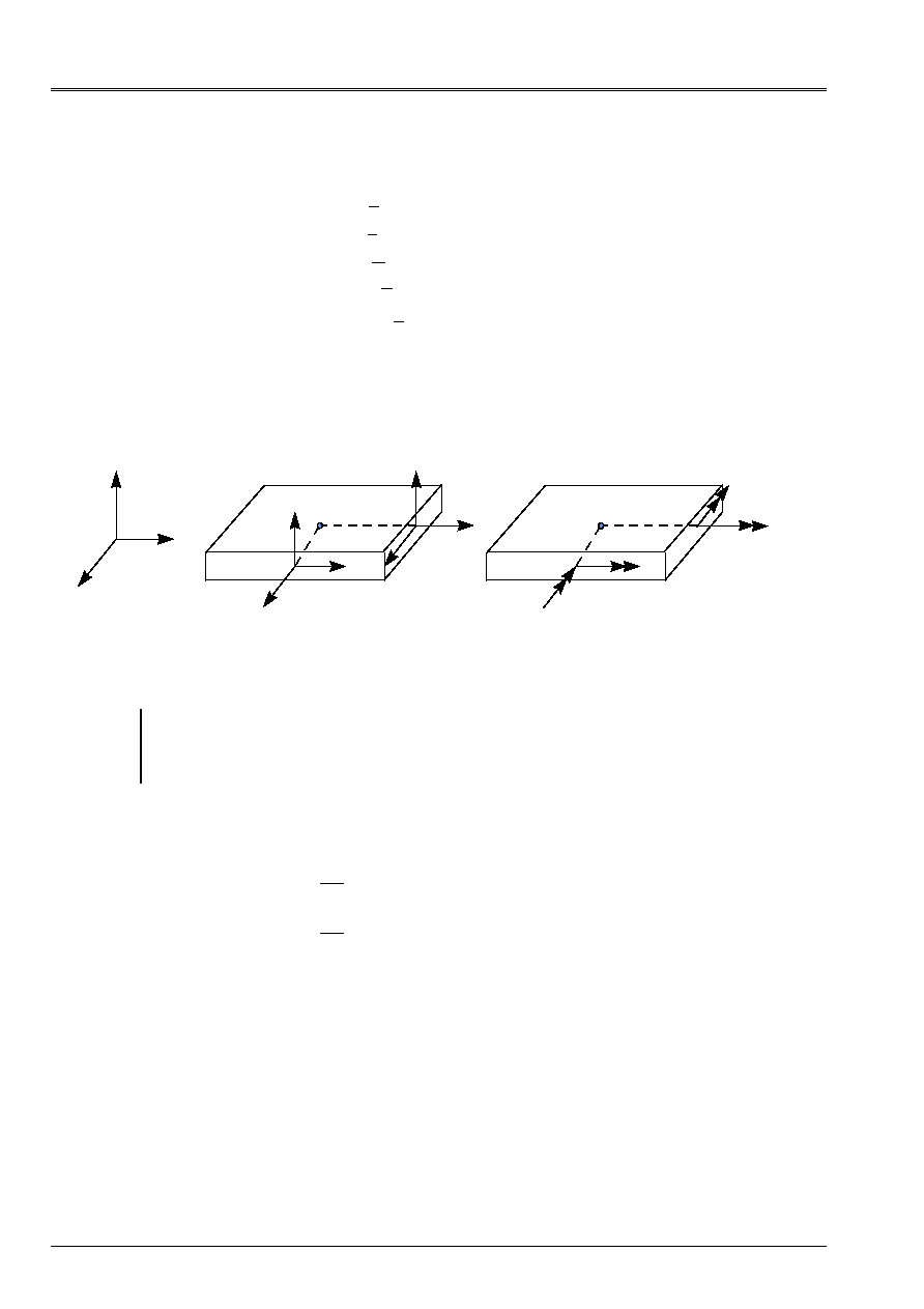
The physical interpretation of these efforts (NR, T and M) starting from the preceding equations is given
below:
y
Z
X
NR
xx
NR
xy
T
X
P
NR
yy
T
y
NR
yx
M
xy
M
xx
P
M
yx
M
yy
Appear 3.3.1-a: Efforts resulting for an element from plate
Note:
NR
NR
xx
yy
,
represent the tensile loads and
NR
xy
plane shearing.
M
xx
and
M
yy
the couples of bending represent and
M
xy
the torque.
T
X
and
T
y
, are the efforts of
transverse shearing.
3.3.2 Kinematics of Coils-Kirchhoff
One recalls that within the framework of this kinematics, one with the following relation binding the derivative of
arrow with rotations:
X
y
W
X
W
y
= -
= -
. After a double integration by parts of the work of deformation,
one obtains the following equilibrium equations static:
·
For the efforts of membrane:
NR
NR
F
NR
NR
F
xx X
xy y
X
yy y
xy X
y
,
,
,
,
,
,
+
+
=
+
+
=
0
0
·
For the transverse shearing and bending loads:
M
M
M
F
C
C
M
M
T
C
M
M
T
C
xx xx
xy xy
yy yy
Z
y X
X y
xx X
xy y
X
y
yy y
xy X
y
X
,
,
,
,
,
,
,
,
,
,
,
.
+
+
+
+
-
=
+
-
+
=
+
-
-
=
2
0
0
0
Code_Aster
®
Version
5.0
Titrate:
Elements of plate DKT, DST, DKQ, DSQ, Q4g
Date:
12/01/01
Author (S):
P. MASSIN
Key:
R3.07.03-A
Page:
15/54
Manual of Reference
R3.07 booklet: Machine elements on average surface
HI-75/01/001/A
as well as the boundary conditions on contour C and with the angular points O of contour C of S:
NR N
NR N
NR N
NR N
T
M
M
M
O
M
O
O
O
xx X
xy y
X
yy y
xy X
y
N
NS S
Z
N S
N
S
NS
NS
N
N
+
=
+
=
+
=
-
=
+ -
- = -
+ -
-
,
,
,
,
(
)
(
)
[
(
)
(
)].
,
,
or
U U
v v
W W
W
N
N
S
=
=
=
= -
=
,
,
,
.
,
with
T
T N
T N
M
M N
M N N
M N
M
M N N
M
N
N
M N N
N
X X
y y
N
xx X
xy X y
yy y
NS
xx X y
xy
X
y
yy X y
=
+
=
+
+
= -
+
-
+
,
,
(
)
.
2
2
2
2
2
.
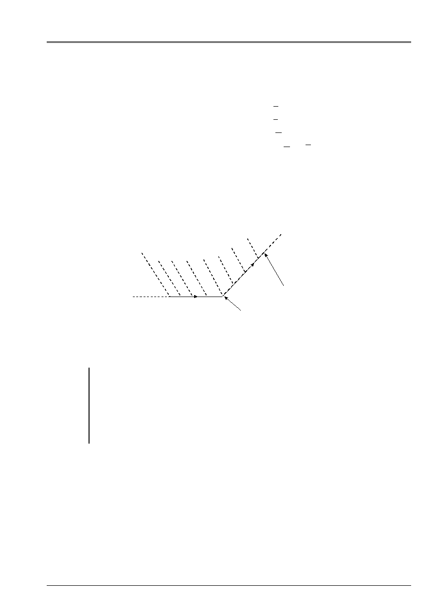
Surface average S
Contour
Discontinuity
S
S
M
NS
(-)
M
NS
(+)
Appear 3.3.2-a: Boundary condition with angular points for an element of plate
Note:
The kinematics of Coils-Kirchhoff implies that on the contour of the plate the shearing force
transverse is related to the torque. It is noted that the command of the equilibrium equations of
bending is higher than with the kinematics of Hencky. Thus, to choose the kinematics of
Coil-Kirchhoff come down to increase the degree of the functions of interpolation because a regularity is needed
larger for the terms of arrow compared to the terms of membrane because of presence
from derived seconds of the arrow in the expression of the work of the deformations. No element
of plate of Code_Aster does not use this kinematics. One can thus have differences between
results obtained with the elements of Code_Aster and the analytical results obtained in
using the kinematics of Coils-Kirchhoff for structures with angular contours.
Code_Aster
®
Version
5.0
Titrate:
Elements of plate DKT, DST, DKQ, DSQ, Q4g
Date:
12/01/01
Author (S):
P. MASSIN
Key:
R3.07.03-A
Page:
16/54
Manual of Reference
R3.07 booklet: Machine elements on average surface
HI-75/01/001/A
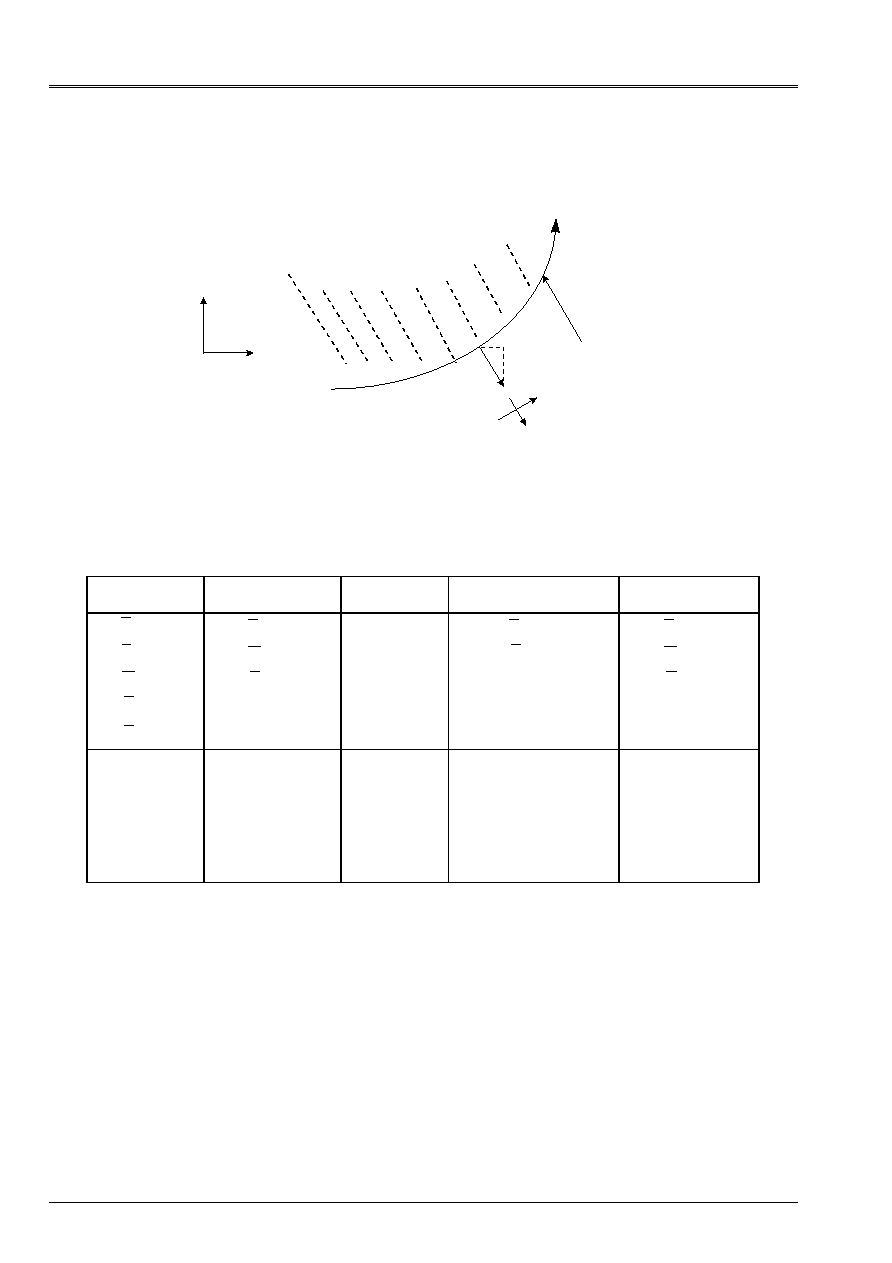
3.3.3 Main boundary conditions met [bib1]
Surface average S
Contour
S
N
X
y
N
X
N
y
S
,
S
N
,
N
Appear 3.3.3-a: Boundary condition for an element of plate
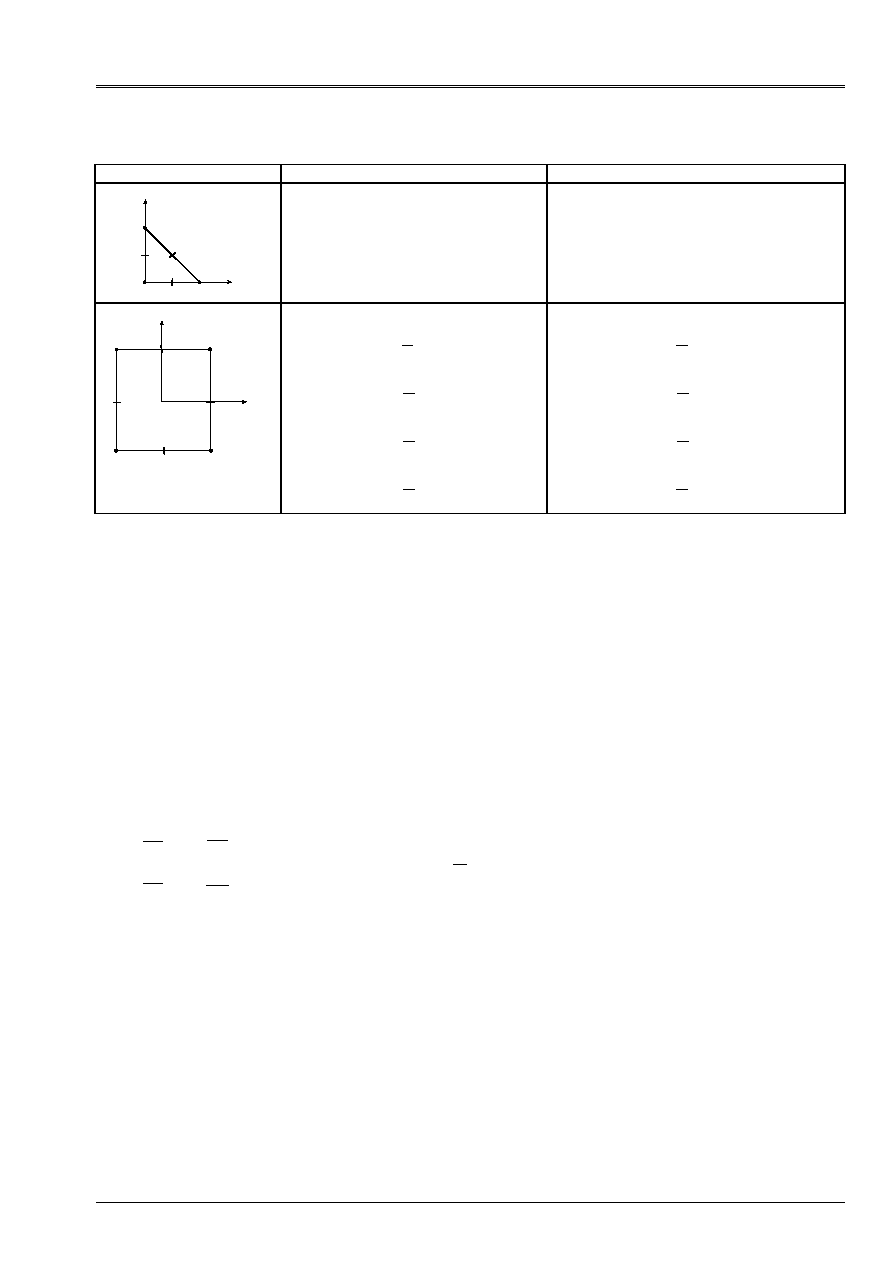
The boundary conditions frequently met are gathered in the table which follows. They
are given for the kinematics of Hencky in the reference mark defined by S and the normal external with
plate:
Embedding
Simple support
Free edge
Symmetry compared to
an axis S
Antisymetry by
report/ratio with an axis S
U
v
W
S
N
=
=
=
=
=
0
0
0
0
0
,
,
,
,
.
U
W
N
N
=
=
=
0
0
0
,
,
.
U
N
S
=
=
0
0
,
.
U
W
S
N
=
=
=
0
0
0
,
,
.
S
S
=
=
0
0
,
.
S
N
Z
S
N
=
=
=
=
=
0
0
0
0
0
,
,
,
,
S
Z
N
=
=
=
0
0
0
,
,
.
N
S
=
=
0
0
,
.
with:
U
one
vn
U
one
vn
N
N
N
N
N
N N
N
N N
N
N
N N
N
N N
N
N N
N
N
N N
N
X
y
S
y
X
N
X X
y y
S
X y
y X
N
X X
xy X y
y y
S
X X y
xy
X
y
y X y
N
X X
xy X y
y y
S
X X y
xy
X
y
y X y
=
+
= -
+
=
+
= -
+
=
+
+
= -
+
-
+
=
+
+
= -
+
-
+
;
,
;
,
,
(
)
,
,
(
)
.
2
2
2
2
2
2
2
2
2
2
Code_Aster
®
Version
5.0
Titrate:
Elements of plate DKT, DST, DKQ, DSQ, Q4g
Date:
12/01/01
Author (S):
P. MASSIN
Key:
R3.07.03-A
Page:
17/54
Manual of Reference
R3.07 booklet: Machine elements on average surface
HI-75/01/001/A
Note: one has
S
N
N
S
= -
=
,
.
.
4
Numerical discretization of the variational formulation
exit of the principle of virtual work
4.1 Introduction
By exploiting the law of behavior, the virtual work of the interior efforts is written (with
H
MF
=0
until [§4.4], which does not remove anything with the general information following results, but allows to reduce them
notations):
W
dS
S
int
=
+
+
(
)
eH E
H
H
m
F
ct
with:
E
=
+
=
+
=
+
+
U
v
U
v
W
W
X
y
y
X
X X
y y
X y
y X
X
X
y
y
,
,
,
,
,
,
,
,
,
,
,
,
.
It results from it that the elements of plate are elements with five degrees of freedom per node. These
degrees of freedom are displacements in the plan of the element
U
and
v
, except plan
W
and both
rotations
X
and
y
.
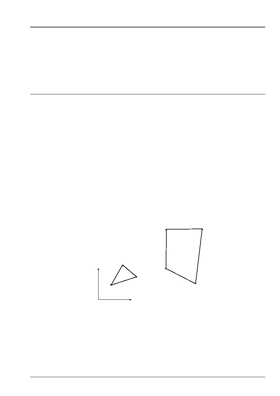
The elements DKT and DST are triangular isoparametric elements. Elements DKQ, DSQ
and Q4
are quadrilateral isoparametric elements. They are represented below:
y
X
1
1
1
1
2
2
2
2
3
3
3
3
4
4
4
4
2
2
2
2
1
1
1
1
3
3
3
3
Appear 4.1-a: real Elements
Code_Aster
®
Version
5.0
Titrate:
Elements of plate DKT, DST, DKQ, DSQ, Q4g
Date:
12/01/01
Author (S):
P. MASSIN
Key:
R3.07.03-A
Page:
18/54
Manual of Reference
R3.07 booklet: Machine elements on average surface
HI-75/01/001/A
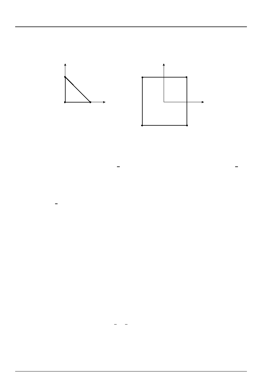
The elements of reference are presented below:
(0,0)
(1,0)
(0,1)
(- 1,1)
(1,1)
(1, - 1)
(- 1, - 1)
1
1
1
1
2
2
2
2
3
3
3
3
4
4
4
4
1
1
1
1
2
2
2
2
3
3
3
3
Appear 4.1-b: Elements of reference triangle and quadrangle
One defines the reduced reference mark of the element as the reference mark (
,
) of the element of reference. The local reference mark
element, in its plan (X, y) is defined by the user. The X1 direction of this local reference mark is
projection of a direction of reference D in the field of the element. This direction of reference D is
chosen by the user who defines it by two nautical angles in the total reference mark. The normal NR with
plan of the element (12
13 for a triangle numbered 123 and 12
14 for a numbered quadrangle
1234) fix the second direction. The vector product of the two vectors previously definite
Y1=N
X1 makes it possible to define the local trihedron in which will be expressed the generalized efforts
representing the state of stresses. The user will have to take care that the selected reference axis
do not find parallel with the normal of certain elements of plate. By defect, direction of
reference D is axis X of the total reference mark of definition of the mesh.
The essential difference between elements DKT, DKQ on the one hand and DST, DSQ, Q4
in addition comes
owing to the fact that for the first the transverse distortion is null is still
= 0. The difference between Q4
and elements DST and DSQ comes from a choice different of interpolation for the representation of
transverse shearing.
4.2
Discretization of the field of displacement
If one discretizes the fields of displacement in the usual way for elements
isoparametric i.e.:
U
NR U v
NR v W
NR W
NR
NR
I
I
NR
I
I
I
NR
I
I
I
NR
I
X
I
I
NR
xi
y
I
I
NR
yi
=
=
=
=
=
=
=
=
=
=
1
1
1
1
1
,
,
,
,
,
and that one introduces this discretization into the variational formulation of [§4.1] it a blocking results from it
in transverse shearing analyzed in [bib1] which returns the solution in bending controlled by the effects of
transverse shearing, and not by the bending, when the thickness of the plate becomes small by report/ratio
with its characteristic dimension.
To cure this disadvantage the variational form presented in introduction is slightly
modified so that:
W
dS
dS
S
S
int
=
+
+
=
+
+
-
(
)
(
)
eH E
H
H
eH E
H
TH T
m
F
ct
m
F
ct1

Code_Aster
®
Version
5.0
Titrate:
Elements of plate DKT, DST, DKQ, DSQ, Q4g
Date:
12/01/01
Author (S):
P. MASSIN
Key:
R3.07.03-A
Page:
19/54
Manual of Reference
R3.07 booklet: Machine elements on average surface
HI-75/01/001/A
where
are deformations of substitution checking
=
in a weak way (integral on the sides of
the element) and such as
T H
ct
=
. One checks thus that on the sides ij of the element
(
)
S
S
I
J
ds
-
=
0
with
S
S
S
W
=
+
,
.
Two approaches are then possible; in the first, that of the Q4 element
, one uses
bilinear discretization of the fields of displacement and the fact that
is constant on the sides of
the element. The relations on the sides ij then make it possible to express the values of
on the sides in
function of the degrees of freedom of bending. In the second approach, which is that of the elements of the type
DKT and DST, one uses the weak formulation of the preceding paragraph which makes it possible to bind the bending to
shearing forces to deduce the interpolation from it from the terms of bending.
4.2.1 Approach
Q4g
It rests on the linear discretization of the fields of displacement presented above:
U
NR U v
NR v W
NR W
NR
NR
I
I
NR
I
I
I
NR
I
I
I
NR
I
X
I
I
NR
xi
y
I
I
NR
yi
=
=
=
=
=
=
=
=
=
=
1
1
1
1
1
,
,
,
,
,
where the functions NR
I
are given below.
NR
I
(i=1, N)
4
3
2
1
Q4
i=1 with 4
NR
NR
NR
NR
1
2
3
4
1
4 1
1
1
4 1
1
1
4 1
1
1
4 1
1
(,)
(
) (
)
(,)
(
) (
)
(,)
(
) (
)
(,)
(
) (
)
=
-
-
=
+
-
=
+
+
=
-
+
Functions NR
I
for the Q4 elements
Note:
One notes too
NR
I
I
I
(,)
(
) (
)
=
+
+
1
4 1
1
with
(,) (,)
1
2
3
4
111 1
= -
-
and
(,
,
,
) (,)
1
2
3
4
1 111
= - -
.
Code_Aster
®
Version
5.0
Titrate:
Elements of plate DKT, DST, DKQ, DSQ, Q4g
Date:
12/01/01
Author (S):
P. MASSIN
Key:
R3.07.03-A
Page:
20/54
Manual of Reference
R3.07 booklet: Machine elements on average surface
HI-75/01/001/A
4.2.2 Approach DKT, DKQ, DST, DSQ
Like
T
M
M
T
M
M
X
xx X
xy y
y
yy y
xy X
=
+
=
+
,
,
,
,
and
and
MR. H
F
=
one deduces from it that
is defined
according to the derived seconds of
X
and
y
via two equilibrium equations internal
and of the law of behavior in bending. Discretization retained for
X
and
y
, such as
S
is
quadratic on the sides and
N
linear, then utilizes of the quadratic functions of forms
incomplete in the form:
X
K
K
NR
xk
xk
K
K NR
NR
y
K
K
NR
yk
yk K
K NR
NR
NR
P
NR
P
=
+
=
+
=
= +
=
= +
1
1
2
1
1
2
,
with
P
PC
P
P S
xk
K K
yk
K K
=
=
and
where
C
K
and
S
K
are the cosine and directing sines on the side ij to which the node belongs
K
defined by:
(
)
C
X
L
X
X
L
S
y
L
y
y
L
L
X
y
K
ji
K
J
I
K
K
ij
K
J
I
K
K
ji
ji
=
=
-
=
=
-
=
+
/
(
)/
;
/
(
)/
;
.
/
2
2 1 2
Note:
To introduce the preceding discretization amounts adding like degrees of freedom to the element of
rotations
K
in the middle of the sides K of the element. Indeed, rotations
S
and
N
such as:
S
N
X
y
C
S
S
C
=
-
are quadratic for
S
and linear for
N
with:
S
if
sj
K
N
nor
nj
S
S
S
S
S
S
= -
+
+ -
= -
+
(
)
(
)
;
(
)
1
4 1
1
where
0
1
=
S
S L
K
/
.
One observes thus that:
sk
S
if
sj
K
S
=
=
=
+
+
(
)
(
)
1
2
1
2
.
It is the relation
(
)
S
S
I
J
ds
-
=
0
with
S
S
S
W
=
+
,
who will allow to eliminate the degrees from
freedom additional and to express them according to displacements and of nodal rotations.
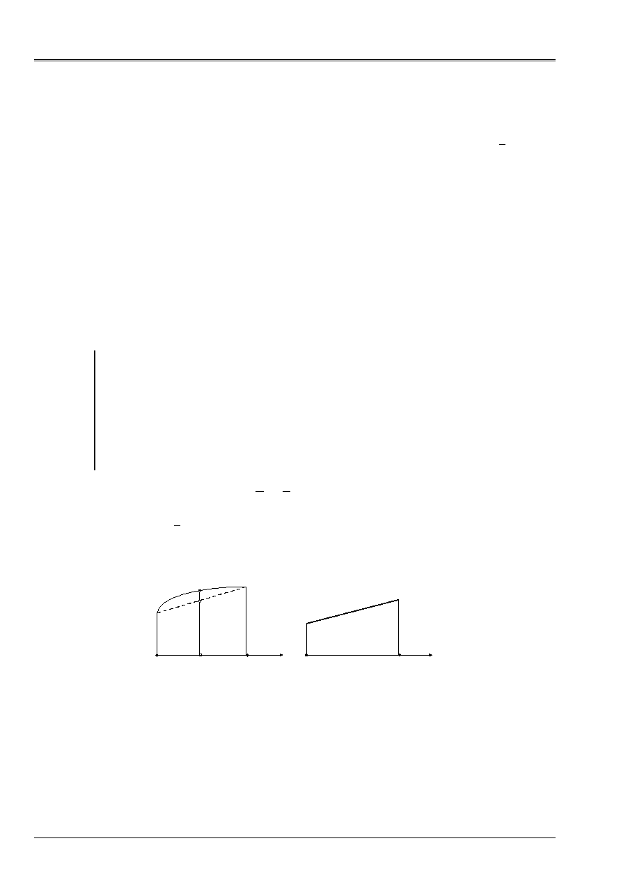
Variation of
S
Variation of
N
I
I
J
J
S
S
nor
nj
if
sj
sk
K
1/2 (
if
+
sj
)
K
Appear 4.2.2-a: Variations of
S
and
N
Code_Aster
®
Version
5.0
Titrate:
Elements of plate DKT, DST, DKQ, DSQ, Q4g
Date:
12/01/01
Author (S):
P. MASSIN
Key:
R3.07.03-A
Page:
21/54
Manual of Reference
R3.07 booklet: Machine elements on average surface
HI-75/01/001/A
NR
I
(i=1, N)
P
I
(i=n+1,2n)
1
2
3
4
5
6
DKT, DST
i=1 with 3
NR
NR
NR
1
2
3
1
(,)
(,)
(,)
= = - -
=
=
i=4 with 6
P
P
P
4
5
6
4
4
4
(,)
(,)
(,)
=
=
=
4
3
2
1
5
6
7
8
DKQ, DSQ
i=1 with 4
NR
NR
NR
NR
1
2
3
4
1
4 1
1
1
4 1
1
1
4 1
1
1
4 1
1
(,)
(
) (
)
(,)
(
) (
)
(,)
(
) (
)
(,)
(
) (
)
=
-
-
=
+
-
=
+
+
=
-
+
i=5 with 8
P
P
P
P
5
2
6
2
7
2
8
2
1
2 1
1
1
2 1
1
1
2 1
1
1
2 1
1
(,)
(
) (
)
(,)
(
) (
)
(,)
(
) (
)
(,)
(
) (
)
=
-
-
=
-
+
=
-
+
=
-
+
Functions NR
I
and P
I
for elements DKT, DST, DKQ, DSQ
4.3
Discretization of the field of deformation
The matrix jacobienne
J (,)
is:
J
=
=
=
=
=
=
=
X
y
X
y
NR X
NR y
NR X
NR y
J
J
J
J
I
I
I
NR
I
I
I
NR
I
I
I
NR
I
I
I
NR
,
,
,
,
,
,
,
,
1
1
1
1
11
12
21
22
.
Moreover:
X
y
J
J
J
J
J
J
J
J
J
J
J J
J J
=
=
=
=
-
-
=
=
-
J
J
J
J
-
with
or
11
12
21
22
1
22
12
21
11
11 22
12 21
1
det
It is reminded the meeting that the field of displacement is discretized by:
()
U
v
NR
U
v
K
K
K
K
NR
=
=
,
1
and
W
NR
W
P
P
X
y
K
K
xk
yk
K
NR
xk
yk
K NR
NR
K
=
+
=
= +
(,)
[
(,)
(,)
]
1
1
2
0
, the term enters
hooks being present for the elements of the type DKT, DST, but not for the Q4 elements
.

Code_Aster
®
Version
5.0
Titrate:
Elements of plate DKT, DST, DKQ, DSQ, Q4g
Date:
12/01/01
Author (S):
P. MASSIN
Key:
R3.07.03-A
Page:
22/54
Manual of Reference
R3.07 booklet: Machine elements on average surface
HI-75/01/001/A
4.3.1 Discretization of the membrane field of deformation:
E
U
NR
U
J NR
J NR
U
E
v
NR
v
J NR
J NR
v
E
U
v
NR
U
NR
v
J NR
J NR
xx
X
K X
K
K
K
K
NR
K
NR
K
yy
y
K y
K
K
K
K
NR
K
NR
K
xy
X
y
K y
K
K X
K
K
NR
K
K
K
NR
=
=
=
+
=
=
=
+
=
+
=
+
=
+
=
=
=
=
=
=
,
,
,
,
,
,
,
,
,
,
,
,
,
,
(,)
(
)
,
(,)
(
)
,
(,)
(,)
(
11
12
1
1
21
22
1
1
1
21
22
1
2
+
+
)
(
)
,
,
U
J NR
J NR
v
K
K
K
K
11
12
Maybe in matric form:
E
E
E
xx
yy
xy
K
NR
2
1
=
=
B
U
mk
K
where
U
K
K
K
U
v
=
is the membrane field of displacement to the node
K
and:
B
mk
=
+
+
+
+
J NR
J NR
J NR
J NR
J NR
J NR
J NR
J NR
K
K
K
K
K
K
K
K
11
12
21
22
21
22
11
12
0
0
,
,
,
,
,
,
,
,
The matrix of passage of the membrane deformations to the field of displacement
U
m
NR
NR
U
v
U
v
=
1
1
!
in the plan of the element is written as follows:
(
)
B
B
B
m
]
m1
Mn
[3 2N
×
=
“
.
4.3.2 Discretization of the transverse distortion
4.3.2.1 For the Q4 elements
G
The field linearly is discretized
constant by side so that:
= =
-
+ +
-
+ -
1
2
1
2
1
2
1
2
12
34
23
41
.

Code_Aster
®
Version
5.0
Titrate:
Elements of plate DKT, DST, DKQ, DSQ, Q4g
Date:
12/01/01
Author (S):
P. MASSIN
Key:
R3.07.03-A
Page:
23/54
Manual of Reference
R3.07 booklet: Machine elements on average surface
HI-75/01/001/A
By using the relations then:
(
(
))
;
(
(
))
,
,
-
+
=
-
+
=
-
+
-
+
W
D
W
D
0
0
1
1
1
1
,
it is established that:
ij
J
I
I
J
kp
p
K
p
K
W
W
W
W
=
-
+
+
=
-
+
+
1
2
1
2
(
);
(
);
for (ij) = (12,34) and (kp) = (23,41).
By deferring the two results above in the expression of
, it is established that:
= =
B U
where
U
=
W
W
NR
NR
NR
1
1
1
!
and
=
B
B
B
(
,
,
)
1
“
NR
with
=
B
K
K
K
K
K
K
K
NR
NR
NR
NR
,
,
,
,
0
0
.
Like
I
I
xi
yi
J
J
J
J
=
11
12
21
22
one deduces from it that
=
B U
F
where
U
F
X
y
NR
xN
yN
W
W
=
1
1
1
!
and
B
B
B
=
(
,
,
)
1
“
NR
with
B
K
K
K
K
K
K
K
K
K
K
K
NR
NR
J
NR
J
NR
NR
J
NR
J
=
,
,
,
,
,
,
11
12
21
22
.
Finally:
= =
=
X
y
C
F
J
J
J
J
11
12
21
22
B U
with
B
jB
C
NR
[
]
2 3
×
=
.

Code_Aster
®
Version
5.0
Titrate:
Elements of plate DKT, DST, DKQ, DSQ, Q4g
Date:
12/01/01
Author (S):
P. MASSIN
Key:
R3.07.03-A
Page:
24/54
Manual of Reference
R3.07 booklet: Machine elements on average surface
HI-75/01/001/A
4.3.2.2 For the elements of the type DKT, DST
With regard to the transverse distortions one deduces from
T
M
M
T
M
M
X
xx X
xy y
y
yy y
xy X
=
+
=
+
,
,
,
,
and
with
MR. H
=
F
that
T H
=
F
xx
,
where:
(
)
,
,
,
,
,
,
,
xx
T
X xx
X yy
X xy
y xx
y yy
y xy
=
and
H
F
H
H
H
H
H
H
H
H
H
H
H
H
H
H
=
+
+
11
33
13
13
23
12
33
13
23
12
33
33
22
23
2
2
where them
H
ij
are the terms (I, J) of
H
F
.
X xx
K xx
xk
xk xx
K
K NR
NR
K
NR
K xx
xk
K
NR
xk
xk
xk
K NR
NR
K
X yy
K yy
xk
xk yy
K
K NR
NR
K yy
xk
K
NR
K
NR
P
NR
J P
J J P
J P
NR
P
NR
,
,
,
,
,
,
,
,
,
,
,
(,)
(,)
(,)
(
)
,
(,)
(,)
(,)
=
+
=
+
+
+
=
+
=
+
= +
=
=
= +
= +
=
=
1
2
1
1
11
2
11 12
12
2
1
1
2
1
2
1
21
2
21 22
22
2
1
1
2
1
1
11 21
11 22
12 21
11 21
1
2
NR
xk
xk
xk
K NR
NR
K
X xy
K xy
xk
xk xy
K
K NR
NR
K
NR
K xy
xk
K
NR
xk
xk
xk
K NR
NR
K
y xx
K
J P
J J P
J P
NR
P
NR
J J P
J J
J J P
J J P
NR
+
+
=
+
=
+
+
+
+
=
= +
= +
=
=
= +
(
)
,
(,)
(,)
(,)
(
[
]
),
,
,
,
,
,
,
,
,
,
,
,
,
,
,
,
,
,
,
,
,
,
,
(,)
(,)
(,)
(
)
(,)
(,)
(,)
(
xx
yk
yk xx
K
K NR
NR
K xx
yk
K
NR
yk
yk
yk
K NR
NR
K
NR
K
y yy
K yy
yk
yk yy
K
K NR
NR
K yy
yk
K
NR
yk
P
NR
J P
J J P
J P
NR
P
NR
J P
+
=
+
+
+
=
+
=
+
+
= +
=
= +
=
= +
=
1
2
1
11
2
11 12
12
2
1
1
1
2
1
21
2
2
2
21 22
22
2
1
1
1
2
1
1
11 21
11 22
12 21
11 21
1
J J P
J P
NR
P
NR
J J P
J J
J J P
J J P
yk
yk
K NR
NR
K
NR
K
y xy
K xy
yk
yk xy
K
K NR
NR
K
NR
K xy
yk
K
NR
yk
yk
yk
K NR
NR
K
,
,
,
,
,
,
,
,
,
),
(,)
(,)
(,)
(
[
]
)
+
=
+
=
+
+
+
+
= +
=
= +
=
=
= +

Code_Aster
®
Version
5.0
Titrate:
Elements of plate DKT, DST, DKQ, DSQ, Q4g
Date:
12/01/01
Author (S):
P. MASSIN
Key:
R3.07.03-A
Page:
25/54
Manual of Reference
R3.07 booklet: Machine elements on average surface
HI-75/01/001/A
that is to say still in matric form that:
T H
H
F
F
=
=
+
+
+
+
+
+
+
+
X xx
X yy
X xy
y xx
y yy
y xy
K
K
K
K
K
K
K
K
K
K
J NR
J J NR
J NR
J NR
J J NR
J NR
J J NR
J J
J J NR
J J NR
J NR
,
,
,
,
,
,
,
,
,
,
,
,
,
,
,
,
[
]
0
2
0
0
2
0
0
0
0
0
2
11
2
11 12
12
2
21
2
21 22
22
2
11 21
11 22
12 21
11 21
11
2
J J NR
J NR
J NR
J J NR
J NR
J J NR
J J
J J NR
J J NR
W
C J P
J J P
K
K
K
K
K
K
K
K
K
NR
K
xk
yk
K
K NR
NR
K
K
K
11 12
12
2
21
2
21 22
22
2
11 21
11 22
12 21
11 21
1
1
2
11
2
11 12
0
0
2
0
0
2
,
,
,
,
,
,
,
,
,
,
[
]
(
+
+
+
+
+
+
+
+
=
= +
H
F
+
+
+
+
+
+
+
+
+
+
+
J P
C J P
J J P
J P
C J J P
J J
J J P
J J P
S J P
J J P
J P
S J P
J J P
J P
S J J P
J J
K
K
K
K
K
K
K
K
K
K
K
K
K
K
K
K
K
K
K
12
2
21
2
21 22
22
2
11 21
11 22
12 21
11 21
11
2
11 12
12
2
21
2
21 22
22
2
11 21
11
2
2
2
,
,
,
,
,
,
,
,
,
,
,
,
,
,
)
(
)
(
[
]
)
(
)
(
)
(
[
22
12 21
11 21
1
1
2
+
+
=
+
=
=
= +
J J P
J J P
W
C P
C P
C P
S P
S P
S P
K
K
K
K
xk
yk
K
NR
K
K
K
K
K
K
K
K
K
K
K
K
K NR
NR
K
K
K
K
]
)
,
,
,
,
,
,
,
,
H
P
H T
H
P U
F
F
F
2
F
F
F
=
= +
+
=
+
=
+
1
1
2
NR
K
K NR
NR
C
C
H T
T
H P U
H T T
B U
B
F
2
ck
F
F
F
F
2
F
where
T
T
T
=
+
(
)
(
)
C NR
C NR
1
2
“
and
T
T
T
2
2
2
0
0
=
with
T
2
11
2
12
2
11 12
21
2
22
2
21 22
11 21
12 22
11 22
12 21
2
2
=
+
J
J
J J
J
J
J J
J J
J J
J J
J J
.
We use the relation then
(
)
S
S
I
J
ds
-
=
0
with
S
S
S
W
=
+
,
for each side ij of
the element which makes it possible to obtain them
K
since she is still written:
W
W
L
C
S
C
S
L
L
J
I
K
K xi
K yi
K xj
K yj
K K
K sk
-
+
+
+
+
+
=
2
2
3
(
)
where:
sk
K
K
K
K
ct
-
K
K
ct
-
C
F
C
C
S
C
S
C
S
=
=
=
+
(
)
(
)
(
)
[
]
H T
H B U
B
1
1

Code_Aster
®
Version
5.0
Titrate:
Elements of plate DKT, DST, DKQ, DSQ, Q4g
Date:
12/01/01
Author (S):
P. MASSIN
Key:
R3.07.03-A
Page:
26/54
Manual of Reference
R3.07 booklet: Machine elements on average surface
HI-75/01/001/A
The relation above is still written in matric form:
With
WITH U
=
W
F
with:
With
H B
=
-
+
+
+
+
+
-
2
3
0
0
0
0
0
0
1
2
1
1
1
1
2
2
2
2
1
L
L
L
C
L
S
L
C
L
S
NR
NR
NR
NR
NR
NR
NR
NR
NR
NR
ct
C
#
!
!
and:
With
W
NR
NR
NR
NR
NR
NR
NR
NR
K
K
K
K
K
K
K
K
NR
NR
NR
NR
NR
NR
NR
NR
NR
NR
NR
L
C
L
S
L
C
L
S
L C
L S
L C
L S
L
C
L
S
L C
L S
L
C
L
= -
-
-
-
+
+
+
+
+
+
+
+
+
+
+
+
+
+
+
+
-
-
-
-
-
-
-
1
2
2
2
0
0
0
0
0
0
2
2
0
0
0
0
0
0
2
2
0
0
0
0
0
0
0
0
0
0
2
1
1
1
1
1
1
1
1
1
1
1
1
1
1
1
1
2
1 2
1
2
1 2
1
2
2
2
2
2
1 2
1
2
“
“
“
“
“
1 2
1
2
2
2
2
1
1
1
1
2
2
2
2
1
2
S
L C
L S
L C
L
S
L C
L S
NR
NR
NR
NR
NR
NR
NR
NR
NR
NR
NR
NR
NR
ct
C
-
+
+
+
+
-
-
+
“
!
!
H B
Thus
=
=
-
WITH U
With
WITH A
F
W
with
1
, which implies
T
B
B WITH U
=
+
[
]
C
C
F
.
Note:
For the DST elements, this expression is simplified a little since
B
C
=
0
because of linearity of
functions of form
NR
K
(k=1,2,3).
This expression is simpler for elements DKT and DKQ since they are without transverse distortion,
i.e.
= 0, which implies
With
=
1 0 0
0
0
0 0 1
#
and
With
W
NR
NR
NR
NR
NR
NR
K
K
K
K
K
K
NR
NR
NR
NR
NR
NR
NR
NR
NR
NR
NR
L
C
S
L
C
S
L
C
S
L
C
S
L
C
S
L
C
S
L
C
S
L
C
S
= -
-
-
-
-
+
+
+
+
+
+
+
+
+
+
+
+
-
-
-
-
-
-
3
4
2
2
0
0
0
0
0
0
2
2
0
0
0
0
0
0
2
2
0
0
0
0
0
0
0
0
0
0
2
2
1
1
1
1
1
1
1
1
1
1
1
1
2
1
2
1
2
1
2
2
2
2
1
2
1
2
1
2
2
2
/
/
/
/
/
/
/
/
“
“
“
“
“
“
“
“
“
“
NR
It is also noticed that for elements DKT the expression of the efforts sharp is calculated from
balance and not starting from the behavior (on the basis of the behavior one would find a value zero
sharp efforts what would not make it possible to carry out balance!). It results from it according to the §3.1.1 from
transverse stress shear nonnull in the thickness of the plate that one is in formulation
DKT or DST.

Code_Aster
®
Version
5.0
Titrate:
Elements of plate DKT, DST, DKQ, DSQ, Q4g
Date:
12/01/01
Author (S):
P. MASSIN
Key:
R3.07.03-A
Page:
27/54
Manual of Reference
R3.07 booklet: Machine elements on average surface
HI-75/01/001/A
4.3.3 Discretization of the field of deformation of bending:
4.3.3.1 For the Q4g elements
The relation binding the deformations of bending to the field of displacement of bending is written:
xx
X X
X
X
K
xk
K
K
NR
K
NR
xk
yy
y y
y
y
K
yk
K
K
NR
K
NR
yk
xy
y X
X y
y
y
X
X
K
xk
J
J
J
NR
J
NR
J
J
J
NR
J
NR
J
J
J
J
J
NR
J
=
=
+
=
+
=
=
+
=
+
=
+
=
+
+
+
=
+
=
=
=
=
,
,
,
,
,
,
,
,
,
,
,
,
,
,
,
,
,
,
,
11
12
11
12
1
1
21
22
21
22
1
1
11
12
21
22
21
2
22
1
1
11
12
1
1
NR
J
NR
J
NR
K
xk
K
NR
K
NR
K
yk
K
K
NR
K
NR
yk
,
,
,
.
=
=
=
=
+
+
That is to say still in matric form:
xx
yy
xy
fk
fk
K
NR
2
1
=
=
B U
where
U
fk
K
xk
yk
W
=
represent the field of displacement of bending to the node K,
with:
B
fk
K
K
K
K
K
K
K
K
J NR
J NR
J NR
J NR
J NR
J NR
J NR
J NR
=
+
+
+
+
0
0
0
0
0
11
12
21
22
21
22
11
12
,
,
,
,
,
,
,
,
.
The matrix of passage of the field of displacement of bending
U
F
X
y
NR
xN
yN
W
W
=
1
1
1
!
with the deformations of
bending is written then:
B
B
B
F
N
F
fN
[
]
(
,
,
)
3 3
1
×
=
“
.

Code_Aster
®
Version
5.0
Titrate:
Elements of plate DKT, DST, DKQ, DSQ, Q4g
Date:
12/01/01
Author (S):
P. MASSIN
Key:
R3.07.03-A
Page:
28/54
Manual of Reference
R3.07 booklet: Machine elements on average surface
HI-75/01/001/A
4.3.3.2 For the elements of the type DKT, DST:
The relation binding the deformations of bending to the field of displacement of bending is written:
xx
X X
X
X
K
xk
xk
K NR
NR
K
K
K
NR
K
NR
xk
xk
K NR
NR
K
yy
y y
y
y
K
yk
yk
K NR
NR
K
K
K
NR
K
NR
yk
J
J
J
NR
P
J
NR
P
J
J
J
NR
P
J
NR
P
=
=
+
=
+
+
+
=
=
+
=
+
+
+
= +
=
=
= +
= +
=
=
,
,
,
,
,
,
,
,
,
,
,
,
,
(
)
(
),
(
)
(
11
12
11
1
2
12
1
1
1
2
21
22
21
1
2
22
1
1
yk
K NR
NR
K
xy
y X
X y
y
y
X
X
K
xk
xk
K NR
NR
K
K
xk
xk
K NR
NR
K
K
NR
K
NR
K
yk
yk
K NR
NR
K
K
NR
J
J
J
J
J
NR
P
J
NR
P
J
NR
P
J
,
,
,
,
,
,
,
,
,
,
,
,
,
),
(
)
(
)
(
)
(
= +
= +
= +
=
=
= +
=
=
+
=
+
+
+
=
+
+
+
+
+
+
1
2
11
12
21
22
21
1
2
22
1
2
1
1
11
1
2
1
12
2
NR
P
K
K
NR
yk
yk
K NR
NR
K
,
,
).
=
= +
+
1
1
2
For elements DKT, DKQ:
In matric form the preceding relation is also written by introducing the relation
=
WITH U
F
:
xx
yy
xy
X
X
y
y
y
y
X
X
F
F
NR
F
J
J
J
J
J
J
J
J
2
11
12
21
22
11
12
21
22
3 3
=
+
+
+
+
+
=
×
B
B
B
B
B
B
B
B
U
B
U
[
]
where
U
F
X
y
NR
xN
yN
W
W
=
1
1
1
!
represent the field of displacement in bending for the element with:
B
X
NR
NR
NR
NR
NR
NR
NR
NR
NR
NR
NR
NR
NR
NR
NR
NR
NR K
NR K
NR K
NR K
NR K
NR K
K
NR K
P
C
L
P
C
L
NR
P
C
P
C
P
C
S
P
C
S
P
C
L
P
C
L
NR
P
=
-
-
+
-
+
-
-
+
+
+
+
+
+
+
+
+
+
+
+ -
+ -
+ -
+
(
,
(
),
(
),
,
(
,
,
,
,
,
,
,
,
,
,
,
6
4
6
4
3
4
3
4
6
4
6
4
3
4
1
1
1
2
2
2
1
1
1
2
2
22
1
1
1
2
2
2
1
1
1
“
C
P
C
P
C
S
P
C
S
K
NR
NR K
NR K
NR K
NR K
NR K NR K
NR K
NR K
NR K
+
+ -
+ -
+
+
+
+ -
+ -
+ -
+
-
+
=
2
1
1
2
1
1
1
3
4
2
,
,
,
),
(
),
(
.,))
“

Code_Aster
®
Version
5.0
Titrate:
Elements of plate DKT, DST, DKQ, DSQ, Q4g
Date:
12/01/01
Author (S):
P. MASSIN
Key:
R3.07.03-A
Page:
29/54
Manual of Reference
R3.07 booklet: Machine elements on average surface
HI-75/01/001/A
B
X
NR
NR
NR
NR
NR
NR
NR
NR
NR
NR
NR
NR
NR
NR
NR
NR
NR K
NR K
NR K
NR K
NR K
NR K
K
NR K
P
C
L
P
C
L
NR
P
C
P
C
P
C
S
P
C
S
P
C
L
P
C
L
NR
P
=
-
-
+
-
+
-
-
+
+
+
+
+
+
+
+
+
+
+
+ -
+ -
+ -
+
(
,
(
),
(
),
,
(
,
,
,
,
,
,
,
,
,
,
,
6
4
6
4
3
4
3
4
6
4
6
4
3
4
1
1
1
2
2
2
1
1
1
2
2
22
1
1
1
2
2
2
1
1
1
“
C
P
C
P
C
S
P
C
S
K
NR
NR K
NR K
NR K
NR K
NR K NR K
NR K
NR K
NR K
+
+ -
+ -
+
+
+
+ -
+ -
+ -
+
-
+
=
2
1
1
2
1
1
1
3
4
2
,
,
,
),
(
),
(
.,))
“
B
y
NR
NR
NR
NR
NR
NR
NR
NR
NR
NR
NR
NR
NR
NR
NR
NR
NR K
NR K
NR K
NR K
NR K
NR K
NR K
NR
P
S
L
P
S
L
P
C
S
P
C
S
NR
P
S
P
S
P
S
L
P
S
L
P
C
=
-
-
+
-
+
-
-
+
+
+
+
+
+
+
+
+
+
+
+ -
+ -
+ -
+
+
(
,
(
),
(
),
,
(
,
,
,
,
,
,
,
,
,
,
6
4
6
4
3
4
3
4
6
4
6
4
3
4
1
1
1
2
2
2
1
1
1
2
2
2
1
1
1
2
2
22
1
1
1
“
K NR K
NR K
NR K
NR K
K
NR K
NR K
NR K
NR K
S
P
C
S
NR
P
S
P
S
K
NR
+
+ -
+ -
+ -
+
+
+ -
+ -
+
-
+
=
1
1
1
2
1
1
2
3
4
2
,
,
,
,
),
(
),
(
.,))
“
For elements DST, DSQ:
The relation binding the deformations of bending to the field of displacement in bending is also written under
matric form:
xx
yy
xy
F K
F K
K
NR
F K
F K
K NR
NR
2
1
1
2
=
+
=
= +
B
U
B
U
where
U
F K
K
xk
yk
W
=
and
U
F K
K
=
represent it
field of displacement of bending to the node K, so that:

Code_Aster
®
Version
5.0
Titrate:
Elements of plate DKT, DST, DKQ, DSQ, Q4g
Date:
12/01/01
Author (S):
P. MASSIN
Key:
R3.07.03-A
Page:
30/54
Manual of Reference
R3.07 booklet: Machine elements on average surface
HI-75/01/001/A
B
F K
K
K
K
K
K
K
K
K
J NR
J NR
J NR
J NR
J NR
J NR
J NR
J NR
=
+
+
+
+
0
0
0
0
0
11
12
21
22
21
22
11
12
,
,
,
,
,
,
,
,
and
B
F K
xk
xk
yk
yk
yk
yk
xk
xk
J P
J P
J P
J P
J P
J P
J P
J P
=
+
+
+
+
+
11
12
21
22
11
12
21
22
,
,
,
,
,
,
,
,
.
The matrix of passage of the field of displacement of bending
U
U
F
F
=
(
,)
with
U
F
X
y
NR
xN
yN
W
W
=
1
1
1
!
and
=
1
!
NR
with the deformations of bending is written then:
B
B
B
B
B
B
B
F
NR
F
F NR
F
NR
F
NR
F
NR
F
NR
[
]
(
)
[
]
[
]
(
,
,
,
,
,
) (
,
)
3 4
1
1
2
3 3
3
×
+
×
×
=
=
“
“
.
4.4
Stamp rigidity
The principle of virtual work is written in the following way:
W
W
ext.
int
=
that is to say still in elasticity
THE U.K.U
F U
T
=
in matric form where K is the matrix of rigidity coming from the assembly
in the total reference mark of the whole of the elementary matrices of rigidity.
4.4.1 Stamp elementary rigidity for the Q4g elements
W
dS
dS
dS
dS
E
E
m
MF
MF
F
ct
m
T
E
m
T
m m
m
m
T
m
T
MF
F
F
fT
fT
MF
m
m
fT
fT
F
F
F
fT
C
T
ct
C
F
m
T
m
T
m m
E
m
fT
fT
F
F
E
F
int
[(
)
(
)
]
(
)
(
)
(
)
=
+
+
+
+
=
+
+
+
+
=
+
+
E H E H
H E H
H
U B H B U
U B H B U
U B H
B U
U B H B U
U B H B U
U
B H B
U
U
B H B
U
U
B H B
U
U
B H
B
U
U
B H B
U
THE U.K.U
THE U.K.U
The U.K.
U
THE U.K.U
THE U.K.U
m
T
m
T
MF
F
E
F
fT
fT
MF
m
E
m
fT
C
T
ct
C
E
F
m
T
m
m
fT
F
F
m
T
MF
F
fT
Fm
m
fT
C
F
dS
dS
dS
(
)
(
)
(
)
+
+
=
+
+
+
+

Code_Aster
®
Version
5.0
Titrate:
Elements of plate DKT, DST, DKQ, DSQ, Q4g
Date:
12/01/01
Author (S):
P. MASSIN
Key:
R3.07.03-A
Page:
31/54
Manual of Reference
R3.07 booklet: Machine elements on average surface
HI-75/01/001/A
with
K
K
MF
Fm
T
=
.
This is still written:
(
)
W
E
m
F
m
F
int
,
=
U
U
K U
U
where
K
K
K
K
K
K
[
]
[
]
[
]
[
]
[
]
[
]
5
5
2
2
2
3
3
2
3
3
3
3
NR
NR
m NR
NR
MF
NR
NR
MF
NR
NR
T
F
NR
NR
C NR
NR
×
×
×
×
×
×
=
+
is the matrix of rigidity of the element.
4.4.2 Stamp elementary rigidity for elements DKT, DKQ
Since the relation
=
0
is satisfied, one can write:
W
dS
dS
dS
dS
dS
E
E
m
MF
MF
F
m
T
E
m
T
m m
m
m
T
m
T
MF
F
F
fT
fT
MF
m
m
fT
fT
F
F
F
m
T
m
T
m m
E
m
fT
fT
F
F
E
F
m
T
m
T
MF
F
E
F
F
int
(
)
(
)
(
)
(
)
(
)
(
)
=
+
+
+
=
+
+
+
=
+
+
+
E H E H
H E H
U B H B U
U B H B U
U B H B U
U B H B U
U
B H B
U
U
B H B
U
U
B H B
U
U
T
fT
MF
m
E
m
m
T
m
m
fT
F
F
m
T
MF
F
fT
Fm
m
dS
(
)
B H B
U
THE U.K.U
THE U.K.U
The U.K.
U
THE U.K.U
=
+
+
+
with
K
K
MF
Fm
T
=
.
This is still written:
(
)
W
E
m
F
m
F
int
,
=
U
U
K U
U
where
K
K
K
K
K
[
]
[
]
[
]
[
]
[
]
5
5
2
2
2
3
3
2
3
3
NR
NR
m NR
NR
MF
NR
NR
MF
NR
NR
T
F
NR
NR
×
×
×
×
×
=
is the matrix of rigidity of the element.
4.4.3 Stamp elementary rigidity for elements DST, DSQ
W
dS
E
E
m
MF
MF
F
ct
m
T
E
m
T
m
m
m
m
T
m
T
MF
F
F
F
T
F
T
MF
m
m
F
T
F
T
F
F
F
F
C
T
ct
C
F
F
C
T
ct
C
C
T
ct
C
F
int
(
)
(
)
(
=
+
+
+
+
=
+
+
+
+
+
+
+
-
-
-
-
E H E H
H E H
TH
T
U B H B U
U B H B U
U B H B U
U B H B U
U
B H
B U
U
B H
B
B H
B U
1
1
1
1
T
T
T
T
T
B H
B
U
B H B
U
U
B H B
U
U
B H B
U
U
B H B
U
U
B H
B
U
U
B H
B
B H
C
T
ct
C
m
T
m
T
m
m
E
m
F
T
F
T
F
F
E
F
m
T
m
T
MF
F
E
F
F
T
F
T
MF
m
E
m
F
T
F
T
ct
C
E
F
F
T
F
T
ct
C
E
C
T
ct
dS
dS
dS
dS
dS
dS
dS
-
-
-
-
=
+
+
+
+
+
+
1
1
1
1
)
(
)
(
)
(
)
(
)
(
)
(
)
(
B
U
B H
B
THE U.K.U
THE U.K.U
THE U.K.U
THE U.K.U
THE U.K.U
The U.K.
K U
K
C
E
F
C
T
ct
C
E
m
T
m
m
F
T
F
F
m
T
MF
F
F
T
Fm
m
F
T
F
F
T
T
F
T
C
dS
dS
+
=
+
+
+
+
+
+
+
-
)
(
)
T
1

Code_Aster
®
Version
5.0
Titrate:
Elements of plate DKT, DST, DKQ, DSQ, Q4g
Date:
12/01/01
Author (S):
P. MASSIN
Key:
R3.07.03-A
Page:
32/54
Manual of Reference
R3.07 booklet: Machine elements on average surface
HI-75/01/001/A
It is also known that
U
U
F
F
=
(
,)
from where it results that:
K
K
K
K
K
F
F
F
fT
=
11
12
12
22
with:
K
B H B
K
B H B
K
B H B
F
fT
F
F
S
F
fT
F
F
S
F
fT
F
F
S
dS
dS
dS
11
12
22
=
=
=
;
;
.
(
)
K
K
K
MF
MF
MF
=
11
12
with:
K
B H
B
K
B H
B
MF
m
T
MF
F
S
MF
m
T
MF
F
S
dS
dS
11
12
=
=
;
.
K
K
Fm
MF
T
=
.
Using the fact that
=
WITH U
F
one deduces from it that:
W
m
T
m
m
fT
F
F
m
T
MF
F
fT
Fm
m
int
=
+
+
+
THE U.K.U
THE U.K.U
The U.K.
U
THE U.K.U
where:
=
+
+
+
+
+
+
+
=
+
K
K
K
WITH K
K
With
K
K
With
WITH K
K
K
K
K
With
F
F
T
F
C
F
T
F
T
T
MF
MF
MF
11
22
12
12
11
12
(
)
(
)
(
)
.
This is still written:
(
)
W
E
m
F
m
F
int
,
=
U
U
K U
U
where
K
K
K
K
K
[
]
[
]
[
]
[
]
[
]
5
5
2
2
2
3
3
2
3
3
NR
NR
m NR
NR
MF
NR
NR
MF
NR
NR
T
F
NR
NR
×
×
×
×
×
=
is the elementary matrix of rigidity for an element
of plate.
4.4.4 Assembly of the elementary matrices
The principle of virtual work for the whole of the elements is written:
W
W
E
E
nbelem
T
int
int
=
=
=
1
U KU
where U is the whole of the degrees of freedom of the discretized structure and
K comes from the assembly of the elementary matrices.
4.4.4.1 Degrees of freedom
The process of assembly of the elementary matrices implies that all the degrees of freedom are
expressed in the total reference mark. In the total reference mark, the degrees of freedom are three displacements
compared to the three axes of the total Cartesian reference mark and three rotations compared to these three axes.
One thus uses matrices of passage of the local reference mark to the total reference mark for each element. However one
saw previously that the degrees of freedom of the elements of plate are two displacements
in the plan of the plate, displacement except plan and two rotations. These rotations not being
exactly rotations compared to the axes of the plate since
X
y
y
X
X y
X y
X y
X y
(,)
(,),
(,)
(,)
=
= -
it is necessary to hold account of it with the level of the assembly for
to reveal the good degrees of freedom
xi
yi
,
.

Code_Aster
®
Version
5.0
Titrate:
Elements of plate DKT, DST, DKQ, DSQ, Q4g
Date:
12/01/01
Author (S):
P. MASSIN
Key:
R3.07.03-A
Page:
33/54
Manual of Reference
R3.07 booklet: Machine elements on average surface
HI-75/01/001/A
4.4.4.2 Rotations
fictitious
Rotation compared to the normal with the plate is regarded as not being a degree of freedom.
To ensure compatibility between the passage of the local mode the total mode, a degree is thus added
of additional freedom room of rotation to the plate which is that corresponding to rotation by
report/ratio with the normal in the plan of the element. This implies an expansion of the blocks of dimension (5,5)
matrix of local rigidity in blocks of dimension (6,6) by adding a line and a column
agent with this rotation. These additional lines and these columns are a priori null. One
then carry out the passage of the matrix of local rigidity extended to the matrix of total rigidity.
In the preceding transformation, one was satisfied to add rotations compared to the normals
in the plan of the elements without modifying the deformation energy. The contribution to the energy brought by
these additional degrees of freedom is indeed null and no rigidity is associated for them.
The matrix of total rigidity thus obtained presents the risk however to be noninvertible. For
to avoid this nuisance it is allowed to allot a small rigidity to these additional degrees of freedom
on the level of the matrix of widened local rigidity. Practically, one chooses it between 10
6
and 10
3
time it
diagonal minor term of the matrix of rigidity of local bending. The user can choose it
multiplicative coefficient
COEF_RIGI_DRZ
itself in
AFFE_CARA_ELEM
; by defect it is worth 10
5
.
4.5
Stamp of mass
The terms of the matrix of mass are obtained after discretization of the variational formulation
following:
W
dzdS
U U v v W W
U
v
U
v
dS
farmhouse
ac
S
H
H
m
MF
X
S
y
X
y
F
X
X
y
y
=
=
+
+
+
+
+
+
+
+
-
+
$$
($$
$$
$$)
($$
$$
$$
$$)
($$
$$
)
/
/
U U
2
2
with
m
MF
H
H
H
H
F
H
H
dz
zdz
Z dz
=
=
=
-
+
-
+
-
+
,
,
/
/
/
/
/
/
2
2
2
2
2
2
2
and
.
Note:
If the plate is homogeneous or symmetrical compared to z=0 then
MF
=0. One considers in
continuation of the talk that it is always the case.
4.5.1 Stamp of conventional elementary mass
4.5.1.1 Element
Q4g
The discretization of displacement for this isoparametric element is:
U
=
=
=
NR
U
v
W
K
NR
K
K
K
K
xk
yk
K
NR
1
1,…,

Code_Aster
®
Version
5.0
Titrate:
Elements of plate DKT, DST, DKQ, DSQ, Q4g
Date:
12/01/01
Author (S):
P. MASSIN
Key:
R3.07.03-A
Page:
34/54
Manual of Reference
R3.07 booklet: Machine elements on average surface
HI-75/01/001/A
The matrix of mass, in the base where the degrees of freedom are gathered according to the directions of
translation and of rotation, has then as an expression:
M
M
M
M
M
M
M
M
M
M
=
m
MF
m
MF
m
MF
T
F
MF
T
F
0
0
0
0
0
0
0
0
0
0
0
0
0
0
0
0
with:
M
NR NR
M
NR NR
M
NR NR
m
m T
S
MF
MF
T
S
F
F
T
S
dS
dS
dS
=
=
=
,
and
and
(
)
NR
=
NR
NR
K
1
“
.
4.5.1.2 Elements of the type DKT, DST
Like
W
NR
W
P
P
X
y
K
K
xk
yk
K
NR
xk
yk
K NR
NR
K
=
+
=
= +
(,)
(,)
(,)
1
1
2
0
where
=
WITH U
F
one deduces from it that:
W
NR
NR
NR
NR
NR
NR
NR
W
X
y
K
kxw
kxx
kxy
kyw
kyx
kyy
K
xk
yk
K
NR
=
=
(,)
(,)
(,)
(,)
(,)
(,)
(,)
0
0
1
.
The membrane part of the elementary matrix of mass is the same one as for Q4
with k=3 with the place
from 4 in
NR
. The bending part is composed of the blocks kp (kth line and pième column) following:
F
kxw
pxw
kyw
pyw
m
K
p
F
kxw
pxx
kyw
pyx
kxw
pxy
kyw
pyy
kxx
pxw
kyx
pyw
kxx
pxx
kyx
pyx
kxx
pxy
kyx
pyy
kxy
pxw
kyy
pyw
kxy
pxx
kyy
pyx
kxy
pxy
kyy
pyy
NR
NR
NR
NR
NR NR
NR
NR
NR
NR
NR
NR
NR
NR
NR
NR
NR
NR
NR
NR
NR
NR
NR
NR
NR
NR
NR
NR
NR
NR
NR
NR
NR
NR
NR
NR
NR
NR
+
+
+
+
+
+
+
+
+
+
/
4.5.2 Stamp of improved elementary mass
As the arrow of a flexbeam can be represented with difficulty by an approximation
linear, one can enrich the functions by form for the terms of bending. This approach is used
in Code_Aster for the elements of type DKT, DST and Q4
where functions of form used
in the calculation of the matrix of mass of bending are of command 3. The interpolation for W is written as follows:
W
NR
W
NR
W
NR
W
K
NR
K
K
NR
K
K
NR
K
K
NR
=
+
+
-
+
-
+
-
+
=
(
)
(
)
,
(
)
,
(,)
(,)
(,)
1
1
1
2
1
3
1
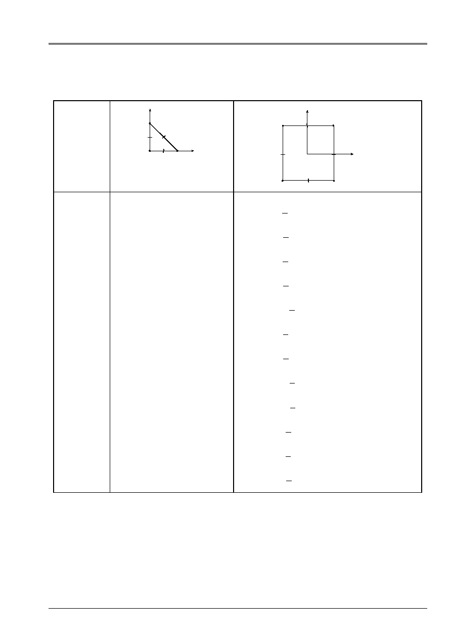
Code_Aster
®
Version
5.0
Titrate:
Elements of plate DKT, DST, DKQ, DSQ, Q4g
Date:
12/01/01
Author (S):
P. MASSIN
Key:
R3.07.03-A
Page:
35/54
Manual of Reference
R3.07 booklet: Machine elements on average surface
HI-75/01/001/A
where the functions of form are given for the triangle and the quadrangle in the following table:
1
2
3
4
5
6
DKT, DST
4
3
2
1
5
6
7
8
DKQ, DSQ, Q4
Interpolation
for W
= - -
1
i=1 with 9
NR
NR
NR
NR
NR
NR
NR
NR
NR
1
2
3
2
2
3
2
4
2
3
5
2
6
2
7
2
3
8
2
9
2
3
2
2
2
2
3
2
2
1
2
3
2
2
2
1
(,)
(,)
/
(,)
/
(,)
(,)
(
)
(,)
/
(,)
(,)
/
(,)
(
)
=
-
+
=
+
=
+
=
-
+
=
- + -
=
+
=
-
+
=
+
=
- + -
i=1 with 12
NR
NR
NR
NR
NR
NR
1
2
2
2
2
3
2
4
2
2
5
2
6
1
8 1
1
2
1
8 1
1
1
1
8 1
1
1
1
8 1
1
2
1
8 1
1
1
1
8 1
1
(,)
(
) (
) (
)
(,)
(
) (
) (
)
(,)
(
) (
) (
)
(,)
(
) (
) (
)
(,)
(
) (
) (
)
(,)
(
) (
=
-
-
-
-
- -
=
-
-
-
=
-
-
-
=
+
-
-
-
+ -
= -
+
-
-
=
+
-
) (
)
(,)
(
) (
) (
)
(,)
(
) (
) (
)
(,)
(
) (
) (
)
(,)
(
) (
) (
)
(,)
(
) (
) (
)
(,)
1
1
8 1
1
2
1
8 1
1
1
1
8 1
1
1
1
8 1
1
2
1
8 1
1
1
1
8
2
7
2
2
8
2
9
2
10
2
2
11
2
12
-
=
+
+
-
-
+ +
= -
+
+
-
= -
+
+
-
=
-
+
-
-
- +
=
-
+
-
=
NR
NR
NR
NR
NR
NR
(
) (
) (
)
1
1
1
2
-
+
-
Functions of interpolation for the arrow of elements DKT, DST, DKQ, DSQ and Q4G,
in dynamics and modal.

Code_Aster
®
Version
5.0
Titrate:
Elements of plate DKT, DST, DKQ, DSQ, Q4g
Date:
12/01/01
Author (S):
P. MASSIN
Key:
R3.07.03-A
Page:
36/54
Manual of Reference
R3.07 booklet: Machine elements on average surface
HI-75/01/001/A
4.5.2.1 Elements of type DKT
It is known that in the approximation of one Coils-Kirchhoff has
X
X
W
= -
,
and
y
y
W
= -
,
in any point of
the element.
Because of discretization stated above one a:
W
NR
W
J NR
J NR
W
J NR
J NR
W
K
NR
K
K
NR
K
NR
xk
K
NR
K
NR
K
NR
yk
=
+
+
+
+
-
+
-
+
-
+
-
+
=
-
+
(
)
(
)
(
)
,
(
)
(
)
,
(,)
(
(,)
(,))
(
(,)
(,))
1
1
11
1
2
21
1
3
12
1
2
1
22
1
3
since:
W
W
J
J
J
J
W
W
K
K
xk
yk
,
,
,
,
=
11
12
21
22
.
This is still written:
W
NR
W
NR
NR
K
NR
K
K
NR
xk
K
NR
yk
K
NR
=
+
+
-
+
-
+
-
+
=
(
)
(
)
(
)
(,)
(,)
(,)
1
1
1
2
1
3
1
where:
=
= -
-
= -
-
-
+
-
+
-
+
-
+
-
+
-
+
-
+
-
+
NR
NR
NR
J NR
J NR
NR
J NR
J NR
K
NR
K
NR
K
NR
K
NR
K
NR
K
NR
K
NR
K
NR
(
)
(
)
(
)
(
)
(
)
(
)
(
)
(
)
(,)
(,)
(,)
(,)
(,)
(,)
(,)
(,)
1
1
1
1
1
2
11
1
2
21
1
3
1
3
12
1
2
22
1
3
.
By not taking account of the effects of inertia, the matrix of mass has the following form thus:
M
M
M
M
=
m
m
F
0
0
0
0
0
0
where
M
NR NR
F
m
S
dS
=
.
4.5.2.2 Elements of the DST type
It is known that for these elements one has
X
X
X
W
=
-
,
and
y
y
y
W
=
-
,
where the distortion
is
constant on the element.
Like:
W
NR
W
J NR
J NR
W
J NR
J NR
W
K
NR
K
K
NR
K
NR
xk
K
NR
K
NR
K
NR
yk
=
+
+
+
+
-
+
-
+
-
+
-
+
=
-
+
(
)
(
)
(
)
,
(
)
(
)
,
(,)
(
(,)
(,))
(
(,)
(,))
1
1
11
1
2
21
1
3
12
1
2
1
22
1
3

Code_Aster
®
Version
5.0
Titrate:
Elements of plate DKT, DST, DKQ, DSQ, Q4g
Date:
12/01/01
Author (S):
P. MASSIN
Key:
R3.07.03-A
Page:
37/54
Manual of Reference
R3.07 booklet: Machine elements on average surface
HI-75/01/001/A
one can also write:
W
NR
W
NR
NR
J
J
NR
J
J
NR
K
NR
K
K
NR
xk
K
NR
yk
K
NR
X
y
K
NR
X
y
K
NR
=
+
+
+
+
+
+
-
+
-
+
-
+
=
-
+
-
+
(
)
(
)
(
)
(
)
(
)
(,)
(,)
(,)
(
)
(,) (
)
(,)
1
1
1
2
1
3
1
11
12
1
2
21
22
1
3
where:
=
= -
-
= -
-
-
+
-
+
-
+
-
+
-
+
-
+
-
+
-
+
NR
NR
NR
J NR
J NR
NR
J NR
J NR
K
NR
K
NR
K
NR
K
NR
K
NR
K
NR
K
NR
K
NR
(
)
(
)
(
)
(
)
(
)
(
)
(
)
(
)
(,)
(,)
(,)
(,)
(,)
(,)
(,)
(,)
1
1
1
1
1
2
11
1
2
21
1
3
1
3
12
1
2
22
1
3
,
NR
NR
NR
NR
NR
NR
K
NR
K
NR
K
NR
K
NR
K
NR
K
NR
K
NR
K
NR
K
NR
(
)
(
)
(
)
(
)
(
)
(
)
(,)
(,)
(,)
(,)
(,)
(,)
-
+
-
+
=
-
+
-
+
=
-
+
-
+
=
=
=
=
1
1
1
1
1
1
2
1
2
1
1
3
1
3
1
and
X
y
ct
C
C
X
y
NR
xN
yN
W
X
y
NR
xN
yN
W
W
W
W
=
+
=
-
H
B
B WITH
T
1
1
1
1
1
1
1
[
]
!
!
.
One obtains the interpolation for W then:
W
NR
W
NR
NR
K
NR
K
K
NR
xk
K
NR
yk
K
NR
=
+
+
-
+
-
+
-
+
=
(
)
(
)
(
)
(,)
(,)
(,)
1
1
1
2
1
3
1
where:
=
+
-
+ +
-
+
+
-
+ +
-
+
=
-
+
-
+
-
+
-
+
-
+
NR
NR
J T
K
NR
J T
K
NR
NR
J T
K
NR
J T
K
NR
NR
NR
K
NR
K
NR
W
W
J
NR
W
W
J
NR
K
NR
(
)
(
)
(
)
(
)
(
)
(,)
(,)
(
(, (
)
)
(, (
)
))
(,)
(
(, (
)
)
(, (
)
))
(,)
(,)
1
1
1
1
11
12
1
2
21
22
1
3
1
2
1
1
1
2
1
1
1
1
1
2
1
1
+
-
+ +
-
+
+
-
+ +
-
+
=
+
-
+
-
+
-
+
-
+
-
+
NR
J T
K
NR
J T
K
NR
NR
J T
K
NR
J T
K
NR
NR
NR
NR
K
NR
W
W
J
NR
W
W
J
NR
K
NR
K
NR
(
)
(
)
(
)
(
)
(
)
(,)
(
(, (
)
)
(, (
)
))
(,)
(
(, (
)
)
(, (
)
))
(,)
(,)
(,)
(
1
2
11
12
1
2
21
22
1
3
1
3
1
3
1
1
2
2
1
2
1
1
2
2
1
2
J T
K
NR
J T
K
NR
NR
J T
K
NR
J T
K
NR
NR
W
W
J
NR
W
W
J
NR
11
12
1
2
21
22
1
3
1
1
3
2
1
3
1
1
3
2
1
3
(, (
)
)
(, (
)
))
(,)
(
(, (
)
)
(, (
)
))
(,)
(
)
(
)
-
+ +
-
+
+
-
+ +
-
+
-
+
-
+

Code_Aster
®
Version
5.0
Titrate:
Elements of plate DKT, DST, DKQ, DSQ, Q4g
Date:
12/01/01
Author (S):
P. MASSIN
Key:
R3.07.03-A
Page:
38/54
Manual of Reference
R3.07 booklet: Machine elements on average surface
HI-75/01/001/A
By not taking account of the effects of inertia, the matrix of mass has the following form thus:
M
M
M
M
=
m
m
F
0
0
0
0
0
0
where
M
NR NR
F
m
S
dS
=
.
4.5.2.3 Elements of the Q4g type
One proceeds in the same way that for the elements of the DST type but with:
X
y
C
X
y
NR
xN
yN
W
W
=
B
1
1
1
!
where
B
C
is the matrix established with [§4.3.2.1].
4.5.2.4 Notice
One neglects in the form of the elementary matrix of mass the terms of inertia of
rotation
F
X
X
y
y
S
dS
($$
$$
)
+
because the latter are negligible [bib3] compared to the others. In
effect a multiplicative factor of H
2
/12 the dregs with the other terms and they become negligible for one
thickness report/ratio over characteristic length lower than 1/20.
4.5.3 Assembly of the elementary matrices of mass
The assembly of the matrices of mass follows same logic as that of the matrices of rigidity.
degrees of freedom are the same ones and one finds the processing specific to normal rotations to
plan of the plate. For modal calculations utilizing at the same time the calculation of the matrix of rigidity
and that of the matrix of mass, it is necessary to take a rigidity or a mass on the degree of rotation
normal in the plan of the plate of 10
3
to 10
6
time smaller than the diagonal minor term of the matrix
of rigidity or mass for the terms of bending. That makes it possible to inhibit the modes being able to appear
on the additional degree of freedom of rotation around the normal in the plan of the plate. By
defect, one takes a rigidity or a mass on the degree of normal rotation in the plan of plate 10
5
time smaller than the diagonal minor term of the matrix of rigidity or mass for the terms of
bending
4.5.4 Stamp of lumpée diagonal mass
The use of a matrix of lumpée diagonal mass has two advantages: it is simpler with
to implement numerically and it converges better. However the results are worse
that with the conventional diagram for which the error is minimal [bib5].

Code_Aster
®
Version
5.0
Titrate:
Elements of plate DKT, DST, DKQ, DSQ, Q4g
Date:
12/01/01
Author (S):
P. MASSIN
Key:
R3.07.03-A
Page:
39/54
Manual of Reference
R3.07 booklet: Machine elements on average surface
HI-75/01/001/A
The matrix of mass is made diagonal, for the degrees of translation, according to a technique of
lumping near to that developed by Hinton [bib6]. The advantage of this method is of always
to produce positive coefficients of mass, contrary to other methods like the summation
terms in column [bib5]. One uses the diagonal coefficients of the elementary matrix of mass
in the total reference mark by making sure that the total mass is well represented in each of the three
directions of translation:
m
M
dS
M
m
M
dS
M
m
M
dS
M
xi
X
xi
X
m
S
xj
J
NR
yi
y
yi
y
m
S
yj
J
NR
zi
Z
zi
Z
m
S
zj
J
NR
=
=
=
=
=
=
=
=
=
;
;;
;
1
1
1
where M
xi
, M
yi
, M
zi
are the diagonal terms of the elementary matrix of mass in the total reference mark,
in each of the three directions of translation. The matrix of mass obtained:
m
m
m
T
=
0
0
with
m
m
m
m
T
X
y
Z
=
0
0
0
0
0
0
and
m
=
0
is diagonal.
Note:
The creation of a matrix of diagonal mass in the directions of rotation with a technique
analog with that of the terms of translation (coefficients
I
are then the coefficients
previously defined in three directions X, y and Z) is inappropriate for the modal analysis and
the results obtained are for the moment better with a matrix of reduced diagonal mass
with the only degrees of translation. The difficulty of the use of this matrix arises then in
dynamics, when it is necessary to reverse the matrix of mass. One thus considers for the moment of
to make diagonal only the terms of translation and to preserve a matrix of mass
m
supplements for the terms of rotation.
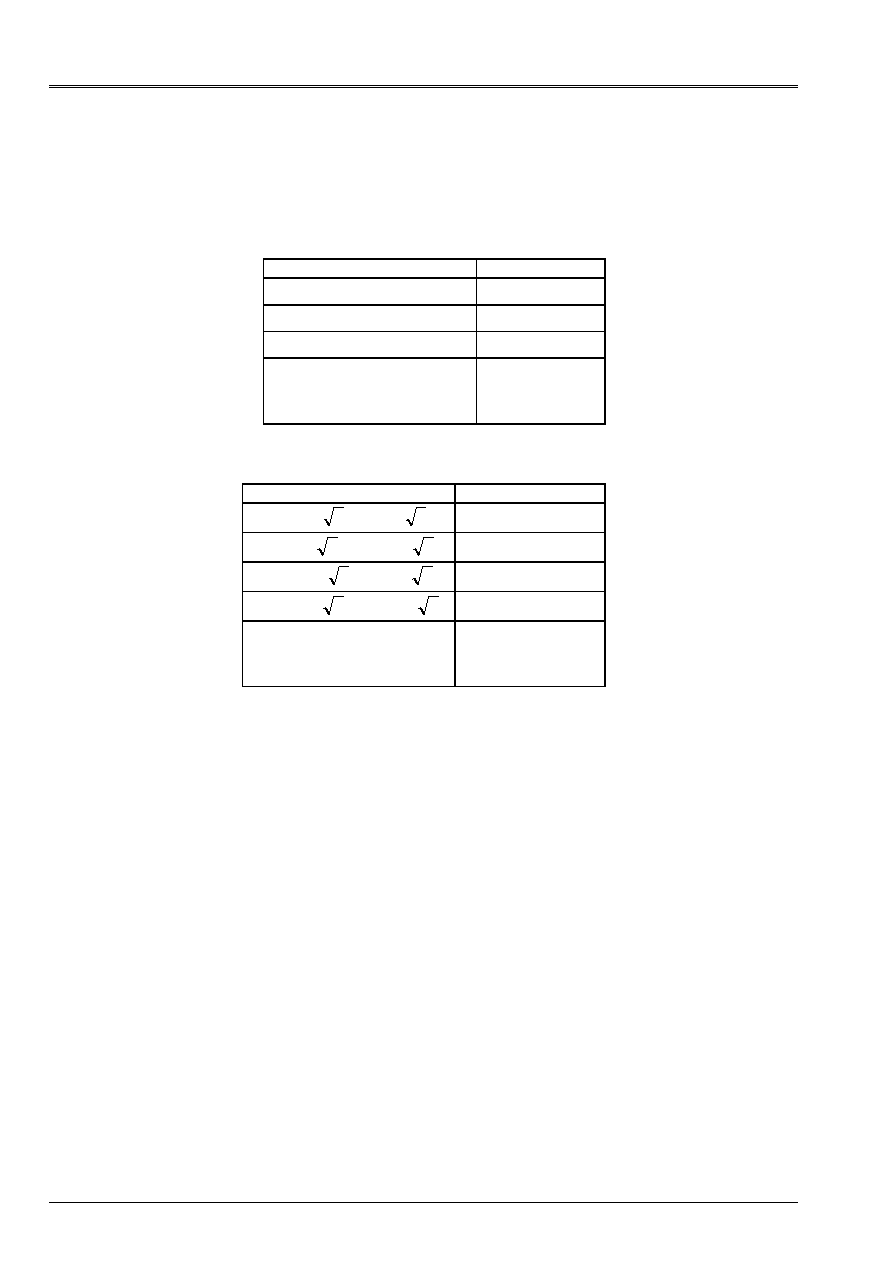
Code_Aster
®
Version
5.0
Titrate:
Elements of plate DKT, DST, DKQ, DSQ, Q4g
Date:
12/01/01
Author (S):
P. MASSIN
Key:
R3.07.03-A
Page:
40/54
Manual of Reference
R3.07 booklet: Machine elements on average surface
HI-75/01/001/A
4.6
Numerical integration for elasticity
For the triangular elements DKT, DST where [H] is constant, the matrices of rigidity are obtained
exactly with three points of integration of Hammer since [B] is linear in
.
Cordonnées of the points
Weight
1
1
1 6
1 6
=
=
/;
/
1/6
2
2
2 3
1 6
=
=
/;
/
1/6
3
3
1 6
2 3
=
=
/;
/
1/6
y
D D
(,)
=
-
0
1
0
1
I
I
I
I
N
y (,)
=
1
Numerical formulas of integration on a triangle (Hammer)
For the elements quadrangle an integration of Gauss 2x2 is used.
Cordonnées of the points
Weight
1
1
1
3
1
3
=
=
/
;
/
1
2
2
1
3
1
3
=
= -
/
;
/
1
3
3
1
3
1
3
= -
=
/
;
/
1
3
3
1
3
1
3
= -
= -
/
;
/
1
y
D D
(,)
=
-
0
1
0
1
I
I
I
I
N
y (,)
=
1
Numerical formulas of integration on a quadrangle (Gauss)
4.7
Numerical integration for plasticity
Integration on the surface of the element is supplemented by an integration on the thickness of
behavior since:
H
H
H
H
H
H
m
H
H
MF
F
H
H
H
H
dz
zdz
Z dz
=
=
=
-
+
-
+
-
+
,
/
/
/
/
/
/
2
2
2
2
2
2
2
,
where
H
is the plastic matrix of behavior
local.
The initial thickness is divided into NR identical layers thicknesses. There are three points of integration by
sleep. The points of integration are located in higher skin of layer, in the middle of the layer and
in lower skin of layer. For NR layers, the number of points of integration is of 2N+1. One
advise to use from 3 to 5 layers in the thickness for a number of points of integration being worth 7, 9
and 11 respectively.
For rigidity, one calculates for each layer, in plane stresses, the contribution to the matrices of
rigidity of membrane, bending and coupling membrane-bending. These contributions are added and
assemblies to obtain the matrix of total tangent rigidity.
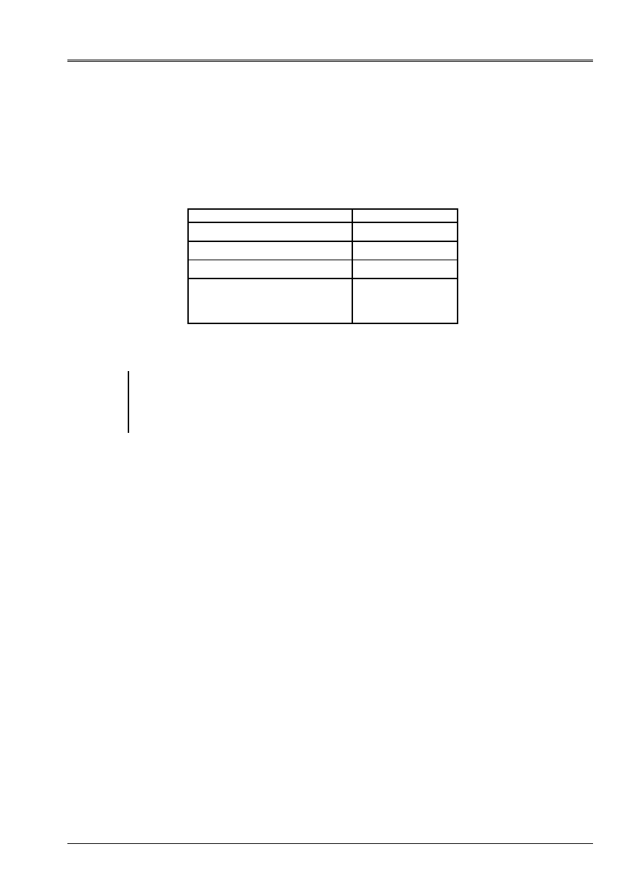
Code_Aster
®
Version
5.0
Titrate:
Elements of plate DKT, DST, DKQ, DSQ, Q4g
Date:
12/01/01
Author (S):
P. MASSIN
Key:
R3.07.03-A
Page:
41/54
Manual of Reference
R3.07 booklet: Machine elements on average surface
HI-75/01/001/A
For each layer, one calculates the state of the stresses
(
)
xx
yy
xy
,
,
and the whole of the variables
interns, in the middle of the layer and in skins higher and lower of layer, from
local plastic behavior and of the local field of deformation
(
)
xx
yy
xy
,
,
.
The positioning of
points of integration enables us to have the rightest estimates, because not extrapolated, in skins
lower and higher of layer, where it is known that the stresses are likely to be maximum.
Cordonnées of the points
Weight
1
1
= -
1/3
2
0
=
4/3
3
1
= +
1/3
y
D
()
=
-
1
1
I
I
I
I
N
y (,)
=
1
Formulate numerical integration for a layer in the thickness
Note:
One already mentioned with [§2.2.3] that the value of the coefficient of correction in shearing
transverse for the elements DST, DSQ and Q4
was obtained by identification of energies
complémenatires elastic after resolution of balance 3D. This method is not usable any more
in elastoplasticity and the choice of the coefficient of correction in transverse shearing is posed then.
Plasticity is thus not developed for these elements.
4.8
Discretization of external work
The variational formulation of work external for the elements of plate is written
:
µ
µ
W
F U
F v
F W m
m
dS
U
v
W
ds
ext.
X
y
Z
X
X
y
y
S
X
y
Z
X
X
y
y
C
=
+
+
+
+
+
+
+
+
+
(
)
(
)

Code_Aster
®
Version
5.0
Titrate:
Elements of plate DKT, DST, DKQ, DSQ, Q4g
Date:
12/01/01
Author (S):
P. MASSIN
Key:
R3.07.03-A
Page:
42/54
Manual of Reference
R3.07 booklet: Machine elements on average surface
HI-75/01/001/A
By taking account of a linear discretization of displacements, one can write for an element:
()
()
()
()
()
()
()
()
()
()
()
()
µ
µ
W
F NR
U
F NR
v
F NR
W
m NR
m NR
dS
NR
U
NR
v
NR
W
NR
NR
ds
F NR
dS
NR
ds
F NR
ext.
E
X
K
K
y
K
K
Z
K
K
S
K
NR
X
K
xk
y
K
yk
X
K
K
y
K
K
Z
K
K
C
X
K
xk
y
K
yk
X
K
X
K
C
S
y
K
=
+
+
+
+
+
+
+
+
+
=
+
=
(
,
,
,
,
,
)
(
,
,
,
,
,
)
,
,
1
()
()
()
()
()
()
()
()
)
,
,
,
,
,
,
,
,
µ
µ
dS
NR
ds
F NR
dS
NR
ds
m NR
dS
NR
ds
m NR
dS
NR
ds
y
K
C
S
K
NR
Z
K
Z
K
C
S
X
K
X
K
C
S
y
K
y
K
C
S
K
E
ke
ke
E
E
K
NR
+
+
+
+
=
=
=
=
1
1
U
F U
F U
The variational formulation of the work of the efforts external for the unit of the elements is written
then:
W
W
E
E
Nb elem
T
ext.
ext.
T
F U
U F
=
=
=
=
1
where
U
is the whole of the degrees of freedom of the structure
discretized and F comes from the assembly of the vectors forces elementary.
As for the matrices of rigidity, the process of assembly of the vectors forces elementary
imply that all the degrees of freedom are expressed in the total reference mark. In the total reference mark,
the degrees of freedom are three displacements compared to the three axes of the total Cartesian reference mark
and three rotations by report/ratio these three axes. One thus uses matrices of passage of the local reference mark
with the total reference mark for each element.
Note:
The external efforts can also be defined in the reference mark user. One then is used
stamp passage of the reference mark user towards the local reference mark of the element to have the expression of
these efforts in the local reference mark of the element and to deduce the vector from it forces elementary room
corresponding. For the assembly one passes then from the local reference mark of the element to the total reference mark.

Code_Aster
®
Version
5.0
Titrate:
Elements of plate DKT, DST, DKQ, DSQ, Q4g
Date:
12/01/01
Author (S):
P. MASSIN
Key:
R3.07.03-A
Page:
43/54
Manual of Reference
R3.07 booklet: Machine elements on average surface
HI-75/01/001/A
4.9
Taking into account of the thermal loadings
4.9.1 Thermo elasticity of the plates
The temperature is represented by the model of thermics to three fields according to [R3.11.01]:
(
)
()
()
()
()
()
()
T X
X
T
X
P X
T X
P X
T X
P X
m
S
I
,
.
.
.
3
1
3
2
3
3
3
=
+
+
,
with:
()
P X
J
3
: three polynomials of LAGRANGE in the thickness:
]
[
-
+
H
H
/,
/
2
2
:
()
(
)
()
(
)
()
(
)
P X
X
H
P X
X
H
X
H
P X
X
H
X
H
1
3
3
2
2
3
3
3
3
3
3
3
1
2
1 2
1 2
= -
=
+
= -
-
/
;
/
;
/
;
From the representation of the temperature above, one obtains:
·
the average temperature in the thickness:
()
(
)
() () ()
(
)
T X
H
T X
X dx
T
X
T X
T X
H
H
m
S
I
,
/
/
=
=
+
+
-
+
1
1
6 4
3
3
2
2
;
·
the average variation in temperature in the thickness:
()
(
)
() ()
%
,
/
/
T X
H
T X
X X dx
T X
T X
H
H
S
I
=
=
-
-
+
12
2
3
3
3
2
2
;
Thus the temperature can be written in the following way:
(
) () ()
(
)
T X
X
T X
T X
X
H T X
X
,
%
.
/
~
,
3
3
3
=
+
+
such as:
(
)
(
)
~
,
;
~
,
/
/
/
/
T X X
X T X X
H
H
H
H
3
2
2
3
3
2
2
0
0
-
-
=
=
.
If the temperature is indeed closely connected in the thickness one has,
~
T
=
0
.
Code_Aster treats three thermo situations elastic different, where characteristics
thermo rubber bands
E
,
,
depend only on the average temperature
T
in the thickness:
·
the case where the material is thermo homogeneous isotropic rubber band in the thickness;
·
the case where the plate modelizes an orthotropic grid (concrete reinforcing steels);
·
the case where the behavior of the plate is deduced from an elastic thermo homogenization,
cf [bib7].
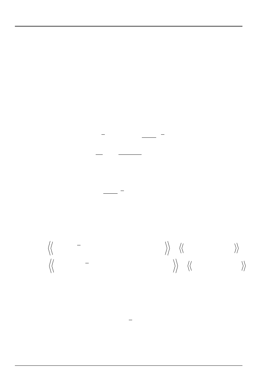
Code_Aster
®
Version
5.0
Titrate:
Elements of plate DKT, DST, DKQ, DSQ, Q4g
Date:
12/01/01
Author (S):
P. MASSIN
Key:
R3.07.03-A
Page:
44/54
Manual of Reference
R3.07 booklet: Machine elements on average surface
HI-75/01/001/A
For the elements of plate in thermo elasticity, the heating effects are taken into account by
the intermediate of generalized efforts, out of membrane and bending. Thus, in the case of a plate
homogeneous, knowing the expansion factor
, the generalized thermal efforts are defined in
to leave the plane stresses in the thickness by:
(
)
(
)
NR
C
dx
C
T T
dx
M
X C
dx
X C
T T
dx
V
ther
ther
H
H
ref.
H
H
ther
ther
H
H
ref.
H
H
ther
=
=
-
=
=
-
=
-
+
-
+
-
+
-
+
3
2
2
3
2
2
3
3
2
2
3
3
2
2
0
/
/
/
/
/
/
/
/
.
.
Maybe in the elastic thermo case isotropic homogeneous in the thickness:
(
)
(
)
(
)
NR
C
H T T
Eh
T T
M
C
H T
Eh
T
V
ther
ref.
ref.
ther
ther
=
-
=
-
-
=
=
-
=
.
.
.
.
;
.
.
%
.
.
%
;
.
1
12
12 1
0
2
2
2
2
The thermal stresses of origin withdrawn from the usual mechanical stresses are calculated
in three positions (sup., moy. and inf.) in the thickness:
(
)
ther
ref.
E T T
T X
H
= -
-
+
.
%.
/
1
2
3
In the case deduced from the elastic thermo homogenization, cf [bib7], the thermal efforts generalized
are defined by the general relation, starting from the “correctors” of membrane
, those of
bending
, and that of dilation
U
dil
, like averages on representative elementary volume
(airframe Z):
()
(
)
(
)
()
()
()
(
)
(
)
()
()
NR
C
T T
T X
Z
H T X
X
C
M
Z C
T T
T X
Z
H T X
X
C
V
ther
ref.
ij
ijkl
kl
dil
ther
ref.
ij
ijkl
kl
dil
ther
=
-
+
+
+
=
-
+
+
+
=
.
%
.
/
~
,
.
;
.
.
%
.
/
~
,
.
;
3
3
3
3
3
0
Z
Z
Z
Z
U
U
In this case when one limits oneself to the orthotropic situations without coupling bending-membrane, one
neglect the role of
(
)
~
,
T X X
3
on the corrector
U
dil
, and it is thus found that the thermal efforts which
appear to the second member have as an expression:
(
)
NR
H
T
T
M
H
T
V
ther
m
ref.
ther
F
ther
=
-
=
=
.
.
;
.
.
%
;
0

Code_Aster
®
Version
5.0
Titrate:
Elements of plate DKT, DST, DKQ, DSQ, Q4g
Date:
12/01/01
Author (S):
P. MASSIN
Key:
R3.07.03-A
Page:
45/54
Manual of Reference
R3.07 booklet: Machine elements on average surface
HI-75/01/001/A
One cannot however go up with the complete three-dimensional stresses: it would be necessary of
to know the “correctors” within the basic airframe having been used for the determination of
coefficients of homogenized behavior.
In the elastoplastic thermo situations, or for the hulls (elements of the family
COQUE_3D
), it is necessary to evaluate the three-dimensional stresses, of which stresses
thermics, in each point of integration in the thickness.
Note:
To go up with the complete three-dimensional stresses is not immediate for the hulls
multi-layer (laminated) because it is necessary to know layer by layer the state of stress; in elasticity,
the aforementioned results from the state of deformation and the behavior on the level of each layer.
4.9.2 Chaining
thermomechanics
For the resolution of chained thermomechanical problems, one must use for thermal calculation
finite elements of thermal hull [R3.11.01] whose field of temperature is recovered like
input datum of Code_Aster for mechanical calculation. It is necessary thus that there is compatibility between
thermal field given by the thermal hulls and that recovered by the mechanical plates. It
the last is defined by the knowledge of the 3 fields
TEMP_SUP
,
TEMP
and
TEMP_INF
given in skins
lower, medium and higher of hull.
The table below indicates compatibilities between the elements of plate and the elements of hull
thermics:
Modeling
THERMICS
Net
Finite element
to use
with
Net
Finite element
Modeling
MECHANICS
HULL
QUAD4 THCOQU4
//////////////
///////////////
/////////////
QUAD4
MEDKQU4
MEDSQU4
MEQ4QU4
DKT
DST
Q4
HULL
TRIA3
THCOTR3
///////////////
/////////////
TRIA3
MEDKTR3
MEDSTR3
DKT
DST
Note:
The nodes of the thermal elements of hulls and mechanical plates must
to correspond. The mesh will be identical.
The elements of thermal hulls surface are treated like plane elements by
projection of the initial geometry on the level defined by the first 3 nodes.
The chaining with definite multi-layer materials via the control
DEFI_COQU_MULT
[U4.23.03]
is not available for the moment.
The thermomechanical chaining is also possible if one knows by experimental measurements
variation of the field of temperature in the thickness of the structure or certain parts of
structure. In this case one works with a card of temperature defined a priori; the field of
temperature is not given any more by the three values
TEMP_INF
,
TEMP
and
TEMP_SUP
thermal calculation
obtained by
EVOL_THER
. It can be much richer and contain an arbitrary number of points
of discretization in the thickness of the hull. The operator
DEFI_NAPPE
allows to create such profiles
temperatures starting from the data provided by the user. These profiles are affected by
order
AFFE_CARTE
(cf the case-test hsns100b). It will be noted that it is not necessary for calculation
mechanics that the number of points of integration in the thickness is equal to the number of points of
discretization of the field of temperature in the thickness. The field of temperature is
automatically interpolated at the points of integration in the thickness of the elements of plates or of
hulls.
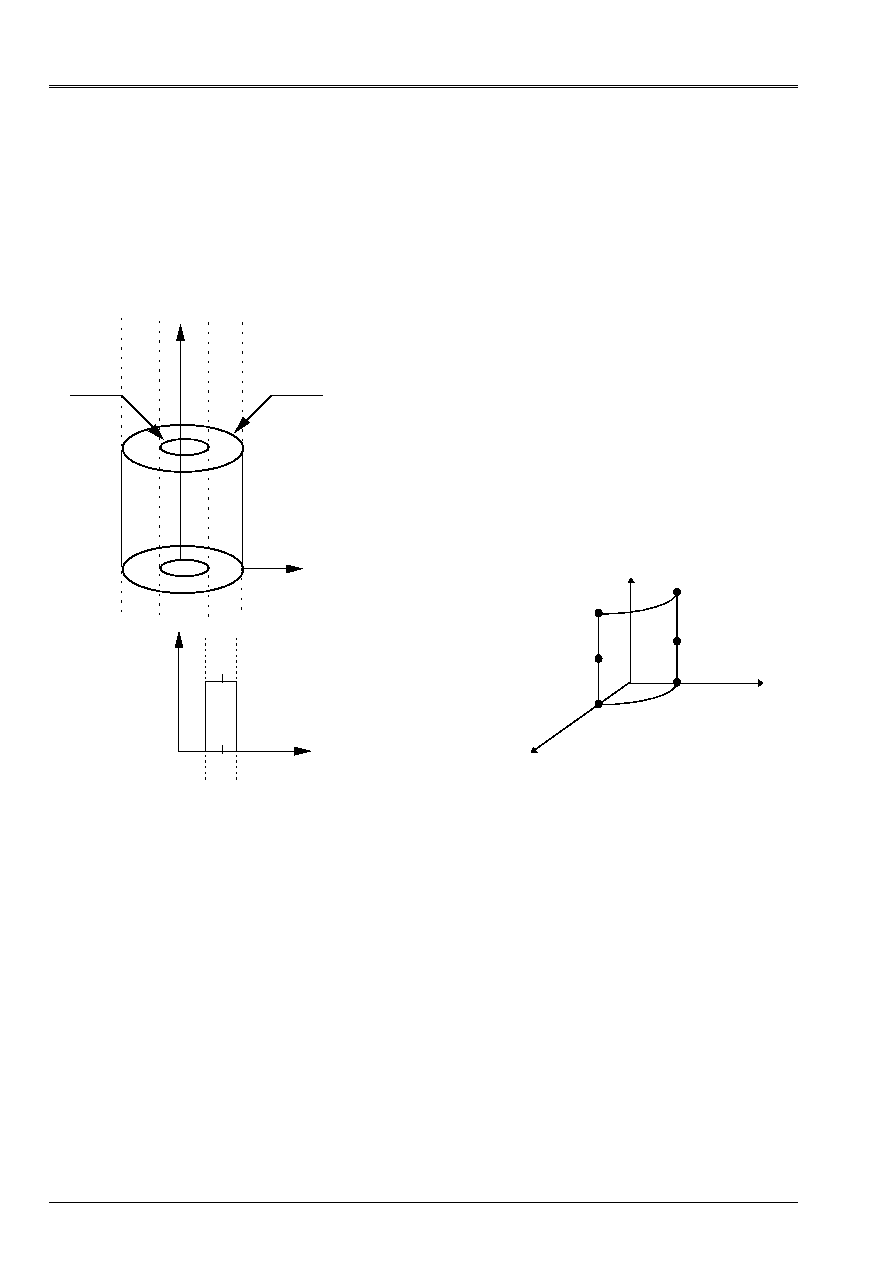
Code_Aster
®
Version
5.0
Titrate:
Elements of plate DKT, DST, DKQ, DSQ, Q4g
Date:
12/01/01
Author (S):
P. MASSIN
Key:
R3.07.03-A
Page:
46/54
Manual of Reference
R3.07 booklet: Machine elements on average surface
HI-75/01/001/A
4.9.3 Case-test
The case-tests for the thermomechanical chaining enters of the thermal elements of hulls and of
elements of plate are the hpla100e (elements DKT) and hpla100f (elements DKQ). It is about a cylinder
heavy thermoelastic hollow in uniform rotation [V7.01.100] subjected to a phenomenon of dilation
thermics where the fields of temperature are calculated with
THER_LINEAIRE
by a calculation
stationary.
Z
R
R
E
R
I
F
B
D
With
C
R
Z
J
H
+
Interior radius
R
I
= 19.5 mm
External radius
R
E
= 20.5 mm
Not F
R = 20.0 mm
Thickness
H = 1.0 mm
Height
L = 10.0 mm
y
Z
X
K
L
M
NR
P
Q
Thermal dilation is worth:
()
()
(
) (
)
(
)
T
T
T
T
T
T R R H
ref.
S
I
S
I
-
=
+
+
+
-
0 5
2
.
.
/
with:
·
T
C
T
C
T
C
S
I
ref.
=
°
= -
°
=
°
0 5
0 5
0
.
,
.
,
.
·
T
C
T
C
T
C
S
I
ref.
=
°
=
°
=
°
01
01
0
.
,
.
,
.
One tests the stresses, the efforts and bending moments in L and Mr. the results of reference are
analytical. One obtains very good results whatever the type of element considered.

Code_Aster
®
Version
5.0
Titrate:
Elements of plate DKT, DST, DKQ, DSQ, Q4g
Date:
12/01/01
Author (S):
P. MASSIN
Key:
R3.07.03-A
Page:
47/54
Manual of Reference
R3.07 booklet: Machine elements on average surface
HI-75/01/001/A
5
Establishment of the elements of plate in Code_Aster
5.1 Description
:
These elements (of names
MEDKTR3
,
MEDSTR3
,
MEDKQU4
,
MEDSQU4
and
MEQ4QU4
) rest on
meshs
TRIA3
and
QUAD4
plane. These elements are not exact with the nodes and it is necessary to net with
several elements to obtain correct results.
5.2
Introduced use and developments:
These elements are used in the following way:
·
AFFE_MODELE (MODELING: “DKT”.)
for the triangle and the quadrangle of the type DKT
·
AFFE_MODELE (MODELING: “DST”.)
for the triangle and the quadrangle of the DST type
·
AFFE_MODELE (MODELING: “Q4G”.)
One calls upon the routine
INI079
for the position of the points of Hammer and Gauss on the surface of
plate and the corresponding weights.
·
AFFE_CARA_ELEM (HULL:(THICKNESS:“EP”
ANGL_REP: ('
''
')
COEF_RIGI_DRZ: “CTOR”)
To make postprocessings (forced, generalized efforts,…) in a reference mark chosen by the user
who is not the local reference mark of the element, one gives a direction of reference D defined by two angles
nautical in the total reference mark. The projection of this direction of reference in the field of the fixed plate
a X1 direction of reference. The normal in the plan into fixed one second and the vector product of both
vectors previously definite makes it possible to define the local trihedron in which the efforts will be expressed
generalized and stresses. The user will have to take care that the selected reference axis is not found
not parallel with the normal of certain elements of plate of the model. By defect this direction of
reference is axis X of the total reference mark of definition of the mesh.
The value
CTOR
corresponds to coefficent that the user can introduce for the processing of the terms of
rigidity and of mass according to normal rotation in the plan of the plate. This coefficient must be sufficiently
small not to disturb the energy balance of the element and not too small so that matrices of
rigidity and of mass are invertible. A value of 10
5
is put by defect.
·
ELAS: (E:NAKED Young:
ALPHA:
. RHO:
. )
For an elastic thermo behavior isotropic homogeneous in the thickness one uses the key word
ELAS
in
DEFI_MATERIAU
where one defines the coefficients E, modulus Young,
,
Poisson's ratio,
,
thermal expansion factor and
RHO
density
.
·
ELAS_ORTH (_FO): (
E_L:ygl. E_T:ygt. .G_LT:glt. G_TZ:gtz. .NU_LT:nult.
ALPHA_L:
L. ALPHA_T:
T.)

Code_Aster
®
Version
5.0
Titrate:
Elements of plate DKT, DST, DKQ, DSQ, Q4g
Date:
12/01/01
Author (S):
P. MASSIN
Key:
R3.07.03-A
Page:
48/54
Manual of Reference
R3.07 booklet: Machine elements on average surface
HI-75/01/001/A
For a thermo behavior elastic orthotropic whose axes of orthotropism are L, T and Z with
isotropy of axis L (fibers in the direction L coated by a matrix, for example) the seven should be given
independent coefficients
ygl
, longitudinal Young modulus,
ygt
, transverse Young modulus,
glt
,
modulus of rigidity in plan LT,
gtz
, modulus of rigidity in plan TZ
nult
, coefficient of
Poisson in plan LT and the expansion factors thermal
L
and
T
for thermal dilation
longitudinal and transverse, respectively. The orthotropic behavior is not available
that associated the key word
DEFI_COQU_MULT
who allows to define a multi-layer composite hull.
For only one orthotropic material, one will thus use
DEFI_COQU_MULT
with only one layer. If one
wish to use
ELAS_ORTH
for transverse shearing, it is necessarily necessary to employ
DST modeling. If modeling DKT is used, transverse shearing is not taken into account.
·
ELAS_COQUE (_FO): (
MEMB_L:C1111. MEMB_LT:C1122. MEMB_T:C2222. MEMB_G_LT:C1212.
FLEX_L:D1111. FLEX_LT:D1122. FLEX_T:D2222. FLEX_G_LT:D1212.
CISA_L:G11…. CISA_T:G22…. ALPHA:
. RHO:
. )
This behavior was added in
DEFI_MATERIAU
to take into account matrices of rigidity
nonproportional in rigidity and bending, obtained by homogenization of a multi-layer material.
The coefficients of the matrices of rigidity are then introduced with the hand by the user into the reference mark
user defined by the key word
ANGL_REP
. The thickness given in
AFFE_CARA_ELEM
is only
used with the density defined by
RHO. ALPHA
is thermal dilation. If one wishes
to use
ELAS_COQUE
for transverse shearing, it is necessarily necessary to employ modeling
DST. If modeling DKT is used, transverse shearing is not taken into account.
·
DEFI_COQU_MULT: (LAYER: THICKNESS:“EP”
MATER: “material”
ORIENTATION: ('
'))
This key word makes it possible to define a multi-layer composite hull on the basis of the sub-base towards
roadbase starting from its characteristics sleeps by layer, thickness, type of material
constitutive and orientation of fibers compared to a reference axis. The type of constitutive material is
product by the operator
DEFI_MATERIAU
under the key word
ELAS_ORTH
.
is the angle of the first
direction of orthotropism (longitudinal direction or direction of fibers) in the tangent plan with the element by report/ratio
with the first direction of the reference mark of reference defined by
ANGL_REP
. By defect
is null, if not it must be
provided in degrees and must lie between 90º and + 90º.
·
AFFE_CHAR_MECA (DDL_IMPO: (
DX:. DY:. DZ:. DRX:. DRY:. DRZ:.
DDL of plate in the reference mark
total.
FORCE_COQUE: (FX:. FY:. FZ:. MX:. MY:. MZ:. )
They are the efforts
surface on elements of plate. These efforts can be given in the total reference mark or
in the reference mark user defined by
ANGL_REP
.
·
FORCE_NODALE: (FX:. FY:. FZ:. MX:. MY:. MZ:. )
It is about
efforts of hull in the total reference mark.
5.3
Calculation in linear elasticity:
The matrix of rigidity and the matrix of mass (respectively options
RIGI_MECA
and
MASS_MECA
)
are integrated numerically
.
It is not checked if the mesh is plane or not. Calculation holds account
owing to the fact that the terms corresponding to the DDL of plate are expressed in the local reference mark of
the element. A matrix of passage makes it possible to pass from the local DDL to the total DDL.

Code_Aster
®
Version
5.0
Titrate:
Elements of plate DKT, DST, DKQ, DSQ, Q4g
Date:
12/01/01
Author (S):
P. MASSIN
Key:
R3.07.03-A
Page:
49/54
Manual of Reference
R3.07 booklet: Machine elements on average surface
HI-75/01/001/A
Elementary calculations (
CALC_ELEM
) currently available correspond to the options:
·
EPSI_ELNO_DEPL
and
SIGM_ELNO_DEPL
who provide the strains and the stresses
with the nodes in the reference mark user of the element in lower skin, with semi thickness and in
higher skin of plate, the position being specified by the user
.
These values are stored
in the following way: 6 components of strain or stresses:
·
EPXX EPYY EPZZ EPXY EPXZ EPYZ
or
SIXX SIYY SIZZ SIXY SIXZ SIYZ
·
DEGE_ELNO_DEPL
: who gives the deformations generalized by `element to the nodes to
to leave displacements in the reference mark user:
EXX, EYY, EXY, KXX, KYY, KXY,
GAX, GAY.
·
EFGE_ELNO_DEPL
: who gives the efforts generalize by element with the nodes from
displacements:
NXX, NYY, NXY, MXX, MYY, MXY, QX, QY
.
·
SIEF_ELGA_DEPL
: who gives the efforts generalize by element at the points of Gauss with
to leave displacements:
NXX, NYY, NXY, MXX, MYY, MXY, QX, QY
.
·
EPOT_ELEM_DEPL
: who gives the elastic energy of deformation per element from
displacements.
·
ECIN_ELEM_DEPL
: who gives the kinetic energy by element.
Finally one calculates also the option
FORC_NODA
of calculation of the nodal forces for the operator
CALC_NO
.
5.4
Plastic design
The matrix of rigidity is there too integrated numerically. One calls upon the option of calculation
STAT_NON_LINE
in which one defines in the level of the nonlinear behavior the number of
layers to be used for numerical integration. All laws of plane stresses available in
Code_Aster can be used.
STAT_NON_LINE (….
COMP_INCR: (RELATION:''
COQUE_NCOU:“A NUMBER OF LAYERS”)
….)
Elementary calculations (
CALC_ELEM
) currently available correspond to the options:
·
EPSI_ELNO_DEPL
who provides the deformations by element to the nodes in the reference mark
user starting from displacements, in lower skin, with semi thickness and in higher skin
of plate.
·
SIGM_ELNO_COQU
who allows to obtain the stress field in the thickness by element
with the nodes for a given layer and a position requested (in lower skin, in the medium
or in higher skin of layer). These values are given in the reference mark user.
·
SIEF_ELNO_ELGA
who allows to obtain the efforts generalized by element with the nodes in
the reference mark user.
·
VARI_ELNO_ELGA
who calculates the field of internal variables and the stresses by element
with the nodes for all the layers, in the local reference mark of the element.

Code_Aster
®
Version
5.0
Titrate:
Elements of plate DKT, DST, DKQ, DSQ, Q4g
Date:
12/01/01
Author (S):
P. MASSIN
Key:
R3.07.03-A
Page:
50/54
Manual of Reference
R3.07 booklet: Machine elements on average surface
HI-75/01/001/A
6 Conclusion
The finite elements of plate plans which we describe here are used in the structural analyzes
thin, in small displacements and deformations, of which the thickness report/ratio over characteristic length
is lower than 1/10. As these elements are plane, they do not take into account the curvature of
structures, and it is necessary to refine the mesh if the aforementioned would be important.
It is elements for which strains and stresses in the plan of the element
vary linearly with the thickness of the plate. Moreover, the distortion associated with shearing
transverse is constant in the thickness of the element. Two types of elements of plate exist:
elements DKT, DKQ for which the transverse distortion is null and the elements DST, DSQ and Q4
for which it remains constant and nonnull in the thickness. One advises to use the second type
elements when the structure to be netted has a thickness report/ratio over characteristic length included/understood
between 1/20 and 1/10 and first in the remainder of the cases. When the transverse distortion is not
null, elements of DST plate, DSQ and Q4
the equilibrium conditions 3D and they do not satisfy
boundary conditions on the nullity of stresses shear transverse on the faces higher
and lower of plate, compatible with a constant transverse distortion in the thickness of
plate. It results from it thus that on the level from the behavior a coefficient from 5/6 for a plate
homogeneous the usual relation between the stresses and the distortion transverses corrects in order to
to ensure the equality enters energies of shearing of the model 3D and the model of plate to distortion
constant. In this case, the arrow W has as an interpretation average transverse displacement in
the thickness of the plate.
The non-linear behaviors in plane stresses are available for the elements of plate
DKT and DKQ only. Indeed the rigorous taking into account of a constant transverse shearing
not no one on the thickness and the determination of the correction associated on rigidity with shearing by
report/ratio with a model satisfying the equilibrium conditions and the boundary conditions are not
possible and thus the use of the DST elements, DSQ and Q4 return
rigorously impossible in
plasticity.
Elements corresponding to the machine elements exist in thermics; chainings
thermo mechanics is thus available except, for the moment, laminated materials.

Code_Aster
®
Version
5.0
Titrate:
Elements of plate DKT, DST, DKQ, DSQ, Q4g
Date:
12/01/01
Author (S):
P. MASSIN
Key:
R3.07.03-A
Page:
51/54
Manual of Reference
R3.07 booklet: Machine elements on average surface
HI-75/01/001/A
7 Bibliography
[1]
J.L. Batoz, G.Dhatt, “Modeling of the structures by finite elements: beams and plates”,
Hermès, Paris, 1992.
[2]
D. Bui, “shearing in the plates and hulls: modeling and calculation”, Note HI-
71/7784, 1992.
[3]
J.G. Ren, “A new theory off laminated punt”, Composite Science and Technology, Vol.26,
p.225-239,1986.
[4]
T.A. Rock'n'roll, E. Hinton, “A finite element method for the free vibration off punts Al for
transverse shear deformation “, Computers and Structures, Vol.6, p.37-44,1976.
[5]
T.J.R. Hughes, “The finite element method”, Prentice Hall, 1987.
[6]
E. Hinton, T. Rock'n'roll and O.C. Zienkiewicz, “A notes one Farmhouse Lumping and Related Processes in
the Finite Element Method “, Earthquake Engineering and Structural Dynamics, Vol4, p. 245-
249, 1976.
[7]
F. Voldoire “Modeling by thermal and thermo homogenization elastic of components
mean mechanics ", CR MN/97/091.
[8]
R3.11.01 P. MASSIN, F. VOLDOIRE, S. ANDRIEUX “Models of thermics for the hulls
thin ", Manual of reference of Code_Aster.
[9]
V7.01.100 F. VOLDOIRE “thermoelastic Hollow roll”, Manual of validation of
Code_Aster.
[10]
A.K. Noor, W.S. Burton, “Assessment off shear deformation theories for multilayered
composite punts “, ASME, Applied Mechanics Review, Vol.42, N°1, p.1-13,1989.
[11]
A.K. Noor, W.S. Burton, J.M. Peters “Assessment off computational models for multilayered
composite cylinders “in Analytical and Computational Models off Shells, Noor and Al Eds,
ASME, CED - Vol.3, P.419-442,1989.
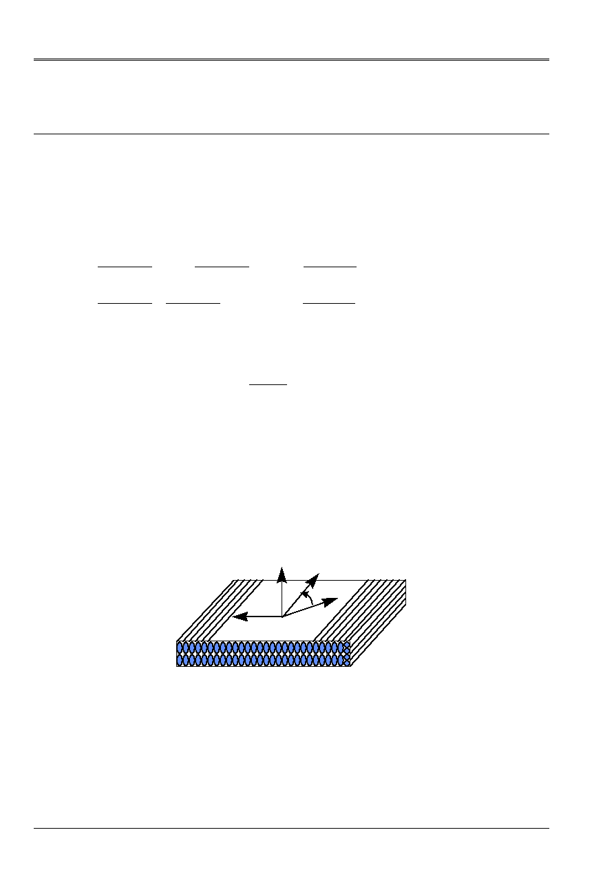
Code_Aster
®
Version
5.0
Titrate:
Elements of plate DKT, DST, DKQ, DSQ, Q4g
Date:
12/01/01
Author (S):
P. MASSIN
Key:
R3.07.03-A
Page:
52/54
Manual of Reference
R3.07 booklet: Machine elements on average surface
HI-75/01/001/A
Appendix 1 orthotropic Plates
For an orthotropic material like that represented below, composed for example of fibers of direction L
coated with a matrix, whose axes of orthotropism are L, T and Z with isotropy of axis L, the expression for
matrices
H
and
H
in the reference mark of orthotropism previously definite becomes:
H
L
=
H
H
H
H
G
L
LT
LT
TT
LT
0
0
0
0
and
H
L
=
G
G
LZ
TZ
0
0
with
H
E
H
E
H
E
E
L
L
LT TL
TT
T
LT TL
LT
T LT
LT TL
L TL
LT TL
= -
= -
= -
= -
1
1
1
1
;
and
G
E
G
E
LZ
L
LZ
TZ
T
TZ
=
+
=
+
2 1
2 1
(
)
(
)
.
The knowledge of the five independent coefficients
E
E G
G
L
T
LT
TZ
LT
,
,
,
,
is sufficient to determine
coefficients of the matrices
H
and
H
since:
TL
T LT
L
E
E
=
and
G
G
LZ
LT
=
.
If one indicates by
the angle enters the reference mark of orthotropism and the principal axis of the reference mark defined by the user in
means of
ANGL_REP
it is established that:
H T H T
1T
L 1
=
and
H
T H
T
2T
L
2
=
with:
T
1
=
-
-
-
C
S
CS
S
C
CS
CS
CS C
S
2
2
2
2
2
2
2
2
and
T
2
= -
C
S
S C
where
C
S
=
=
cos,
sin
and
=
(,)
X L
like
indicated on the figure below.
X
T
L
Z
In the case of forced initial of thermal origin, we have moreover:
HT
L
T
T
T
= -
T H
1T
L
0
where
L
and
T
are the expansion factors thermal in the directions L and T and
T variation of
temperature.

Code_Aster
®
Version
5.0
Titrate:
Elements of plate DKT, DST, DKQ, DSQ, Q4g
Date:
12/01/01
Author (S):
P. MASSIN
Key:
R3.07.03-A
Page:
53/54
Manual of Reference
R3.07 booklet: Machine elements on average surface
HI-75/01/001/A
Appendix 2 Factors of transverse correction of shearing for
orthotropic or laminated plates
The matrix
H
ct
is defined so that the surface density of transverse energy of shearing obtained in
the case of the three-dimensional distribution of the stresses resulting from the resolution of balance is equal to that
model of plate based on the assumptions of Reissner, for a behavior in pure bending. One must
thus to find
H
ct
such as:
1
2
1
2
1
2
2
2
H
TH T
H
1
ct1
ct
-
-
+
-
=
=
H
H
/
/
with
=
xz
yz
and
T
H
ct
=
=
-
+
dz
H
H
/
/
2
2
.
To obtain
H
ct
one uses the distribution of
according to Z obtained starting from the resolution of the equations
of balance 3D without external couples:
xz
xx X
xy y
H
Z
yz
xy X
yy y
H
Z
D
D
= -
+
= -
+
-
-
(
)
;
(
)
,
,
/
,
,
/
2
2
with
xz
yz
=
=
0
for z=±h/2.
If there is no coupling membrane bending (symmetry compared to z=0), stresses in
plan of the element
xx
yy
xy
,
,
in the case of have as an expression a behavior of pure bending:
=
Z
Z
With
M
()
with
With
H
H
F 1
()
()
Z
Z
=
-
.
If
()
H Z
and
H
F
do not depend on X and y one can determine
H
ct
. Indeed:
()
()
()
Z
Z
Z
=
+
D
T D
1
2
where
T
= =
+
+
T
T
M
M
M
M
X
y
xx X
xy y
xy X
yy y
,
,
,
,
and
=
-
-
M
M
M
M
M
M
xx X
xy y
xy X
yy y
yy X
xx y
,
,
,
,
,
,
like:
D
1
= -
+
+
+
+
-
2
11
33
13
32
31
23
22
33
2
With
With
With
With
With
With
With
With D
H
Z
/
,
D
2
= -
-
-
-
-
-
2
2
2
2
2
11
33
13
32
12
31
31
23
33
22
32
21
2
With
With
With
With
With
With
With
With
With
With
With
With D
H
Z
/
.
It results from it that
1
2
1
2
2
2
-
+
-
=
H
H
/
/
H
T C
C
C
C
T
1
11
12
12
T
22
with:
C
D H D
C
D H D
C
D H D
11
1
T
1 1
12
1
T
1 2
22
2
T
1
2
=
=
=
-
+
-
-
-
+
-
+
-
H
H
H
H
H
H
dz
dz
dz
/
/
/
/
/
/
;
;
2
2
2
2
2
2

Code_Aster
®
Version
5.0
Titrate:
Elements of plate DKT, DST, DKQ, DSQ, Q4g
Date:
12/01/01
Author (S):
P. MASSIN
Key:
R3.07.03-A
Page:
54/54
Manual of Reference
R3.07 booklet: Machine elements on average surface
HI-75/01/001/A
As in addition
1
2
1
2
2
2
-
+
-
-
=
H
H
/
/
H
TH T
1
ct1
one proposes to take
H
C
ct
111
=
-
to satisfy them as well as possible
two equations whatever T and
.
While comparing
H
ct
thus calculated with
H
H
ct
=
-
+
dz
H
H
/
/
2
2
one reveals the coefficients of correction of
following transverse shearing:
K
H
H
K
H
H
K
H
H
ct
ct
ct
ct
ct
ct
1
11
11 12
12
12
2
22
22
=
=
=
/
;
/
;
/
.
For a homogeneous, isotropic or anisotropic plate, one finds as follows:
H
ct
=kh
H
with k=5/6.
Note:
This method is valid only when the composite plate is symmetrical compared to z=0.
·
For a multi-layer material, one establishes that:
C
With
WITH H
With
With
WITH H
With
With
With
WITH H A
11
p
T
I
T
1
p
I
I
T
1
p
I
Pt
I
T
1
I
=
-
-
+
-
-
+
-
+
-
=
-
-
=
=
-
+
-
=
-
=
-
-
+
H
H
Z
H
Z
Z
Z
H
Z
H
Z
Z
Z
I
p p
p
I
I
I
NR
p p
p
I
I
I
I
p p
p
I
I
p p
p
I
I
I
I
4
1
2
1
2
1
24
1
2
1
2
1
80
1
1
2
1
1
1
2
1
3
3
1
1
2
1
1
2
1
5
5
(
)
(
)
(
) [
(
) (
)
]
(
) A H A
I
T
1
I
-
where:
(
)
H
Z
Z
Z
Z
I
I
I
I
I
I
=
-
=
+
+
+
1
1
1
2
,
and
With
I
represent the matrix
With
With
With
With
With
With
With
With
11
33
13
32
31
23
22
33
+
+
+
+
for
layer I.
·
Validity of the choice
H
C
ct
111
=
-
can be examined a posteriori when one has an estimate of
solution (fields of displacements and plane stresses, in particular). One can then estimate
the variation enters the two estimates on energy. A step of calculation in two stages for
multi-layer plates and hulls (with
H
ct
diagonal and two coefficients K
1
and K
2
) was besides
developed by Noor and Burton [bib11] [bib12].
·
In the case of an isotropic or anisotropic homogeneous plate the equality between two energies is
satisfied in a strict sense since D
2
= 0. The choice makes above is then valid and no examination has
posteriori is not necessary.