
Code_Aster
®
Version
7.4
Titrate:
An example of use of Code_Aster: calculation of a bent pipe
Date:
18/05/05
Author (S):
Mr. ABBAS, J.M. PROIX
Key
:
U1.05.01-B
Page
:
1/10
Instruction manual
U1.0- booklet: Introduction to Code_Aster
HT-66/05/004/A
Organization (S):
EDF-R & D/AMA
Instruction manual
U1.0- booklet: Introduction to Code_Aster
Document: U1.05.01
An example of use of Code_Aster:
calculation of a bent pipe
Summary:
This document describes a simple example of use of Code_Aster which is provided with the procedure of
downloading of Code_Aster since the site code-aster.org.
Code_Aster
®
Version
7.4
Titrate:
An example of use of Code_Aster: calculation of a bent pipe
Date:
18/05/05
Author (S):
Mr. ABBAS, J.M. PROIX
Key
:
U1.05.01-B
Page
:
2/10
Instruction manual
U1.0- booklet: Introduction to Code_Aster
HT-66/05/004/A
1
Facts of the case
1.1 Geometry
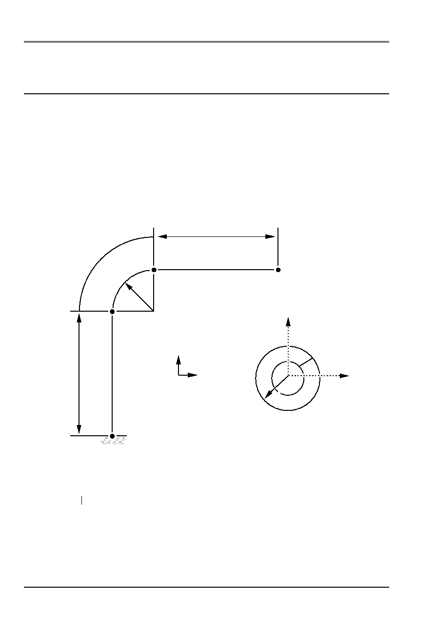
The study relates to a piping including/understanding two right pipes and an elbow [Figure 1.1-a].
The geometrical data of the problem are as follows:
·
the length L
G
the two right pipes is 3 m,
·
the Rc radius of the elbow is 0.6 m,
·
the angle
elbow is 90 degrees,
·
the thickness of the right pipes and the elbow is 0.02 m,
·
and the radius external Re of the right pipes and the elbow is of 0.2 Mr.
L
G
L
G
R
C
section B
section D
section C
section A
O
Y
X
Z
Re
X
Z
E
C
D
B
With
Appear 1.1-a
Note:
The geometry of the problem has a symmetry compared to the plan (A, X, Y).
Code_Aster
®
Version
7.4
Titrate:
An example of use of Code_Aster: calculation of a bent pipe
Date:
18/05/05
Author (S):
Mr. ABBAS, J.M. PROIX
Key
:
U1.05.01-B
Page
:
3/10
Instruction manual
U1.0- booklet: Introduction to Code_Aster
HT-66/05/004/A
1.2 Loading
The boundary conditions are as follows:
·
there is embedding on the level of section A,
The loading applied is a constant force FY = 100.000 NR directed according to the axis Y and applied to
the section B,
1.3 Characteristics
material
The properties of material are those of A42 steel:
·
the Young modulus E = 204.000. E+6 NR/m
2
,
·
the Poisson's ratio
= 0.3.
2
Modeling of the problem
One can modelize the problem by elements of hull DKT.
2.1 Mesh
GMSH
In the case of modeling in elements hulls, the mesh consists of the discretization of
surface average piping. Geometry being symmetrical compared to the plan (A, X, Y), one
will net that a half surfaces. The mesh will have to be sufficiently fine to obtain a solution
specify (elements DKT with 3 nodes having an interpolation of command 1 out of membrane).

Code_Aster
®
Version
7.4
Titrate:
An example of use of Code_Aster: calculation of a bent pipe
Date:
18/05/05
Author (S):
Mr. ABBAS, J.M. PROIX
Key
:
U1.05.01-B
Page
:
4/10
Instruction manual
U1.0- booklet: Introduction to Code_Aster
HT-66/05/004/A
We propose the file geo GMSH producing this mesh:
//////////////////////////////////////////////////////////////
//Mesh of the pipe bent for gmsh 1.60
//////////////////////////////////////////////////////////////
//Variable
Rext = 0.2;
Ep = 0.02;
Rm = Rext - (Ep/2.) ;
RC = 0.6;
LG = 3.0;
H = 0.04;
Not (1) = {RC, LG, 0., H};
Not (2) = {RC, LG, 0.1, H};
Not (3) = {(- 1 * Rm), 0, 0, H};
Not (4) = {0, 0, Rm, H};
Not (5) = {Rm, 0, 0, H};
Not (6) = {0, 0, 0, H};
Circle (1) = {3,6,4};
Circle (2) = {4,6,5};
//1st right pipe
Extrude Line {2, {0, LG, 0}}
{Layers {50,90,1}; };
Extrude Line {1, {0, LG, 0}}
{Layers {50,91,1}; };
//Elbow
Extrude Line {3, {0,0,1}, {RC, LG, 0.}, - (pi/2)}
{Layers {30,93,1}; };
Extrude Line {7, {0., 0., 1.}, {RC, LG, 0.}, - (pi/2)}
{Layers {30,94,1}; };
//2nd right pipe
Extrude Line {11, {LG, 0,0}}
{Layers {50,95,1}; Recombine; };
Extrude Line {15, {LG, 0,0}}
{Layers {50,96,1}; Recombine; };
Coherence;
Physical Line (27) = {2,1};
Physical Line (28) = {23,19};
Physical Line (29) = {24,16,8,5,13,21};
Physical Surfaces (30) = {90,91,93,94,95,96};
Physical Not (31) = {3};

Code_Aster
®
Version
7.4
Titrate:
An example of use of Code_Aster: calculation of a bent pipe
Date:
18/05/05
Author (S):
Mr. ABBAS, J.M. PROIX
Key
:
U1.05.01-B
Page
:
5/10
Instruction manual
U1.0- booklet: Introduction to Code_Aster
HT-66/05/004/A
2.2 Controls
Aster
The right pipes and the elbow will be modelized by elements of hull (DKT).
Piping is embedded in its base, on all the nodes located in the Y=0 plan. Piping
present a symmetry plane Z=0.
·
An effort distributed F * directed according to the axis Y and applied to the section B, (the effort distributed is such as
2
R
moy
F
*
= the total force which one wishes to apply).
One will calculate the stress field by element to nodes (SIGM_ELNO_DEPL), for
each loading case. To use
NIVE_COUCHE
to define the level of calculation in
the thickness
The main stages of calculation with Aster are:
·
Mesh.
·
Definition of the finite elements used (
AFFE_MODELE
).
One will use the groups of meshs resulting from the mesh.
·
Definition and assignment of material (
DEFI_MATERIAU
and
AFFE_MATERIAU
).
The mechanical characteristics are identical on all the structure.
·
Assignment of the characteristics of the elements hulls (
AFFE_CARA_ELEM
) with in particular
the thickness and the vector V defining the reference mark of examination (key word ANGL_REP). One
can take for example V=Oz.
·
Definition of the boundary conditions and the loadings (
AFFE_CHAR_MECA
).
·
Resolution of the elastic problem for each loading case (
MECA_STATIQUE
).
Calculation of the stress field by elements to the nodes for each loading case (option
'
SIGM_ELNO_DEPL
').
·
Impression of the results (
IMPR_RESU
).
One will print in form listing average displacement on the section B as well as the values
maximum of the tensor of stresses.
Code_Aster
®
Version
7.4
Titrate:
An example of use of Code_Aster: calculation of a bent pipe
Date:
18/05/05
Author (S):
Mr. ABBAS, J.M. PROIX
Key
:
U1.05.01-B
Page
:
6/10
Instruction manual
U1.0- booklet: Introduction to Code_Aster
HT-66/05/004/A
2.3
Controls with the magnifying glass
We now will detail the controls necessary to the realization of calculation considered.
Command file
Explanations
# TITRATES PIPING COMPRISING AN ELBOW
# MODELING BY ELEMENTS HULLS DKT
# PRODUCES BY GMSH
The comments are preceded by sign #,
BEGINNING ();
Obligatory control to start…
PRE_GMSH ();
The mesh is with format GMSH
MALL = LIRE_MAILLAGE ();
Reading of the mesh in the file of mesh,
and creation of the concept
MALL
containing it
mesh with the format Aster
# Definition of the finite elements used
A model is a concept containing the types
finite elements useful for calculation
MODMECA=AFFE_MODELE (MAILLAGE=MAIL,
Associate the meshs of the mesh of the groups
GM30 and GM28
AFFE=_F (GROUP_MA= (“GM30”, “GM28”,),
PHENOMENE=' MECANIQUE',
MODELISATION=' DKT',),);
with mechanical finite elements of hull type
DKT
# Orientation of the normals to the hulls
re-entering in the GM30
MAIL=MODI_MAILLAGE (reuse =MAIL,
To modify the mesh MALL
MAILLAGE=MAIL,
ORIE_NORM_COQUE=_F (
by directing the normals
GROUP_MA=' GM30',
group GM30
VECT_NORM= (1.0, 0.0, 0.0,), according to the normal (1,0,0)
GROUP_NO=' GM31',),
defined on node GM31
MODELE=MODMECA,);
On model MODMECA
# Definition of material
ACIER=DEFI_MATERIAU (ELAS=_F (E=204000000000.0, characteristics of each material
constituting the mesh are provided
NU=0.3,),);
Young modulus and Poisson's ratio
CHMAT=AFFE_MATERIAU (MAILLAGE=MAIL,
On the mesh MALL
AFFE=_F (TOUT=' OUI',
and on all the meshs
MATER=ACIER,),); the material STEEL is affected
# Characteristic of the hulls
CARA_COQ=AFFE_CARA_ELEM (
The elementary characteristics are changed
MODELE=MODMECA,
On model MODMECA
COQUE=_F (
hulls
GROUP_MA= (“GM30”, “GM28”,), defined in groups GM30 and GM28
EPAIS=0.02,
by a thickness of hull of 0.2
ANGL_REP= (0.0, 90.0,),),); with a local reference mark (useful in
postprocessing)
# Definition of the boundary conditions
Code_Aster
®
Version
7.4
Titrate:
An example of use of Code_Aster: calculation of a bent pipe
Date:
18/05/05
Author (S):
Mr. ABBAS, J.M. PROIX
Key
:
U1.05.01-B
Page
:
7/10
Instruction manual
U1.0- booklet: Introduction to Code_Aster
HT-66/05/004/A
BLOCAGE=AFFE_CHAR_MECA (MODELE=MODMECA,
DDL_IMPO= (
For model MODMECA
_F (GROUP_MA=' GM27',
DX=0.0,
DY=0.0,
DZ=0.0,
DRX=0.0,
DRY=0.0,
DRZ=0.0,),
Nodes of the group of meshs
GM27
are embedded
_F (GROUP_MA=' GM29',
DZ=0.0,
DRX=0.0,
DRY=0.0,),),);
and nodes of the group of meshs
GM29
are
such as DZ=0, DRX=0 and DRY=0
# Definition of the loading
FYTOT = 100000.0;
Definition of the constant total force
EPTUB = 0.02;
Definition constant thickness of the tube
REXT = 0.2;
Definition of constant the radius external of
tube
RMOY=REXT - EPTUB/2
Calculation of the average radius of the tube
FYREP=FYTOT/2./PI/RMOY
Calculation of the total force to apply
CHARG1=AFFE_CHAR_MECA (MODELE=MODMECA,
Assignment on model MODMECA
FORCE_ARETE=_F (GROUP_MA=' GM28',
Of a force on edge GM28
FY=FYREP,),);
of value FYREP
# Resolution
Total ordering of resolution of the problems
statics in thermo linear elasticity
RESU1=MECA_STATIQUE (
RESU1
is the name of the concept result
MODELE=MODMECA
Model MODMECA
CHAM_MATER=CHMAT,
The material CHMAT field
CARA_ELEM=CARA_COQ,
Elementary characteristics (hulls)
CARA_COQ
EXCIT= (_F (CHARGE=BLOCAGE,),
The conditions limit BLOCKING
_F (CHARGE=CHARG1,),),);
Loading CHARG1
# Calculation of the stresses
RESU1=CALC_ELEM (reuse =RESU1,
reuse=RESU1
mean that one “enriches” it
concept
OPTION=' SIGM_ELNO_DEPL',
on model MODMECA
RESULTAT=RESU1,);
with the material CHMAT field
and elementary characteristics CARA_COQ
one calculates
“SIGM_ELNO_DEPL”
meaning
“forced calculated with the nodes of each
element starting from displacements “
# Impression of the results for visualization
with GMSH
DEFI_FICHIER (ACTION=' ASSOCIER',
UNITE=37,)
Definition of the logical unit for file GMSH
IMPR_RESU (MODELE=MODMECA,
Results are printed
FORMAT=' GMSH', UNITE=37,
coming from model MODMECA
RESU=_F (RESULTAT=RESU1,
the results are
Code_Aster
®
Version
7.4
Titrate:
An example of use of Code_Aster: calculation of a bent pipe
Date:
18/05/05
Author (S):
Mr. ABBAS, J.M. PROIX
Key
:
U1.05.01-B
Page
:
8/10
Instruction manual
U1.0- booklet: Introduction to Code_Aster
HT-66/05/004/A
NOM_CHAM= (“DEPL”,
“SIGM_ELNO_DEPL”,),)
)
with format GMSH
and are displacements
printed in the logical unit associated the file
“POST”
and come from RESU1
with format GMSH
and are the stresses with the nodes
printed in the logical unit associated the file
“POST”
and come from RESU1
DEFI_FICHIER (ACTION=' LIBERER',
UNITE=37)
Closing of the logical unit
# To create a group
MAIL=DEFI_GROUP (
A new group
reuse =MAIL,
reuse=MAIL
mean that one “enriches” it
concept mesh
MAILLAGE=MAIL,
From the mesh MALL
CREA_GROUP_NO=_F (
one creates a group nodes
GROUP_MA=' GM28',),);
coming from meshs GM28
# To create a table
TABDEP1=POST_RELEVE_T (ACTION=_F (
One creates a table TABDEP1 in postprocessing
INTITULE=' DEPB1',
whose name is “DEPB1”
GROUP_NO=' GM28',
who is based on group GM28
RESULTAT=RESU1,
and on results RESU1
NOM_CHAM=' DEPL',
displacements are wanted
TOUT_CMP=' OUI',
for all the components
OPERATION=' MOYENNE',),);
and the average
# To print a table
IMPR_TABLE (TABLE=TABDEP1,
table TABDEP1 is printed
FILTRE=_F (NOM_PARA=' QUANTITE',
the quantity is wanted
CRIT_COMP=' EQ',
who is worth exactly
VALE_K=' MOMENT_0',),
moment of command 0
NOM_PARA=' DY',);
on displacement following y
END ();
…
Obligatory control to close an execution
3
Visualization using GMSH
With version 7.4 of Code_Aster, the direct impression of the results to format GMSH is possible.
One will print on file SIGM of logical number of unit 37 stresses (component SIYY
only) for postprocessing with GMSH. This component represents in fact the component
axial all along piping (because of the orientation chosen in AFFE_CARA_ELEM):
IMPR_RESU (MODELE=MODMECA,
FORMAT=' GMSH',
UNITE=37,
RESU= (_F (RESULTAT=RESU1,
NOM_CHAM=' SIGM_ELNO_DEPL',
NOM_CMP= (“SIXX”, “SIYY”,),
),
),
)
Code_Aster
®
Version
7.4
Titrate:
An example of use of Code_Aster: calculation of a bent pipe
Date:
18/05/05
Author (S):
Mr. ABBAS, J.M. PROIX
Key
:
U1.05.01-B
Page
:
9/10
Instruction manual
U1.0- booklet: Introduction to Code_Aster
HT-66/05/004/A
4
Comparison of the results obtained
The results obtained by this modeling can be compared with those obtained by others
modeling of the same problem:
For the loading of force constant FY applied to the section B, one compares displacement
at the point B for various modelings.
The following table gives, for various modelings, of the indicative values obtained for
average refinements of the mesh:
Loading forces constant FY
Modeling DX
DY
DRZ
beam flexibility = 1
2.657E02
6.702E02
2.097E02
beam flexibility RCCM
2.983E02
1.156E01
3.530E02
pipe 2.935E02
1.083E01
3.326E02
Hull (average displacement)
2.891E02
1.053E01
3.242E02
3D (average displacement)
2.907E02
1.065E01
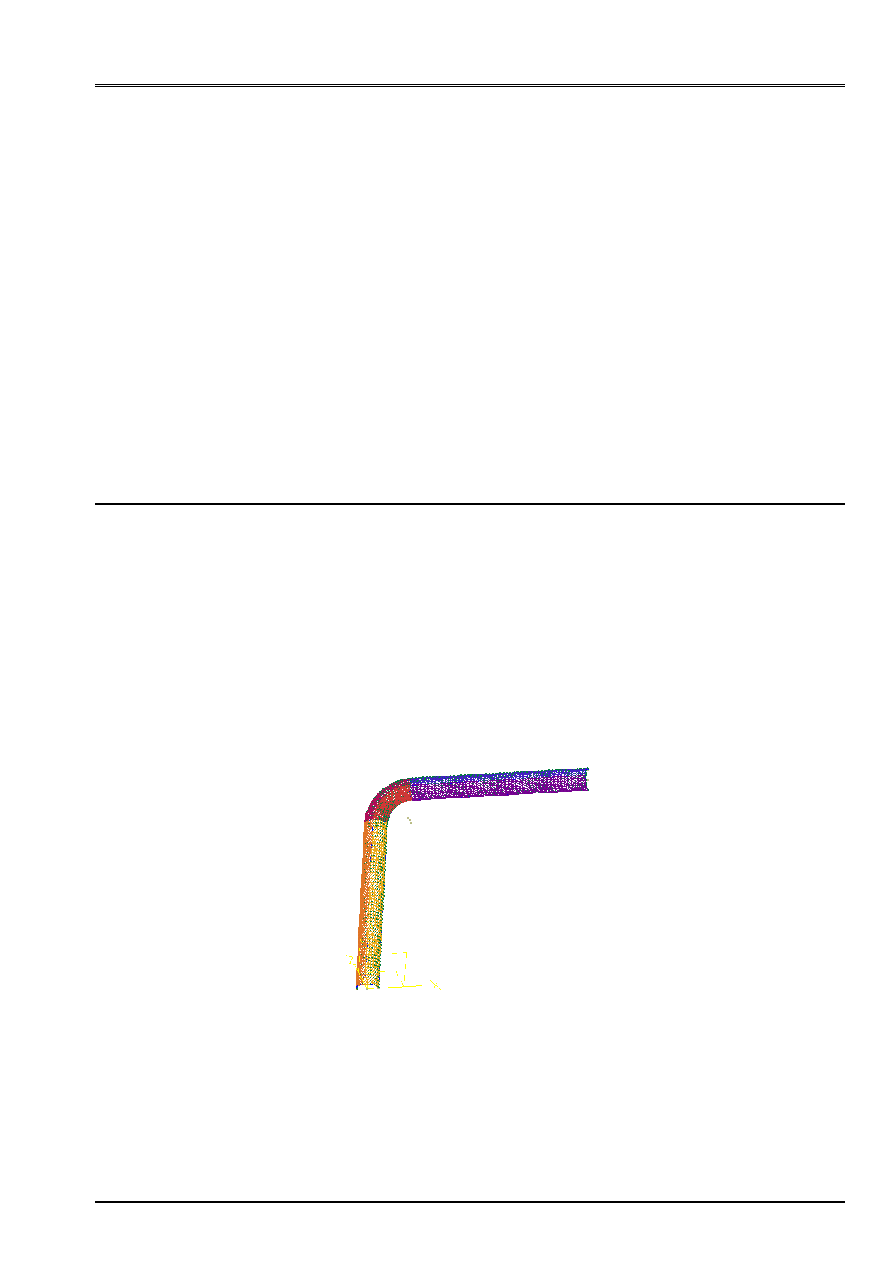
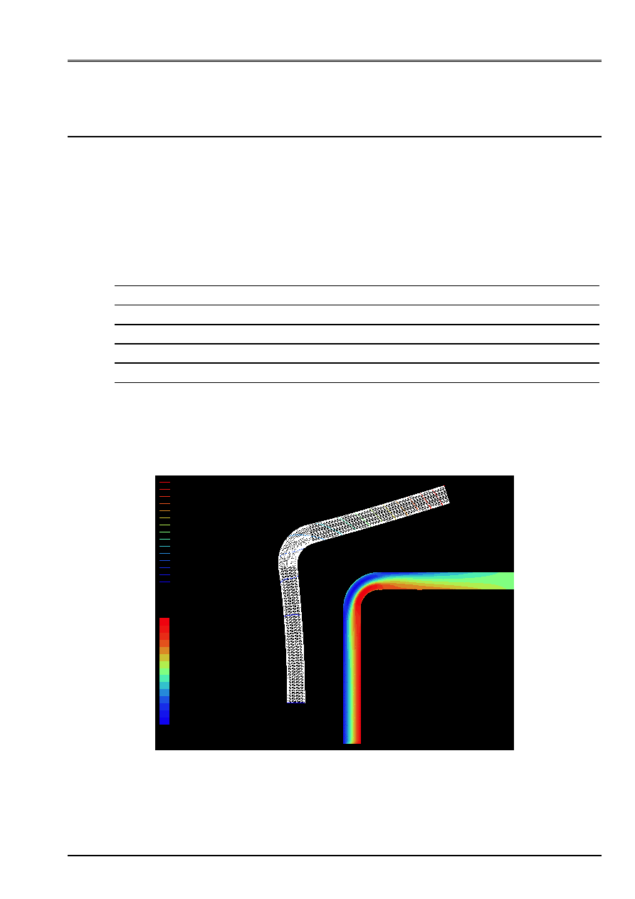
The following graph introduces the deformation and the isovaleurs of axial stresses visualized using
GMSH.
0.000e+00
1.056e-01
DEPL
- 1.719e+08
1.659e+08
SIGM_ELNO_DEPL_SIYY

Code_Aster
®
Version
7.4
Titrate:
An example of use of Code_Aster: calculation of a bent pipe
Date:
18/05/05
Author (S):
Mr. ABBAS, J.M. PROIX
Key
:
U1.05.01-B
Page
:
10/10
Instruction manual
U1.0- booklet: Introduction to Code_Aster
HT-66/05/004/A
Intentionally white left page.