
Code_Aster
®
Version
8.2
Titrate:
Note of use of calculation and postprocessing RCCM
Date:
22/02/06
Author (S):
E. CRYSTAL, J.M. PROIX, Mr. ABBAS
Key
:
U2.09.03-B1
Page:
1/30
Instruction manual
U2.09 booklet: Tools and Solutions Trades
HT-62/06/004/A
Organization (S):
EDF-R & D/AMA
Instruction manual
U2.09 booklet: Tools and Solutions Trades
Document: U2.09.03
Note of use of calculation and postprocessing
of a mechanical study according to the RCCM
Summary:
This document is an aid with the use of postprocessing according to RCCM'S.
Chapter 1 described the postprocessing of fatigue according to the RCCM B3600, i.e. on an analysis of the type
beam of pipings (TYPE_RESU_MECA=' TUYAUTERIE').
Chapters 2 and 3 refer to the postprocessing of fatigue according to the RCCM B3200, following a calculation 2D or
massive 3D of a component or a particular area. Chapter 2 relates to the analysis subjected to
unspecified, mechanical transients or thermics in small number (TYPE_RESU_MECA=' EVOLUTION').
Chapter 3 relates to the analysis of an area of piping subjected to many loadings, resulting from
same situations as the lines of piping of chapter 1 (TYPE_RESU_MECA=' UNITAIRE').

Code_Aster
®
Version
8.2
Titrate:
Note of use of calculation and postprocessing RCCM
Date:
22/02/06
Author (S):
E. CRYSTAL, J.M. PROIX, Mr. ABBAS
Key
:
U2.09.03-B1
Page:
2/30
Instruction manual
U2.09 booklet: Tools and Solutions Trades
HT-62/06/004/A
Count
matters
1
Lawful analysis of a line of piping using POST_RCCM option FATIGUE_B3600….3
1.1
Data available ....................................................................................................................... 3
1.2
Mesh to envisage ........................................................................................................................... 7
1.3
Mechanical calculations ......................................................................................................................... 7
1.3.1
Characteristics of the materials .............................................................................................. 7
1.3.2
Elementary characteristics ................................................................................................ 8
1.3.3
Loadings and boundary conditions .................................................................................. 8
1.3.3.1
Boundary conditions common ............................................................................. 8
1.3.3.2
Definitions of the loadings ...................................................................................... 9
1.3.4
Static calculations .................................................................................................................... 9
1.3.5
Seismic calculations ................................................................................................................... 9
1.3.5.1
Modal calculation ............................................................................................................ 10
1.3.5.2
Inertial answer .................................................................................................... 10
1.4
Thermal calculations ........................................................................................................................ 11
1.4.1
Thermal characteristics ................................................................................................. 11
1.4.2
Calculations of the transients ........................................................................................................ 11
1.4.3
Extraction of the results ........................................................................................................ 12
1.5
Post processing following the RCCM .................................................................................................. 12
2
Complete detailed calculation of an unspecified component and analyzes lawful B3200 using
POST_RCCM .......................................................................................................................................... 15
2.1
Calculation of the component ..................................................................................................................... 15
2.2
Definition of the segments and extraction of the stresses .................................................................. 15
2.3
Calculation of the various criteria using POST_RCCM ................................................................... 16
2.3.1
Option PM_PB ....................................................................................................................... 16
2.3.2
Option SN .............................................................................................................................. 17
2.3.2.1
Sn calculation * ........................................................................................................... 17
2.3.3
Option
FATIGUE_ZH210
...................................................................................................... 18
2.4
Description of the produced tables ................................................................................................... 19
2.4.1
Option
PM_PB
....................................................................................................................... 19
2.4.2
Option
SN
.............................................................................................................................. 19
2.4.3
Option TIRES ................................................................................................................... 20
3
Lawful study of a particular area of a component subjected to many chargements.21
3.1
Definition of the area of analysis ...................................................................................................... 21
3.2
Preliminary calculation of the efforts in extreme cases of the area of analysis ................................................... 22
3.3
Characteristics of the materials ..................................................................................................... 22
3.4
Elementary characteristics of the discrete or linear elements .............................................. 23
3.5
Boundary conditions for the calculation of the unit loadings .................................................. 23
3.6
Static calculations ............................................................................................................................ 24
3.7
Recordings of the stresses ................................................................................................................ 24
3.8
Thermomechanical calculations ........................................................................................................... 25
3.9
POST_RCCM on each segment ........................................................................................ 26
3.10
Description of the produced tables .......................................................................................... 29
4
Bibliography ........................................................................................................................................ 30

Code_Aster
®
Version
8.2
Titrate:
Note of use of calculation and postprocessing RCCM
Date:
22/02/06
Author (S):
E. CRYSTAL, J.M. PROIX, Mr. ABBAS
Key
:
U2.09.03-B1
Page:
3/30
Instruction manual
U2.09 booklet: Tools and Solutions Trades
HT-62/06/004/A
1
Lawful analysis of a line of piping using
POST_RCCM option FATIGUE_B3600
The goal of this chapter is to provide the indication to carry out of A to Z a calculation of a line of
piping subjected to the whole of the loadings envisaged to its design, and its analysis
lawful compared to the damage of fatigue according to the RCC-M B3600.
We will take for example line VVP studied in [bib1]. The aforementioned been the subject of test RCCM02
[V3.01.113] with regard to the analysis with fatigue according to RCC-M B3600. This control is
described in the documentation of use [U4.83.11]. The detail of the equations and criteria is given
in the reference material [R7.04.03].
1.1 Data
available
For a line of piping given, one generally lays out:
·
telegraphic geometry of the line,
·
geometrical characteristics of the various sections of piping, and components
(transitions from thicknesses, elbows, prickings, connections with large components),
·
loadings (mechanical and transients thermal) which must undergo the line during
its operation,
·
materials composing the line (characteristics function of the temperature).
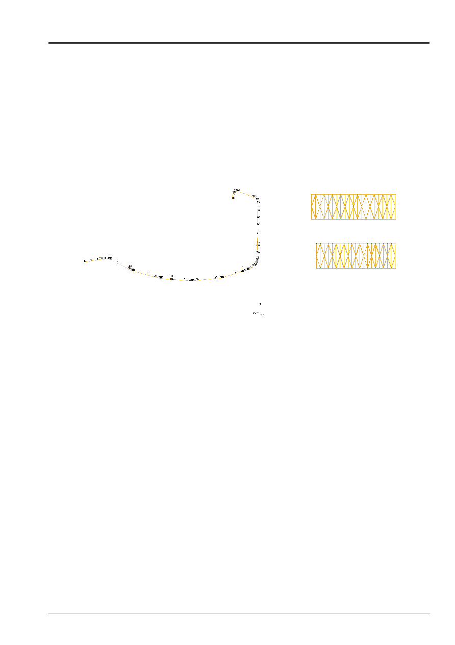
Example (drawn from test RCCM02 [V3.01.113]): data of modeling of line VVP:
The line comprises 10 elbows. It is directed since node NGV until node NBR
Elementary characteristics:
Right parts:
·
R= 406.4 mm, EP=32.mm
·
Pipe Steam Generator, R = 410.mm, EP = 38.mm;
·
Exit Br, R = 444.4mm, EP = 70.mm;
Elbows:
·
Group meshs corresponding to the elbows: R = 406.4mm; EP = 34.mm;
·
Coefficient of flexibility for all the elbows, cflex = 6.032;
·
Radii of bending of the elbows: 1220mm
NGV
NBR

Code_Aster
®
Version
8.2
Titrate:
Note of use of calculation and postprocessing RCCM
Date:
22/02/06
Author (S):
E. CRYSTAL, J.M. PROIX, Mr. ABBAS
Key
:
U2.09.03-B1
Page:
4/30
Instruction manual
U2.09 booklet: Tools and Solutions Trades
HT-62/06/004/A
Moreover for seismic calculation, 6 discrete elements (DIS_T) are added in 3 points of the line
(1 vertical DAB and horizontal by point of anchoring). They have as stiffnesses:
K1= 0.5 10
8
NR/m
K2= 1.0 10
8
NR/m
Characteristics of materials
Line VVP is out of A48 steel. Calculations of the efforts are carried out with various values of
temperature. One thus considers the properties of materials according to the temperature:
Temperature (°C) Modulus Young (GPa) average Expansion factor (from 20°C)
0.0 205
1.092e-05
20.0 204
1.092e-05
50.0 203
1.114e-05
100.0 200
1.15e-05
150.0 197
1.187e-05
200.0 193
1.224e-05
250.0 189
1.257e-05
300.0 185
1.289e-05
350.0 180
1.324e-05
Poisson's ratio: 0.3
The characteristics used for L `analyzes with fatigue according to RCC-M'S are:
m=3
n=0.2
Sm=133.6 MPa
The curve of WOHLER is defined by: (interpolation logarithmic curve):
Salt (Mpa)
A number of cycles
0.01 1.E15
86 1000000
93 500000
114 200000
138 100000
160 50000
215 20000
260 10000
330 5000
440 2000
570 1000
725 500
1070 200
1410 100
1900 50
2830 20
4000 10
The densities integrate heat insulation:
Density (kg/m3)
Blank line
Full line
Current part
8706.3
14200.0
Exit Br
7850.
10295.7
Pipe Steam Generator
8548.0
13500

Code_Aster
®
Version
8.2
Titrate:
Note of use of calculation and postprocessing RCCM
Date:
22/02/06
Author (S):
E. CRYSTAL, J.M. PROIX, Mr. ABBAS
Key
:
U2.09.03-B1
Page:
5/30
Instruction manual
U2.09 booklet: Tools and Solutions Trades
HT-62/06/004/A
The thermal characteristics are provided to the average temperature of the calculated transient:
Transient 2: average temperature = 273.5°C,
Transient 6: average temperature = 281°C,
Temperature °C
273.5
281
Thermal conductivity (W/m.°C)
46.595
46.37
Heat-storage capacity (J/m3.°C)
4.25 10
6
4.27
10
6
Boundary conditions and loadings
The various elementary mechanical loadings considered constitute the stabilized states
corresponding to the situations of design of line VVP:
Loadings of thermal dilation:
One carries out a calculation by loading, which combines the efforts of thermal dilation opposed in
the line at the prescribed temperature, those caused by displacement of the Steam Generator:
Number of
loading
Temperature °C
Ux Steam Generator (mm)
Uy Steam Generator (mm)
Uz Steam Generator (mm)
1
10
0
0
0
2 287
0.046466
0.0304945
0.076
3 274.5
0.046466
0.0304945
0.072
4 272.5
0.046466
0.0304945
0.072
5 286
0.046466
0.0304945
0.076
6 275
0.046466
0.0304945
0.072
7 290
0.046466
0.0304945
0.077
8 284
0.046466
0.0304945
0.077
10 256
0.0360129
0.0245167
0.067
12 257
0.0360129
0.0245167
0.067
14 (test
hydraulics)
20
0
0
0
Boundary conditions: for all the preceding loadings node NBR is embedded.
Moreover, for the hydraulic test ends NGV and NBR are locked and of the supports weight are
additions for this loading: they are modelized by a condition DZ=0, applied in 7 nodes.
Seism: the spectra of floor corresponding to SNA (seism considered for fatigue) are:
Frequency (Hz)
Acceleration (G)
Spectrum of horizontal floor (SNA)
1.0 0.18
2.2 1.56
3.0 1.56
10.0 0.513
20.0 0.281
25.0 0.245
50.0 0.245
Frequency (Hz)
Acceleration (G)
Spectrum of vertical floor
1.0 0.11
2.0 0.21
3.0 0.265
4.0 0.31
6.4 0.31
9.0 0.21
10.0 0.17
25.0 0.1
50.0 0.1

Code_Aster
®
Version
8.2
Titrate:
Note of use of calculation and postprocessing RCCM
Date:
22/02/06
Author (S):
E. CRYSTAL, J.M. PROIX, Mr. ABBAS
Key
:
U2.09.03-B1
Page:
6/30
Instruction manual
U2.09 booklet: Tools and Solutions Trades
HT-62/06/004/A
Associated displacements of anchoring are:
·
node NBR: Dx=4mm, Dy=7mm, Dz=5mm,
·
node NGV: Dx=11.9mm, Dy=mm, Dz=1mm.
Definition of the situations:
Situation Designation
Numbers
occurrences
Pressure
(Bar)
Number of
loading
Transient
thermics
1
Passage cold Stop
nominal operation
190 1
71.5
1
2
-
2
Fluctuations in mode
permanent
1300000 58.9
57.6
3
4
2
3
Hold level Steam Generator
4000
70
59
5
6
6
4
Fluctuations year stop with
heat
100000 73.4
68.1
7
8
2
5
Wrap situations
normals
16080 71.5
44
9
10
6
6
Wrap situations
disturbed
790 74.5
44
11
12
6
7 Seism
SNA
10
390 under-cycles
- Seism -
11 Test
hydraulics
13
112
1
14 -
Thermal transients: two transients “wraps” of the whole of the transients are
calculated. It correspond to a condition of exchange in internal skin of axisymmetric calculation definite
by a coefficient of exchange H=30000W/m2.°C and two stories of temperatures fluid:
Transient 2
Transient 6
Time (S)
Fluid temperature (°C)
Time (S)
Fluid temperature (°C)
0.0 274.5 0.0 272.0
10.0 274.5
11.0 272.0
310.0 272.5
20.0 290.0
610.0 274.5
40.0 290.0
910.0 272.5
Code_Aster
®
Version
8.2
Titrate:
Note of use of calculation and postprocessing RCCM
Date:
22/02/06
Author (S):
E. CRYSTAL, J.M. PROIX, Mr. ABBAS
Key
:
U2.09.03-B1
Page:
7/30
Instruction manual
U2.09 booklet: Tools and Solutions Trades
HT-62/06/004/A
1.2
Mesh to be envisaged
Two types of mesh must be made up:
·
mesh of the line, in telegraphic elements (meshs SEG2),
·
a mesh corresponding to each particular type of geometry for the transients
thermics.
For example for the telegraphic mesh, the elbows are discretized each one in 4 elements.
The meshs composing the elbow will be associated modeling POU_C_T. Right parts
will be affected modeling POU_D_T.
Notice on the discretization: with regard to the static loadings, the discretization in
elements POU_D_T does not need to be fine to provide precise solutions [R3.08.01]. By
against for the dynamic analysis, to be able to obtain high clean modes with a precision
sufficient, it is necessary to discretize more finely. For example, 4 elements per right part are
generally sufficient for the first 10 Eigen frequencies.
With regard to the mesh used for thermal calculations, it will be necessary to take care to net
finely in the direction of the conduction of heat. For example, partly current of piping,
the mesh is a section of tube, modelized into axisymmetric. Only one element is enough in the direction
axial. The 2 mesh above corresponds to the two thicknesses characteristic of the line.
For modeling, it is preferable (to obtain a correct solution) to use modelings
with diagonalized thermal mass (AXIS_DIAG, 3d_DIAG).
1.3 Calculations
mechanics
1.3.1 Characteristics of materials
The elastic characteristics are to be provided according to the temperature (to take care to define a range
of sufficiently broad temperature to cover the whole of the thermal conditions seen by
line. This is preferable with the definition of the prolongations which can lead to aberrations). One
can use the catalog material which gathers in particular the characteristics of all them
materials of the RCCM.
For seismic calculations, it is necessary to add the density (integrating the weight of the water and of
heat insulator). It is also necessary to introduce the characteristics of fatigue: coefficients N and m for
calculation of Ke, and curve of Wöhler. It is preferable for the latter (being given its definition)
to define an interpolation logarithmic curve).

Code_Aster
®
Version
8.2
Titrate:
Note of use of calculation and postprocessing RCCM
Date:
22/02/06
Author (S):
E. CRYSTAL, J.M. PROIX, Mr. ABBAS
Key
:
U2.09.03-B1
Page:
8/30
Instruction manual
U2.09 booklet: Tools and Solutions Trades
HT-62/06/004/A
For example, the data material for line VVP are:
YOUNG=DEFI_FONCTION (NOM_PARA=' TEMP',
VALE= (20.0, 204000000000.0, 50.0, 203000000000.0, 100.0, 200000000000.0,…),);
C_ALPHA=DEFI_FONCTION (NOM_PARA=' TEMP',
VALE= (20.0, 1.092e-05,50.0, 1.114e-05,100.0, 1.15e-05,…,),);
NU=DEFI_CONSTANTE (VALE=0.3,);
# CURVED OF A48 FATIGUE (one defines Nadm according to Salt)
WOHLER=DEFI_FONCTION (NOM_PARA=' SIGM',
VALE= (86000000.0, 1000000.0,
93000000.0, 500000.0,
114000000.0, 200000.0,
138000000.0, 100000.0,
160000000.0, 50000.0,
.......
INTERPOL=' LOG',);
RHOV = 8706.3;
MAT_A48V=DEFI_MATERIAU (ELAS_FO=_F (E=YOUNG, NU=NU,
RHO=RHOV,
TEMP_DEF_ALPHA=20.0,
ALPHA=C_ALPHA,),
FATIGUE=_F (WOHLER=WOHLER, E_REFE=2.07E11,),
RCCM=_F (SM=1.336E8,
N_KE=0.2,
M_KE=3.0,),);
1.3.2 Characteristics
elementary
They are entirely defined by AFFE_CARA_ELEM. With regard to the elbows, it is more
practical in AFFE_CARA_ELEM to provide the orientations of the arcs using CENTER or
POIN_TANG. One can check (INFO=2) that radii of curvature recomputed by Aster
correspond well to the radii of the elbows. It is necessary to define the coefficients of flexibility
(definite for example in RCC-M B3600 [bib2]) agent with each elbow. For example:
CARA_POU=AFFE_CARA_ELEM (MODELE=MODELE, INFO=2,
POUTRE= (_F (GROUP_MA=' TUYAU', SECTION=' CERCLE',
CARA= (“R”, “EP”,), VALE= (RTUB, EPTUB,),),
_F (GROUP_MA=' L1', SECTION=' CERCLE',
CARA= (“R”, “EP”,), VALE= (RGV, EPGV,),),
….
DEFI_ARC= (_F (GROUP_MA=' C3', CENTER= (10.62, - 4.9, 30.78,), COEF_FLEX=C_FLEX,),
_F (GROUP_MA=' C7', CENTER= (…
DISCRET= (_F (GROUP_MA=' RIG1', CARA=' K_T_D_L', VALE= (0.0, 0.0, 0.0,),),
_F (GROUP_MA=' RIG2',….
1.3.3 Loadings and boundary conditions
1.3.3.1 Boundary conditions common
In general there are boundary conditions common to all the loadings (for example one
embedding corresponding to the passage of the line by a fixed point). For example:
BLOCBR=AFFE_CHAR_MECA (MODELE=MODELE,
DDL_IMPO= (_F (GROUP_NO=' NBR',
DX=0.0,
DY=0.0,
DZ=0.0,
DRX=0.0,
DRY=0.0,
DRZ=0.0,),

Code_Aster
®
Version
8.2
Titrate:
Note of use of calculation and postprocessing RCCM
Date:
22/02/06
Author (S):
E. CRYSTAL, J.M. PROIX, Mr. ABBAS
Key
:
U2.09.03-B1
Page:
9/30
Instruction manual
U2.09 booklet: Tools and Solutions Trades
HT-62/06/004/A
1.3.3.2 Definitions of the loadings
The stabilized states defining the situations are in general the combination of loadings
purely mechanical (actual weight, displacement imposed by a component in one or more
points of the circuit) and thermal dilations (one does not consider the thermal transient here but
only efforts due to the opposed dilation of the line for each state stabilized of each
situation). This requires to define constant fields of temperature by areas or for all
line, using CREA_CHAMP. For example, the state stabilized number 5 is entirely defined by
following loadings:
CHAR1=AFFE_CHAR_MECA (MODELE=MODELE,
DDL_IMPO=_F (GROUP_NO=' NGV',
DX=0.046466,
DY=-0.0304945,
DZ=0.076,
DRX=0.0,
DRY=0.0,
DRZ=0.0,),);
TEMP286=CREA_CHAMP (TYPE_CHAM=' NOEU_TEMP_R',
OPERATION=' AFFE', MAILLAGE=MAILL,
AFFE=_F (TOUT=' OUI', NOM_CMP=' TEMP', VALE=286.0,),);
CHT286=AFFE_CHAR_MECA (MODELE=MODELE,
TEMP_CALCULEE=TEMP286,);
1.3.4 Calculations
statics
A calculation (using MECA_STATIQUE) is to be carried out for each stabilized state, by adding calculation
efforts in option of calculation. Here for the loading number 5:
RMECA5=MECA_STATIQUE (MODELE=MODELE, CHAM_MATER=CHAMPMAV, CARA_ELEM=CARA_POU,
EXCIT= (_F (CHARGE=BLOCBR,),
_F (CHARGE=CHT286,),
_F (CHARGE=CHAR1,),),
OPTION=' EFGE_ELNO_DEPL',);
1.3.5 Calculations
seismic
Seismic calculations are composed of inertial calculations, and static calculations of displacements
anchorings. The latter are similar to static calculations previously described. One must carry out
a calculation by component of displacement for each anchoring. For example, in the case of the line
VVP, one needs a calculation for each component of displacement imposed on node NBR, and of
even on node NGV:
ANC_BRDX=AFFE_CHAR_MECA (MODELE=MODELE,
DDL_IMPO=_F (GROUP_NO=' NBR',
DX=4.0E-3, DY=0.0, DZ=0.0,
DRX=0.0, DRY=0.0, DRZ=0.0,),);
RANCBRDX=MECA_STATIQUE (MODELE=MODELE, CHAM_MATER=CHAMPMAV,
CARA_ELEM=CARA_POU,
EXCIT= (_F (CHARGE=BLOCGV,),
_F (CHARGE=CHT20,),
_F (CHARGE=ANC_BRDX,),),
OPTION=' EFGE_ELNO_DEPL',);
The calculation of the inertial answer requires several stages:

Code_Aster
®
Version
8.2
Titrate:
Note of use of calculation and postprocessing RCCM
Date:
22/02/06
Author (S):
E. CRYSTAL, J.M. PROIX, Mr. ABBAS
Key
:
U2.09.03-B1
Page:
10/30
Instruction manual
U2.09 booklet: Tools and Solutions Trades
HT-62/06/004/A
1.3.5.1 Calculation
modal
That can be easily carried out using MACRO_MATR_ASSE and MODE_ITER_SIMULT. It is necessary
to take care to take into account sufficient clean modes (here 11). Here modal calculation is carried out
with the line full of water (modified densities) and the locked DAB.
MACRO_MATR_ASSE (MODELE=MODELE,
CHAM_MATER=CHAMPMAV,
CARA_ELEM=CARA_DAB,
CHARGE= (CHT287, BLOCGVBR,),
NUME_DDL=CO (“NUME”),
MATR_ASSE= (_F (MATRICE=CO (“RIGIDITY”), OPTION=' RIGI_MECA',),
_F (MATRICE=CO (“MASS”), OPTION=' MASS_MECA',),));
TABL_MAS=POST_ELEM (MASS_INER=_F (TOUT=' OUI',), MODELE=MODELE,
CHAM_MATER=CHAMPMAV, CARA_ELEM=CARA_DAB,);
MODE_MEC=MODE_ITER_SIMULT (MATR_A=RIGIDITE, MATR_B=MASSE,
CALC_FREQ=_F (OPTION=' PLUS_PETITE', NMAX_FREQ=11),);
MODE_MEC=CALC_ELEM (reuse =MODE_MEC, MODELE=MODELE,
CHAM_MATER=CHAMPMAV, CARA_ELEM=CARA_DAB,
OPTION=' EFGE_ELNO_DEPL', RESULTAT=MODE_MEC,
EXCIT= (_F (CHARGE=BLOCGVBR,),
_F (CHARGE= CHT287,),),);
1.3.5.2 Answer
inertial
It is necessary to define the spectra of accélérogrammes imposed on the supports. The horizontal spectrum is different
vertical spectrum in the selected example: (attention with the units chosen for acceleration: here
COMB_SISM_MODAL awaits accelerations in “G” cf key word SCALE of COMB_SISM_MODAL):
ACCE_XY=DEFI_FONCTION (NOM_PARA=' FREQ',
VALE= (1.0, 0.18, 2.2, 1.56, 3.0, 1.56,…),
INTERPOL=' LOG', PROL_DROITE=' CONSTANT', PROL_GAUCHE=' CONSTANT',);
ACCE_Z=DEFI_FONCTION (NOM_PARA=' FREQ',
VALE= (1.0, 0.11, 2.0, 0.21, 3.0, 0.265,…),
INTERPOL=' LOG', PROL_DROITE=' CONSTANT', PROL_GAUCHE=' CONSTANT',);
SPECT_XY=DEFI_NAPPE (NOM_PARA=' AMOR', PARA= (0.015, 0.02, 0.025,),
FONCTION= (ACCE_XY, ACCE_XY, ACCE_XY,),
INTERPOL= (“FLAX”, “LOG”,),);
SPECT_Z=DEFI_NAPPE (NOM_PARA=' AMOR', PARA= (0.015, 0.02, 0.025,),
FONCTION= (ACCE_Z, ACCE_Z, ACCE_Z,),
INTERPOL= (“FLAX”, “LOG”,),);
MODE_STA=MODE_STATIQUE (MATR_RIGI=RIGIDITE, MATR_MASS=MASSE,
PSEUDO_MODE=_F (AXE= (“X”, “Y”, “Z”,),),);
MODE_STA=CALC_ELEM (reuse =MODE_STA, MODELE=MODELE, CHAM_MATER=CHAMPMAV,
CARA_ELEM=CARA_DAB, OPTION=' EFGE_ELNO_DEPL',
RESULTAT=MODE_STA, EXCIT= (...)
SISM_SPE=COMB_SISM_MODAL (MODE_MECA=MODE_MEC, MODE_CORR=MODE_STA,
AMOR_REDUIT=0.02, MASS_INER=TABL_MAS,
CORR_FREQ=' NON',
EXCIT=_F (MONO_APPUI=' OUI',
TRI_SPEC=' OUI',
SPEC_OSCI= (SPECT_XY, SPECT_XY, SPECT_Z,),
ECHELLE= (9.81, 9.81, 9.81,),),
COMB_MODE=_F (TYPE=' SRSS',),
COMB_DIRECTION=_F (TYPE=' QUAD',),
OPTION= (“DEPL”, “EFGE_ELNO_DEPL”,),);

Code_Aster
®
Version
8.2
Titrate:
Note of use of calculation and postprocessing RCCM
Date:
22/02/06
Author (S):
E. CRYSTAL, J.M. PROIX, Mr. ABBAS
Key
:
U2.09.03-B1
Page:
11/30
Instruction manual
U2.09 booklet: Tools and Solutions Trades
HT-62/06/004/A
1.4 Calculations
thermics
The purpose of transitory thermal calculations are, in the case of the RCCM B3600, to evaluate the gradients
of maximum temperature during transients, in each part of the line. For the parts
current to pipings, in theory, a thermal calculation of conduction 1D would be enough. In practice, one
will be able to carry out an axisymmetric calculation of a section of tube (the axial length with a grid not having
no importance). For the more complex areas, it can be necessary to carry out a mesh
2D or precise 3D of the area.
To reduce the command files, it can be useful to build each thermal modeling
in a clean file, which will be included (control INCLUDE) in the main command file
at the object time.
1.4.1 Characteristics
thermics
They can be extracted from the catalog MATERIAL of Code_Aster. They can be a function of
temperature (in which case will have to be carried out a nonlinear thermal calculation), or interpolated with
average temperature of each transient to be calculated (practical current, but to validate in all
rigor). For example, for each of the 2 transients of line VVP:
# COEFS AVERAGE OF COEFF A 273.5
MATHER=DEFI_MATERIAU (THER=_F (LAMBDA=46.595, RHO_CP=4.25E6,),);
CHMAT=AFFE_MATERIAU (MAILLAGE=MA,
AFFE=_F (TOUT=' OUI', MATER=MATHER,),);
# COEFS AVERAGE OF COEFF A 281
MATHER2=DEFI_MATERIAU (THER=_F (LAMBDA=46.37, RHO_CP=4.27E6,),);
CHMAT2=AFFE_MATERIAU (MAILLAGE=MA,
AFFE=_F (TOUT=' OUI', MATER=MATHER2,),);
1.4.2 Calculations of the transients
They are often characterized by a history of temperature in internal skin of piping
(fluid temperature) and a coefficient of exchange. It will have to be taken care that the temporal discretization
that is to say sufficiently fine for good “to collect” the variations in temperature (to carry out several tests).
COEFH=DEFI_CONSTANTE (VALE=3.E4,);
TR2=DEFI_FONCTION (NOM_PARA=' INST', VALE= (0.0, 274., 10.0, 274., 310.0, 272….),);
CHTH2=AFFE_CHAR_THER_F (MODELE=MOTHER,
ECHANGE=_F (GROUP_MA= (“ECHAND”, “ECHANC”,),
COEF_H=COEFH, TEMP_EXT=TR2,),);
LISTH2=DEFI_LIST_REEL (DEBUT=0.0,
INTERVALLE= (_F (JUSQU_A=10.0, PAS=10.0,),
_F (JUSQU_A=310.0, PAS=10.0,), _…,),);
TEMP2=THER_LINEAIRE (SOLVEUR=_F (RENUM=' MDA'), MODELE=MOTHER,
CHAM_MATER=CHMAT, EXCIT=_F (CHARGE=CHTH2,),
INCREMENT=_F (LIST_INST=LISTH2,),
TEMP_INIT=_F (VALE=274.5,),);

Code_Aster
®
Version
8.2
Titrate:
Note of use of calculation and postprocessing RCCM
Date:
22/02/06
Author (S):
E. CRYSTAL, J.M. PROIX, Mr. ABBAS
Key
:
U2.09.03-B1
Page:
12/30
Instruction manual
U2.09 booklet: Tools and Solutions Trades
HT-62/06/004/A
1.4.3 Extraction of the results
For the analysis with POST_RCCM, it is necessary to extract the values and the average temperatures,
for every moment calculated, on a segment defined by INTE_MAIL_2D (or a group of nodes,
reorientated using DEFI_GROUP, OPTION = ' SEGM_DROI_ORDO') energy of the skin interns towards
external skin. For example:
TABTH 2D=POST_RELEVE_T (ACTION=_F (INTITULE=' TEMP2', GROUP_NO=' BASD',
RESULTAT=TEMP2, NOM_CHAM=' TEMP', NOM_CMP=' TEMP',
OPERATION=' EXTRACTION',),);
TABMO 2D=POST_RELEVE_T (ACTION=_F (INTITULE=' TEMP2', GROUP_NO=' BASD',
RESULTAT=TEMP2, NOM_CHAM=' TEMP', NOM_CMP=' TEMP',
OPERATION=' MOYENNE',),);
1.5
Post processing following the RCCM
It any more but does not remain to call POST_RCCM with the B3600 option, while providing [U4.83.11]:
·
geometry of the line of piping,
·
the material field: it is the card of materials assigned to the groups of meshs of
mesh by AFFE_MATERIAU for which it is necessary to add the curve of fatigue, E_REFE, m and N
(key words RCCM),
·
AFFE_CARA_ELEM makes it possible to affect the elementary characteristics,
·
indices of stresses (in each node of the mesh),
·
the scenario of operation containing the list of the situations:
- for each situation:
- numbers of occurrences of each situation (thus of each stabilized state),
- pressure and average temperature of each stabilized state,
- list of the mechanical loadings (characterized by a number) of each state
stabilized,
- the group of membership of the situation,
- the associated thermal transient,
·
results of calculations for each mechanical loading (including the seism), (identified
by its number, with for information the name of the loading case): field by elements with the nodes
generalized efforts, for each loading (EFGE_ELNO_DEPL, or SIEF_ELNO_ELGA),
·
for each node, a reference to a definite thermal result below,
·
results of thermal calculations: calculations EFF 2D or 3D which give these infos
depend at the same time on the geometry and transient. There is thus a thermal calculation by type
of junction, and by type of transient.
To complete the example of line VVP, the call to POST_RCCM is as follows (INFO=2 allows to obtain
details of calculations):
TBRCCM1=POST_RCCM (
OPTION=' FATIGUE_B3600', INFO=2,
CHAM_MATER=CHAMPMAV, MODELE=MODELE, CARA_ELEM=CARA_POU,
# area of analysis
ZONE_ANALYZE=_F (MESH = (“M1”, “M2”),),
# results mechanical (calculated with MECA_STATIQUE)
RESU_MECA= (
_F (NUME_CHAR=1,
NOM_CHAR=' STATE 1 SITUATION 1 ',
TOUT_ORDRE=' OUI', RESULTAT=RMECA1,
NOM_CHAM=' EFGE_ELNO_DEPL',),
_F (NUME_CHAR=2,
NOM_CHAR=' STATE 2 SITUATION 1 ',
TOUT_ORDRE=' OUI', RESULTAT=RMECA2_9,
NOM_CHAM=' EFGE_ELNO_DEPL',),
......

Code_Aster
®
Version
8.2
Titrate:
Note of use of calculation and postprocessing RCCM
Date:
22/02/06
Author (S):
E. CRYSTAL, J.M. PROIX, Mr. ABBAS
Key
:
U2.09.03-B1
Page:
13/30
Instruction manual
U2.09 booklet: Tools and Solutions Trades
HT-62/06/004/A
# Seism inertial answer (COMB_SISM_MODAL)
_F (NUME_CHAR=1000,
NOM_CHAR=' SNA',
TYPE_CHAR=' SEISME',
RESULTAT=SISM_SPE,
NOEUD_CMP= (“COMBI”, “QUAD”,),
NOM_CHAM=' EFGE_ELNO_DEPL',),
# displacement of anchoring on the level left Br following DX
_F (NUME_CHAR=1001,
NOM_CHAR=' SNA DEPL ANC BR DX',
TYPE_CHAR=' SEISME',
TOUT_ORDRE=' OUI', RESULTAT=RANCBRDX,
NOM_CHAM=' EFGE_ELNO_DEPL',),
….
),
# indices of stresses
INDI_SIGM= (
_F (TOUT=' OUI', TYPE_ELEM_STANDARD=' DRO',),
_F (C1=1.0,
K1=1.10,
C2=1.0,
K2=1.10,
C3=0.60,
K3=1.10,
MAILLE= (“M1”), NOEUD= (“N79”),
TYPE_ELEM_STANDARD=' COU',),
…
),
# results thermal
RESU_THER= (
# results on the right tubes transient 2
_F (NUME_RESU_THER=12,
TABL_RESU_THER=TABTH 2D,
TABL_MOYE_THER=TABMO 2D,
GROUP_MA=' POUDT',),
# results on the right tubes transient 6
_F (NUME_RESU_THER=16,
TABL_RESU_THER=TABTH6D,
TABL_MOYE_THER=TABMO6D,
GROUP_MA=' POUDT',),
# results on the elbows transient 2
_F (NUME_RESU_THER=22,
TABL_RESU_THER=TABTH2C,
TABL_MOYE_THER=TABMO2C,
GROUP_MA=' POUCT',),
# results on the elbows transient 6
_F (NUME_RESU_THER=26,
TABL_RESU_THER=TABTH6C,
TABL_MOYE_THER=TABMO6C,
GROUP_MA=' POUCT',),
),
# situations
SITUATION= (
_F (NB_OCCUR=190, NUME_SITU=1,
NOM_SITU=' Passage cold stop
operation nominal',
NUME_GROUPE=1,
PRES_A=1.0E5,
PRES_B=71.5E5,
TEMP_REF_A=10.0,
TEMP_REF_B=287.0,
CHAR_ETAT_A=1,
CHAR_ETAT_B=2,),

Code_Aster
®
Version
8.2
Titrate:
Note of use of calculation and postprocessing RCCM
Date:
22/02/06
Author (S):
E. CRYSTAL, J.M. PROIX, Mr. ABBAS
Key
:
U2.09.03-B1
Page:
14/30
Instruction manual
U2.09 booklet: Tools and Solutions Trades
HT-62/06/004/A
_F (NB_OCCUR=1300000, NUME_SITU=2,
NOM_SITU=' fluctuations in mode permanent',
NUME_GROUPE=1,
PRES_A=58.9E5,
PRES_B=57.6E5,
TEMP_REF_A=274.5,
TEMP_REF_B=272.5,
CHAR_ETAT_A=3,
CHAR_ETAT_B=4,
NUME_RESU_THER= (12,22),),
_F (NB_OCCUR=10,
NB_CYCL_SEISM=390,
NUME_SITU=7,
NOM_SITU=' Seism SNA',
COMBINABLE=' OUI',
NUME_GROUPE=1,
CHAR_ETAT_A= (1000,1001,1002,1003,1004,1005,1006),),
_F (NB_OCCUR=13,
NUME_SITU=11,
NOM_SITU=' Test hydraulique',
# NUME_GROUPE=2,
NUME_GROUPE=1,
PRES_A=112.0E5,
PRES_B=1.0E5,
TEMP_REF_A=20.0,
TEMP_REF_B=10.0,
CHAR_ETAT_A=1,
CHAR_ETAT_B=14,),
),
);
It any more but does not remain to print the produced table:
IMPR_TABLE (TABLE=TBRCCM1,);
One obtains then:
TABL_POST_RCCM
NET TYPE_MAILLE NODE SM SN_MAX SN/3SM SALT_MAX FACT_USAGE_CUMU
M1 DRO N80 1.33600E+08 1.35615E+08 3.38360E-01 7.44376E+07 4.58400E-03
M1 NECK N79 1.33600E+08 1.35207E+08 3.37342E-01 8.15106E+07 5.58793E-03
M2 NECK N79 1.33600E+08 1.50176E+08 3.74690E-01 8.69347E+07 6.30413E-03
M2 DRO N78 1.33600E+08 1.49870E+08 3.73926E-01 8.05593E+07 5.37650E-03

Code_Aster
®
Version
8.2
Titrate:
Note of use of calculation and postprocessing RCCM
Date:
22/02/06
Author (S):
E. CRYSTAL, J.M. PROIX, Mr. ABBAS
Key
:
U2.09.03-B1
Page:
15/30
Instruction manual
U2.09 booklet: Tools and Solutions Trades
HT-62/06/004/A
2
Complete detailed calculation of an unspecified component and
analyze lawful B3200 using POST_RCCM
This type of analysis is justified when one wants to analyze a component subjected to one or with little of
transients (and not of seism), in order to check the various criteria of the RCC-M B3200 (deformation
excessive, progressive deformation, fatigue according to appendix ZH210).
If one wishes to analyze a component with fatigue, for the whole of the situations to which it will be
subjected, and in particular with the seism, it is preferable to use the method described in the following chapter.
This type of analysis functions only for modelings of continuous mediums 2D (D_PLAN, C_PLAN,
AXIS) or 3D.
One will take for example tests RCCM01, and SSLV100.
2.1
Calculation of the component
It is a question here of carrying out the direct calculation of the component, for the loadings which one wants to evaluate
criteria.
To modelize the elbows or prickings, it is convenient to use tools ASCOUF (macros
controls MACR_ASCOUF_MAIL and MACR_ASCOUF_CALC) and ASPIC (MACR_ASPIC_MAIL and
MACR_ASPIC_CALC).
With the exit of these calculations, one has a certain number of concepts results, thermo elastic 2D
or 3D, produced by MECA_STATIQUE or STAT_NON_LINE, and for which one calculated the option
SIGM_ELNO_DEPL (by taking care in CALC_ELEM to provide the load containing them
temperatures) or better: SIEF_ELNO_ELGA (CALC_ELEM).
For example (RCCM01):
RESU2=MECA_STATIQUE (MODELE=MO, CHAM_MATER=CHMAT,
LIST_INST=LINST,
EXCIT= (_F (LOAD = CHTHER),
_F (LOAD = CHMEC, FONC_MULT = FCTMUL)),
OPTION= (“SIGM_ELNO_DEPL”,
)
2.2
Definition of the segments and extraction of the stresses
It is a question of extracting, on each segment studied, the stresses, for each transient. Let us recall
that the criteria of the RCC-M B3200 are to be checked for the whole of the possible segments,
crossing the component of the skin interns to the external skin. The choice of the maximizing segment
the criteria is the responsibility of the user. For a complex geometry, the aforementioned will have to thus calculate
a certain number of segments.
In practice, in Code_Aster, several methods are possible to define the segments of analysis
then to extract the stresses there:
·
the first consists in using the controls INTE_MAIL_2D or INTE_MAIL_3D, according to
geometrical dimension of the problem, to define an unspecified segment passing in through
mesh then to extract the stresses by POST_RELEVE_T:
LIGNE1=INTE_MAIL_2D (MAILLAGE=MA,
DEFI_SEGMENT=_F (ORIGIN = (- 1.0, 0.5,),
END = (1.0, 0.5,)),
INFO=2)

Code_Aster
®
Version
8.2
Titrate:
Note of use of calculation and postprocessing RCCM
Date:
22/02/06
Author (S):
E. CRYSTAL, J.M. PROIX, Mr. ABBAS
Key
:
U2.09.03-B1
Page:
16/30
Instruction manual
U2.09 booklet: Tools and Solutions Trades
HT-62/06/004/A
TAB2=POST_RELEVE_T (ACTION=_F (ENTITLES = “LINE”,
PATH = LIGNE1,
RESULT = RESU2,
NOM_CHAM = “SIGM_ELNO_DEPL”,
OPERATION = “EXTRACTION”,
TOUT_CMP = “YES”,),)
·
the second method consists in using a preexistent group of nodes in the mesh,
defining a segment. This method obligatorily requires to reorder as a preliminary
the group of nodes, so that the nodes the component are arranged skin interns towards
external skin:
MA=DEFI_GROUP (reuse=MA, MAILLAGE=MA,
CREA_GROUP_NO= (_F (OPTION = “SEGM_DROI_ORDO”,
NAME = “LINE”,
GROUP_NO=' GN1',
NOEUD_ORIG = “N22”,
NOEUD_EXTR = “N12”,
PRECISION = 1.E-03,
CRITERION = “RELATIVE”)
TAB2=POST_RELEVE_T (ACTION=_F (ENTITLES = “LINE”,
GROUP_NO = LINE,
RESULT = RESU2,
NOM_CHAM = “SIGM_ELNO_DEPL”,
OPERATION = “EXTRACTION”,
TOUT_CMP = “YES”,),)
·
the last method consists in using macro-control MACR_LIGN_COUPE to define
the segment of analysis starting from its ends and to extract the stresses:
MACR_LIGN_COUPE (RESULTAT=RESU2,
NOM_CHAM=' SIGM_ELNO_DEPL',
MODELE=MO,
LIGN_COUPE=_F (NB_POINTS=5,
COOR_ORIG= (- 1.0, 0.5,),
COOR_EXTR= (1.0, 0.5,),
TABLE=CO (“TAB2”),),)
2.3
Calculation of the various criteria using POST_RCCM
The criteria available are:
·
criteria of level 0 by option PM_PB,
·
criteria of level A (except fatigue) by the option SN,
·
criteria of fatigue (also of level A) by option FATIGUE_ZH210.
2.3.1 Option
PM_PB
Option allowing to calculate the criteria of level 0 which aim at securing the hardware against
damage of excessive deformation, plastic instability and elastic and elastoplastic instability.
These criteria require the calculation of the equivalent stresses of membrane
m
P
, of membrane
local
L
P
, of bending
B
P
and of membrane plus bending
B
m
P
P
+
. The points of calculation are both
ends of the segment of analysis. If several segments of extraction were used to define one
even table of stresses, calculation is done successively for each one of them.

Code_Aster
®
Version
8.2
Titrate:
Note of use of calculation and postprocessing RCCM
Date:
22/02/06
Author (S):
E. CRYSTAL, J.M. PROIX, Mr. ABBAS
Key
:
U2.09.03-B1
Page:
17/30
Instruction manual
U2.09 booklet: Tools and Solutions Trades
HT-62/06/004/A
In each point end of the segment of analysis length L, one calculates:
()
()
()
Pm
Pb
Pm Pb
L
ds
L
S
L
ds
T
ijmoy Eq Tresca
T
ijfle Eq Tresca
T
ijlin Eq Tresca
ijmoy
ij
L
ijfle
ij
L
ijlin
ijmoy
ijfle
=
=
+
=
=
=
-
=
±
max
max
max
,
,
.
.
.
with
1
6
2
0
2 0
The values limit are
m
S
and 1.5
m
S
,
m
S
being working stress function of material and of
the temperature, given by the key word SM of key word RCCM in DEFI_MATERIAU [U4.43.01].
Note:
The calculation of PM and PMPB is only done starting from the primary stresses, therefore out
stresses of thermal origin. If TABL_SIGM_THER is indicated, it is supposed that it
result indicated in TABL_RESU_MECA corresponds to a thermomechanical calculation and one him
thus withdrawn the thermal stresses. If only TABL_RESU_MECA is indicated, calculation
is done directly starting from the stresses indicated in the table.
2.3.2 Option
SN
Option allowing to calculate the criteria of level A (except fatigue) which aim at securing the hardware
against the damage of progressive deformation. They require the calculation of the amplitude of variation
of stress linearized in a point, noted
N
S
.
If the user asks it (presence of operand TABL_SIGM_THER) one also the calculation carries out of
S
N *
. The points of calculation are the two ends of the segment of analysis. If several segments
of extraction were used to define the same table of stresses, calculation is done successively
for each one of them.
In each point end of this segment length L, one calculates:
()
()
(
)
Sn
T
T
L
ds
L
S
L
ds
T
T
ijlin
ijlin
Eq Tresca
ijmoy
ij
L
ijfle
ij
L
ijlin
ijmoy
ijfle
=
-
=
=
-
=
±
max max
,
,
.
1
2
1
2
0
2 0
1
6
2
with
with T1 and t2 traversing the whole of the moments of (or of) transitory. The value limits
N
S
is
m
S
.
3
,
m
S
being the working stress function of material and temperature, given by
key word SM of the key word factor RCCM in DEFI_MATERIAU [U4.43.01].
Note:
Key word TABL_RESU_MECA can be repeated several times under only one key word
TRANSIENT. For the calculation of SN and SN *, there will be however no combination enters
situations thus defined: each table of stresses will be treated successively.
2.3.2.1 Calculation
of
Sn *
If operand TABL_SIGM_THER of the key word factor
T
RANSITOIRE is present, one carries out also it
calculation of
S
N *
who is equal to the amplitude
N
S
calculated without taking into account the stresses of
thermal bending of origin. One calculates for each end:
()
()
(
)
()
()
(
)
(
)
-
=
-
-
-
=
L
HT
ij
fleth
ij
Tresca
Eq
fleth
ij
flax
ij
fleth
ij
flax
ij
T
T
N
ds
L
S
L
T
T
T
T
S
0
2
.
2
2
1
1
*
2
6
max
max
2
1
*

Code_Aster
®
Version
8.2
Titrate:
Note of use of calculation and postprocessing RCCM
Date:
22/02/06
Author (S):
E. CRYSTAL, J.M. PROIX, Mr. ABBAS
Key
:
U2.09.03-B1
Page:
18/30
Instruction manual
U2.09 booklet: Tools and Solutions Trades
HT-62/06/004/A
ijth
coming from the stresses provided in
TABL_SIGM_THER
.
It is necessary, so that calculation is coherent and in conformity with the RCC-M, that stresses provided in
TABL_SIGM_THER
were obtained with a thermal loading only, knowing that the result
given by
TABL_RESU_MECA
can be due to a combination of this thermal loading with
other loadings. It is necessary thus that the moments of the table
TABL_SIGM_THER
correspond to
those of the table
TABL_RESU_MECA
.
2.3.3 Option
FATIGUE_ZH210
Option allowing to calculate the factor of use resulting from the combination of one or more
transients, according to the method of the additional RCC-M
ZH210
.
The amplitude of variation of stress in each end of the segment of analysis is calculated to leave
tables of stresses TABL_RESU_MECA, for each combination of moments belonging to (X)
transient (S) definite (S) by the user. Then one applies a method of combination and office plurality for
to obtain the factor of total.Parmi use various methods suggested by the RCC-M to calculate
the factor of use in fatigue, that of the appendix
ZH210
have the advantage of not making an assumption
on the directions of the main stresses. From the transients given by the user (of
results with sequence numbers or moments possibly specified), calculation proceeds into 3
phases:
·
Definition of states of loading for each transient
- state of loading K = {urgent T + tensor (T) + a number of occurrences
occ
NR
(that of
transient)}
·
At each end of the segment, for two states of loading K and L:
- calculation of
Sp
(K, L) = amplitude of variation of stress (not linearized) between the states K
and L,
- calculation of
Sn
(K, L) = amplitude of variation of stress linearized between the states K and L,
- calculation of
alt
S
(K, L) = ½ EC./E Ke (K, L)
Sp
(K, L),
- by the curve of fatigue of Wöhler to deduce some
adm
NR
(K, L),
- factor of use U (K, L) = NR (K, L)/
adm
NR
(K, L),
NR (K, L) = min (
occ
NR
(K),
occ
NR
(L))
·
Method of combination
- Data at each end of the segment
- symmetrical square matrix [U (K, L)] and vector
occ
NR
(K) of dimension: the total number
states of loading
·
Factor of total use U
- U = 0
- Search of the factor of elementary use maximum = U (m, N) = max (U (K, L)) on all
the combinations K, L where
occ
NR
(K) and
occ
NR
(L) nonnull
- office plurality: U = U + U (m, N)
If
occ
NR
(m) <
occ
NR
(N) then
occ
NR
(N) =
occ
NR
(N)
occ
NR
(m)
occ
NR
(m) = 0
If not,
occ
NR
(m) =
occ
NR
(m)
occ
NR
(N)
occ
NR
(N) = 0
This method of combination of the cycles is identical in the uniaxial case to method RCCM of
POST_FATIGUE
. However, in
POST_FATIGUE
, the moments (states of loadings) intermediate
between two extreme states between which the stresses vary linearly are eliminated.

Code_Aster
®
Version
8.2
Titrate:
Note of use of calculation and postprocessing RCCM
Date:
22/02/06
Author (S):
E. CRYSTAL, J.M. PROIX, Mr. ABBAS
Key
:
U2.09.03-B1
Page:
19/30
Instruction manual
U2.09 booklet: Tools and Solutions Trades
HT-62/06/004/A
In
POST_RCCM
, which treats general states of stresses, therefore multiaxial, this elimination
automatic is not carried out. It is the responsibility of the user who can define the moments
corresponding to the extreme states by
NUME_ORDRE
,
INST
or
LIST_INST
.
Note:
Key word TABL_RESU_MECA can be repeated several times under only one key word
TRANSIENT. For the fatigue analysis, the results contained in each table of
stresses will be combined between them.
2.4
Description of the produced tables
2.4.1 Option
PM_PB
Calculation with option PM_PB is done in the following way:
PMPB1=POST_RCCM (MATER=MAT,
TYPE_RESU=' VALE_MAX',
OPTION=' PM_PB',
TITER=' INST PM_PB, RESULT: RESU1',
TRANSITOIRE=_F (TABL_RESU_MECA = TAB1,)
)
The table produced in case TYPE_RESU= `DETAILS', printable with the control
IMPR_TABLE
,
give the value of each parameter calculated (SN, PB and PM-PB) for each moment:
ENTITLE PLACE SM 3SM TABL_RESU INST PM PB PMB
Li1 ORIG 9.78000E+01 2.93400E+02 TAB1 0.00000E+00 4.69111E+01 2.38704E+01 2.87530E+01
Li1 ORIG 9.78000E+01 2.93400E+02 TAB1 1.00000E+00 4.69101E+01 2.38703E+01 2.87526E+01
Li1 ORIG 9.78000E+01 2.93400E+02 TAB1 2.00000E+00 4.69092E+01 2.38703E+01 2.87522E+01
Li1 ORIG 9.78000E+01 2.93400E+02 TAB1 3.00000E+00 4.69092E+01 2.38703E+01 2.87522E+01
Li1 ORIG 9.78000E+01 2.93400E+02 TAB1 4.00000E+00 4.69092E+01 2.38703E+01 2.87522E+01
Li1 EXTR 9.78000E+01 2.93400E+02 TAB1 0.00000E+00 4.69111E+01 2.38704E+01 7.05172E+01
…
In case TYPE_RESU= `VALE_MAX', only the maximum values of each parameter
calculated and the moment of corresponding calculation are displayed for the origin and the end of the segment:
ENTITLE PLACE SM 3SM TABL_RESU INST_PM PM INST_PB PB INST_PMB PMB
Li1 ORIG 9.78000E+01 2.93400E+02 TAB1 8.75000E+02 4.69111E+01 - - - -
Li1 EXTR 9.78000E+01 2.93400E+02 TAB1 8.75000E+02 4.69111E+01 - - - -
Li1 ORIG 9.78000E+01 2.93400E+02 TAB1
- - 7.42000E+02 2.38704E+01 - -
Li1 EXTR 9.78000E+01 2.93400E+02 TAB1
- - 7.42000E+02 2.38704E+01 - -
Li1 ORIG 9.78000E+01 2.93400E+02 TAB1
- - -
- 9.40000E+02 2.87530E+01
Li1 EXTR 9.78000E+01 2.93400E+02 TAB1
- - -
- 8.00000E+02
7.05172E+01
2.4.2 Option
SN
Calculation with the option SN is done in the following way:
SN1=POST_RCCM (MATER=MAT,
TYPE_RESU=' VALE_MAX',
OPTION=' SN',
TITER=' INST SN, RESULT: RESU1',
TRANSITOIRE=_F (TABL_RESU_MECA = TAB1,
TABL_SIGM_THER = TABTH)
)
The table produced in the case TYPE_RESU = “DETAILS” gives the value of each parameter
calculated (SN and, possibly, SN *) for each combination of moments:
ENTITLE PLACE SM 3SM TABL_RESU_1 INST_1 TABL_RESU_2 INST_2 SN SN *
Li1 ORIG 9.78000E+01 2.93400E+02 TAB1 0.00000E+00 TAB1 0.00000E+00 2.87530E+01 2.87530E+01
Li1 ORIG 9.78000E+01 2.93400E+02 TAB1 0.00000E+00 TAB1 1.00000E+00 3.87825E+00 2.40790E-01
Li1 ORIG 9.78000E+01 2.93400E+02 TAB1 0.00000E+00 TAB1 2.00000E+00 1.27703E+01 8.46220E-01
Li1 ORIG 9.78000E+01 2.93400E+02 TAB1 0.00000E+00 TAB1 3.00000E+00 2.40816E+01 1.68294E+00
…

Code_Aster
®
Version
8.2
Titrate:
Note of use of calculation and postprocessing RCCM
Date:
22/02/06
Author (S):
E. CRYSTAL, J.M. PROIX, Mr. ABBAS
Key
:
U2.09.03-B1
Page:
20/30
Instruction manual
U2.09 booklet: Tools and Solutions Trades
HT-62/06/004/A
In the case TYPE_RESU = `VALE_MAX', only the maximum values of each parameter
calculated and the moment of corresponding calculation are displayed:
ENTITLE PLACE SM 3SM TABL_RESU_1 INST_SN_1 TABL_RESU_2 INST_SN_2 SN INST_SN * _1 INST_SN * _2 SN *
Li1 ORIG 9.780E+01 2.934E+02 TAB1 5.5000E+01 TAB1 9.2500E+02 4.7530E+02 - - -
Li1 EXTR 9.780E+01 2.934E+02 TAB1 5.5000E+01 TAB1 9.2500E+02 5.0004E+02 - - -
Li1 ORIG 9.780E+01 2.934E+02 TAB1
- TAB1
- - 6.5000E+01 6.5000E+01
6.48451E+01
Li1 EXTR 9.780E+01 2.934E+02 TAB1
- TAB1
- - 6.5000E+01 6.5000E+01
9.60261E+01
2.4.3 Option
TIRE
Calculation with the option TIRES is done in the following way:
FAT1=POST_RCCM (MATER=MAT,
TYPE_RESU=' VALE_MAX',
OPTION=' FATIGUE',
TITER=' FATIGUE_ZH210, RESULT: RESU2+RESUTH',
TRANSITOIRE= (_F (TABL_RESU_MECA = TAB1,
INST = (0., 1., 2.,), NB_OCCUR = 200,),
_F (TABL_RESU_MECA = TABTH,
INST = (0., 1., 2.,), NB_OCCUR = 200,),
)
The table produced in the case TYPE_RESU = “DETAILS” gives, for each combination of moments
(of occurrences NB_OCCUR_1 and NB_OCCUR_2) and for each end: SN, SN *, SP, KE, SALT,
NADM and DAMAGE (= min (NB_OCCUR_1, NB_OCCUR_2)/NADM). Value DOMMAGE_CUMU, indicated
at the end of the table for each end of the segment, corresponds to the combination of the damage of
all under-cycles.
The table produced in the case TYPE_RESU = “VALE_MAX” gives only the maximum value of
each the parameters listed above and corresponding moment. It should be noted that the number of
acceptable cycles displayed is the maximum of this parameter on the whole of the combinations, and it
thus does not correspond to the SALT and the maximum DAMAGE indicated on the same line. SN values
and SN * indicated are the same ones as those which would come from a calculation with the option “SN”.

Code_Aster
®
Version
8.2
Titrate:
Note of use of calculation and postprocessing RCCM
Date:
22/02/06
Author (S):
E. CRYSTAL, J.M. PROIX, Mr. ABBAS
Key
:
U2.09.03-B1
Page:
21/30
Instruction manual
U2.09 booklet: Tools and Solutions Trades
HT-62/06/004/A
3 lawful Study of a particular area of one
component subjected to many loadings
This chapter relates to the analysis with the fatigue of a component, or a particular area of one
component pertaining to a line of piping, modelized in a detailed way in 2D or 3D, and
subjected to the same situations as the lines of pipings of the first chapter. That means that it
will be necessary to know the stresses on one or more segments, for each loading, with in
private individual the seism, and each thermal transient.
The management of many results being expensive, it is of use in this case to carry out calculations
mechanics for unit loadings (a loading by direction, of standard 1) then
to carry out linear combinations to obtain the response in each state stability of each
situation. This process in the case of reduces the mechanical number of calculations with 7 a component to two
ends (elbow, transition from thickness…) : 6 unit loadings and 1 unit pressure.
3.1
Definition of the area of analysis
The area to be analyzed must be selected such as the limits of the models correspond to points where
torques of efforts applied are known. Right parts of the area with a grid, assimilable to
mesh 3D of pipes, must be sufficiently long, so that the mechanical solution with
ends is close to a solution of the beam type: displacements and stresses varying linearly
in the thickness. In this case, one will be able to apply at the ends the 6 components of a torque
unit, via a connection 3D-beam (key word LIAISON_ELEM of AFFE_CHAR_MECA), with
an element of beam, or even with a discrete element having of the degrees of freedom of translation and
of rotation.
Guard should well be taken to define the geometry 3D in a reference mark coinciding with the local reference mark of
the area analyzed during the calculation of the efforts of beam, so that the torques are defined in the same one
identify. In the contrary case, the user will have to carry out a change of reference mark of the torques.
In the case of an elbow, whose bending generates an ovalization, one will be able to benefit from the connection 3D
PIPE, which makes it possible to connect the end 3D of the mesh to pipe sections, which have
degrees of freedom of ovalization. This makes it possible to decrease the length of the right parts with a grid
in 3D.
Let us take the example of test RCCM04 [V3.04.136] resulting from the study [bib1]: it is about the detailed study
of a longitudinal under-thickness in an elbow line VVP studied in chapter 1. This elbow is
with a grid using ASCOUF.

Code_Aster
®
Version
8.2
Titrate:
Note of use of calculation and postprocessing RCCM
Date:
22/02/06
Author (S):
E. CRYSTAL, J.M. PROIX, Mr. ABBAS
Key
:
U2.09.03-B1
Page:
22/30
Instruction manual
U2.09 booklet: Tools and Solutions Trades
HT-62/06/004/A
3.2
Preliminary calculation of the efforts in extreme cases of the area of analysis
Efforts applied to the limits of the model, corresponding to each loading of the list of
situations, will have to be calculated as a preliminary by an analysis of the beam type, as in chapter 1.
One then obtains the values of the components of the torques applied to the limits of the model 3D, for
each stabilized state of each situation. (The list of the situations is that given to chapter 1). For
the elbow studied in [bib1], that gives for example:
Loading case FX (kN)
FY (kN) FZ (kN) MX (Nm) MY (Nm) MZ (Nm) P (absolute Bars)
Loading
1 0.501
1.000
0.775 5947 3144 6334
0
Loading 2
0.962
11.769 3.762
41084
25691
91767
71.5
Loading 3
0.662
10.475 3.081
34253
20695
83346
58.9
Loading 4
0.534
10.194 2.934
32752
19577
81995
57.6
Loading 5
0.897
11.628 3.688
40330
25129
91090
70
Loading 6
0.689
10.533 3.111
34565
20928
83625
59
Loading 7
1.031
12.078 3.925
42718
26884
93803
73.4
Loading 8
0.666
11.282 3.509
38457
23711
89984
68.1
Loading 9
0.962
11.769 3.762
41084
25691
91767
71.5
Loading 10
1.128
11.374 4.088
43556
28408
86849
44
Loading 11
1.031
12.078 3.925
42718
26884
93803
74.5
Loading 12
1.181
11.490 4.148
44175
28869
87403
44
Loading
13
0.000
0.000
0.000
0 0 0
0
Loading 14
19.968
0.182
0.150
1381
5671
3179
112
Seism 23.425
50.966
36.902
240270
107195
16786 0
These values will be directly introduced into POST_RCCM which will carry out the linear combinations
corresponding.
3.3
Characteristics of materials
The definition of materials is identical to that of chapter 1, excluded the density, useless
here. The thermal characteristics are similar. One will be able to use the catalog material for
to profit from the characteristics of the RCC-M according to the temperature.
Notice concerning the values to use:
The RCC-M B3200 specifies that in the case of combination of mechanical loadings and
thermics, which is the general case, it is necessary to take
m
S
at the maximum temperature of each
transient. On the other hand the use in B3600 is to choose
m
S
at the average temperature of
studied transients.
It is essential to check the relevance of the system of units. Let us note for example that the use of
MACR_ASCOUF_MAIL implies to use the mm as unit of length. Therefore, all stresses
will be in MPa (NR/mm ²). In the same way, it is necessary to take guard with the units used in the characteristics
thermics.

Code_Aster
®
Version
8.2
Titrate:
Note of use of calculation and postprocessing RCCM
Date:
22/02/06
Author (S):
E. CRYSTAL, J.M. PROIX, Mr. ABBAS
Key
:
U2.09.03-B1
Page:
23/30
Instruction manual
U2.09 booklet: Tools and Solutions Trades
HT-62/06/004/A
3.4
Elementary characteristics of the discrete or linear elements
Characteristics of the possible elements of beam, used to apply the torques of efforts,
must correspond to that of piping in the studied area, and with the mesh 3D. In
definition of the section, R indicates the external radius of the section. The example of two here is given
connections: embedded side, one applies a connection with a discrete element. Other side, one
apply torques, the connection is of the 3D-beam type:
MOD=AFFE_MODELE (MAILLAGE=MA,
AFFE= (
_F (GROUP_MA=' 3D', MODELING = “3D”, PHENOMENON = “MECHANICAL”),
_F (GROUP_MA= (“AB”,), MODELING = “POU_D_T', PHENOMENON = “MECHANICAL”),
_F (GROUP_NO = “It, MODELING = “DIS_TR”, PHENOMENON = “MECHANICAL”))
)
CELEM=AFFE_CARA_ELEM (MODELE=MOD,
POUTRE=_F (GROUP_MA = (“AB”,), SECTION = “CIRCLE”,
CARA = (“R”, “EP”,), VALE = (0.8128, 0.032)),
DISCRET=_F (GROUP_NO = “It,
CARA = “K_TR_D_N', VALE = (0., 0., 0., 0., 0., 0.,)))
It is necessary to give the characteristics of stiffness to the discrete element, for reasons
data processing.
3.5
Boundary conditions for the calculation of the unit loadings
It is thus necessary to apply to the limits of the model each component of the torque applied by the line of
piping in this point. In practice, one embeds an end (via a connection
3D-beam or 3D-pipe, which avoids the stress concentrations), and one apply the torques to
each other end (either 6 components in the case of an elbow or of a right part, and
12 components in the case of a pricking).
CL=AFFE_CHAR_MECA (MODELE=MOD, LIAISON_ELEM= (
# Connection 3D-DISCRET
_F (OPTION = “3d_POU”,
GROUP_MA_1 = “KNOWN”,
GROUP_NO_2 = “It),
# Connection 3d-BEAM
_F (OPTION = “3d_POU”,
GROUP_MA_1 = “SF”,
GROUP_NO_2 = “A”)),
# Embedding of the specific discrete element
DDL_IMPO=_F (GROUP_NO = “It, DX = 0., DY = 0., DZ = 0., DRX = 0.,
DRY = 0., DRZ = 0.),)
)
# A component of the torque:
FX=AFFE_CHAR_MECA (MODELE=MOD,
FORCE_NODALE=_F (GROUP_NO = “B”, FX = 1000.))
MX=AFFE_CHAR_MECA (MODELE=MOD,
FORCE_NODALE=_F (GROUP_NO = “B”, MX = 1.) )
Note:
The “unit” value of the loadings depends on the unit of the torques which will be provided to
POST_RCCM. Here, the efforts are in kN and the moments in N.m. the pressures are in bars.
In the example presented here, one applies a unit effort of 1kN, one unit moment of
1N.m and a unit pressure of 1bar (either 1
E
5 AP).

Code_Aster
®
Version
8.2
Titrate:
Note of use of calculation and postprocessing RCCM
Date:
22/02/06
Author (S):
E. CRYSTAL, J.M. PROIX, Mr. ABBAS
Key
:
U2.09.03-B1
Page:
24/30
Instruction manual
U2.09 booklet: Tools and Solutions Trades
HT-62/06/004/A
For the loading of pressure, it is necessary to apply to the surface meshs intern a pressure
unit, without forgetting the basic effect (which can be defined as follows, or directly using
key word EFFE_FOND):
REXT= 0.8128
EPTUB= 0.032
PINT= 1.E5
RINT= REXT-EPTUB
SINT= PI * (RINT * RINT)
FTOT= PI * (RINT * RINT)
SEXT= PI * (REXT * REXT)
SFON= SEXT-SINT
FREP= FTOT/SFON
PRES1=AFFE_CHAR_MECA (MODELE=MODMECA,
PRES_REP=_F (GROUP_MA=' SURFINT',
PRES=PINT),
FORCE_FACE=_F (GROUP_MA=' EFOND',
FX=FREP,),);
Note:
It is always preferable to direct the meshs of face where the pressures are applied, because
they are not always directed suitably by the mailleurs. This is done
simply using operator MODI_MAILLAGE:
MAIL=MODI_MAILLAGE (reuse =MAIL, MAILLAGE=MAIL,
ORIE_PEAU_3D= (_F (GROUP_MA=' SURFINT',),
_F (GROUP_MA=' EFOND',),),
MODELE=MODMECA,);
3.6 Calculations
statics
7 static calculations will be carried out: one by unit component of torque, and for the pressure.
seism does not intervene on this level, because it is translated in fact by torques, whose components have
unknown signs. It is POST_RCCM which will carry out all the combinations of sign.
3.7
Recordings of the stresses
After having determined a certain number of segments on which the criteria will be evaluated, it remains
to extract the values from stresses (SIEF_ELNO_ELGA or SIGM_ELNO_DEPL) for each
loading, on each segment. Let us recall that the criteria of the RCC-M B3200 are to be checked for
the whole of the possible segments, crossing the component of the skin interns to the skin
external. The choice of the segment maximizing the criteria is the responsibility of the user. For one
complex geometry, the aforementioned will have to thus calculate a certain number of segments.
In practice, in Code_Aster, three methods of definition of the segments are possible:
·
the first consists in using the controls INTE_MAIL_2D or INTE_MAIL_3D, according to
geometrical dimension of the problem, to define an unspecified segment passing in through
mesh:
LIGNE1=INTE_MAIL_2D (MAILLAGE=MA,
DEFI_SEGMENT=_F (ORIGIN = (- 1.0, 0.5,),
END = (1.0, 0.5,)),
INFO=2)

Code_Aster
®
Version
8.2
Titrate:
Note of use of calculation and postprocessing RCCM
Date:
22/02/06
Author (S):
E. CRYSTAL, J.M. PROIX, Mr. ABBAS
Key
:
U2.09.03-B1
Page:
25/30
Instruction manual
U2.09 booklet: Tools and Solutions Trades
HT-62/06/004/A
·
the second consists in using a preexistent group of nodes in the mesh, defining
a segment. This method obligatorily requires to reorder the group as a preliminary
nodes, so that the nodes the component are arranged internal skin towards the skin
external:
MA=DEFI_GROUP (reuse=MA, MAILLAGE=MA,
CREA_GROUP_NO= (_F (OPTION = “SEGM_DROI_ORDO”,
NAME = “LINE”,
GROUP_NO=' GN1',
NOEUD_ORIG = “N22”,
NOEUD_EXTR = “N12”,
PRECISION = 1.E-03,
CRITERION = “RELATIVE”)
·
the third consists in using MACR_LIGN_COUPE, which carries out a projection of the fields
stresses realized with the nodes on a mesh 1D whose one provides the ends and it
a number of elements:
MACR_LIGN_COUPE (RESULT = RESUT, NOM_CHAM=' SIGM_NOEU_DEPL',
MODEL = MODMECA,
LIGN_COUPE = (_F (NB_POINTS = 10,
COOR_ORIG = (0,3,0.18),
COOR_EXTR = (0,3,0.2),
COUNT = CO (“TAB2”)),))
To reduce calculations, the tables results of these extractions could be written on a file with
the aid of IMPR_TABLE, with the format ASTER. Thus postprocessing will not have any more but to read again these tables (with
the aid of LIRE_TABLE [U7.02.03]) without having to manage results of big sizes.
The tables have the following form:
# DEBUT_TABLE
# TITRATES ASTER 6.4 CONCEPT TRCA_1 CALCULATES THE 03/11/2002 A 09:06:13 SOUS_EP LONGI
# TITRATES TABL_POST_RELEVE NUMBER 1 EFFORT FX
NODE NOM_CHAM ABSC_CURV SIXX SIYY SIZZ SIXY SIXZ SIYZ
K8 K16 R R R R R R R
N1678 SIEF_ELNO_ELGA 0.00000E+00 - 1.27858E-03 - 3.15954E-03 - 4.34084E-02 - 3.34792E-13 - 7.38056E-03 -
1.79181E-12
N1680 SIEF_ELNO_ELGA 5.33333E+00 - 1.12894E-03 - 6.39054E-03 - 4.14610E-02 3.92425E-14 - 6.51754E-03 -
1.41419E-12
N1682 SIEF_ELNO_ELGA 1.06667E+01 - 9.36233E-04 - 9.61344E-03 - 3.95320E-02 4.40551E-13 - 5.65075E-03 -
1.03617E-12
N1684 SIEF_ELNO_ELGA 1.60000E+01 - 8.84555E-04 - 1.30290E-02 - 3.74732E-02 5.69397E-13 - 5.52805E-03 -
6.68335E-13
N1686 SIEF_ELNO_ELGA 2.13333E+01 - 7.91024E-04 - 1.64407E-02 - 3.54349E-02 7.02376E-13 - 5.30574E-03 -
3.05450E-13
N1688 SIEF_ELNO_ELGA 2.66667E+01 - 1.23405E-03 - 2.07044E-02 - 3.16426E-02 5.06784E-13 - 6.18022E-03
4.51977E-13
N1690 SIEF_ELNO_ELGA 3.20000E+01 - 1.76201E-03 - 2.49802E-02 - 2.78113E-02 2.79785E-13 - 7.15807E-03
1.21395E-12
# FIN_TABLE
3.8 Calculations
thermomechanical
Thermal calculations must be carried out for each thermal transient to take in
count. Guard should be taken to be netted finely, for example with aid the linear elements with mass
diagonalized (modeling 3d_DIAG), which makes it possible to avoid the goings beyond of maximum. Pitches
times must be optimized, to collect the variations in temperature in the thickness due to
thermal transients violent one.
If one wants to modelize transients of great amplitude, it is more precise to carry out calculations
nonlinear thermics (THER_NON_LINE) by considering the variable thermal characteristics
with the temperature.

Code_Aster
®
Version
8.2
Titrate:
Note of use of calculation and postprocessing RCCM
Date:
22/02/06
Author (S):
E. CRYSTAL, J.M. PROIX, Mr. ABBAS
Key
:
U2.09.03-B1
Page:
26/30
Instruction manual
U2.09 booklet: Tools and Solutions Trades
HT-62/06/004/A
Generally, the thermal loadings consist of stories of temperatures fluid in skin
intern, with coefficients of exchange constant, or function of time. They are often used
expression following to estimate the coefficients of exchange according to the flow of the fluid (formula of
Colburn):
4
.
0
8
.
0
Pr
Re
023
.
0
F
F
D
H
=
with
v
D
4Q
2
Re
=
where
Q
is the flow of the fluid,
F
D
the diameter interns
piping,
F
the thermal conductivity of water,
v
kinematic viscosity and
Pr
the number of
Prandtl. All these characteristics vary in fact according to the temperature. One can choose
average temperature of each transient to evaluate these quantities.
That can be introduced directly into the command file in the form:
PRANDTL= 1.35
LF= 0.45
NF= 0.123E-6
DF= 0.1319
DEBIT=20/3600
RE1= 4 * FLOW/NF/PI/DF/DF
COEFH= 0.0023 * (PRANDTL ** (0.4))* (RE1 ** (0.8))* LF/DF
The others faces (external face and ends) are often isolated, which results in a condition
null flow (not of condition particular to introduce for thermal calculation). The coefficient of
Prandtl is adimensional, thermal conductivity is out of W/m.°C, the flow in m
3
/S and viscosity
kinematics in m ²/S.
The thermal results resulting from preceding calculations are introduced like loadings for
thermomechanical calculations. One will use preferably meshs of command 2. Fields of
P1 temperature will thus be projected on this P2 mesh, using PROJ_CHAMP.
TEMP2 = PROJ_CHAMP (
METHODE=' ELEM',
RESULTAT=TEMP,
MODELE_1=MODTHER,
MODELE_2=MODMECA,
TOUT_ORDRE=' OUI')
With MODTHER the thermal model (3d_DIAG, elements of command 1) and MODMECA the mechanical model
(3D, elements of command 2). One can arrive at the same quality of results (without using 3d_DIAG) with
a single mesh, of command 2, sufficiently end to be able to use pitches of fine times.
The boundary conditions associated must make it possible to avoid the movements of solid body
(embedding of the one of the ends via the discrete element for example).
Once thermomechanical calculation carried out, one extracts the stresses by one from the three methods
already quoted. One will then obtain, for each segment, and each transient, a table containing the 6
components of stresses, for each moment (the list of moments can be reduced to the moment of
the extraction).
3.9
POST_RCCM on each segment
On each segment, it is necessary to call POST_RCCM, option PM_PB, SN or FATIGUE. Analysis more
complete corresponds to the option TIRES.
The material east supposes single along the segment. One must thus provide to POST_RCCM material
(defined by DEFI_MATERIAU or INCLUDE_MATERIAU) containing the mechanical characteristics with
maximum temperature of the transients.

Code_Aster
®
Version
8.2
Titrate:
Note of use of calculation and postprocessing RCCM
Date:
22/02/06
Author (S):
E. CRYSTAL, J.M. PROIX, Mr. ABBAS
Key
:
U2.09.03-B1
Page:
27/30
Instruction manual
U2.09 booklet: Tools and Solutions Trades
HT-62/06/004/A
More precisely [R7.04.03], the calculation of the amplitude of stresses
()
J
I
S
alt
,
'
is carried out, for
each couple of stabilized states (I, J), and each end of the segment, starting from the tensor of
stresses
()
J
I
S
p
,
and of the tensor of the linearized stresses
()
Q
p
S
N
,
, by taking of account it
report/ratio of the Young moduli at the maximum temperature of the transient and the temperature of
reference of the curve of Wöhler:
()
()
(
) ()
J
I
S
Q
p
S
K
E
E
J
I
S
p
N
E
C
alt
,
.
,
.
.
2
1
,
'
=
with:
C
E
: Young modulus of reference for the construction of the curve of Wöhler, provided by the user
in DEFI_MATERIAU, under key word E_REFE, of the key word factor TIRES.
E
K
the elastoplastic concentration factor defined in the §B3234.6 of the RCC-M.K
E
can be calculated of
two ways:
· KE_MECA: it is the original method, only available in the versions former to
version 7.2 [cf R7.04.03]:
()
(
)
()
(
)
()
()
()
m
m
m
m
.S
.
3
,
if
1
.S
.
3
,
3.S
if
1
.
3
,
.
1
.
1
1
3.S
,
if
1
,
m
Q
p
S
N
m
Q
p
S
S
Q
p
S
m
N
N
Q
p
S
Q
p
S
K
N
N
m
N
N
N
E
<
<
-
-
-
+
=
with
m
and
N
depending on material, and provided by the user in DEFI_MATERIAU, under
key words M_KE_RCCM and N_KE_RCCM, of the key word factor TIRES.
· KE_MIXTE: since the modifying 1997 of the RCC-M, one can choose another formula, based
on a decomposition of S
alt
:
()
()
(
)
()
()
(
)
()
(
)
J
I
S
Q
p
S
K
J
I
S
Q
p
S
K
E
E
J
I
S
ther
p
N
ther
meca
p
N
meca
C
alt
E
E
,
.
,
,
.
,
.
.
2
1
,
'
+
=
with:
()
(
)
Q
p
S
K
N
meca
E
,
is equal to Ke defined in [R7.04.03], and
()
(
)
.
66
.
1
1
1
.
.86
1
1
max
,
+
-
=
m
N
N
ther
E
S
S
Q
p
S
K
()
J
I
S
meca
p
,
represent the Sp quantity, amplitude of variation on mechanical behalf of
stresses, between the moments I and J, or maximum value of this quantity during the transient,
calculated on the basis of stress of mechanical origin: pressure, actual weight, seism
(inertial and displacements of anchoring), thermal expansion.
()
J
I
S
ther
p
,
represent the Sp quantity calculated starting from the generated mechanical stresses
only by the thermal transients.

Code_Aster
®
Version
8.2
Titrate:
Note of use of calculation and postprocessing RCCM
Date:
22/02/06
Author (S):
E. CRYSTAL, J.M. PROIX, Mr. ABBAS
Key
:
U2.09.03-B1
Page:
28/30
Instruction manual
U2.09 booklet: Tools and Solutions Trades
HT-62/06/004/A
In the studied example, the controls are as follows (for a segment):
One extracts the tables containing the extractions from stresses on the segment, for each one of
7 unit loadings, and for each thermal transient:
TLIG1_FX = LIRE_TABLE (UNITE=38, TITER=' TLIG1_FX', NUME_TABLE=1)
…
TLIG1_PR = LIRE_TABLE (UNITE=38, TITER=' TLIG1_PR', NUME_TABLE=55,)
# RESULTS THERMOMECHANICAL
TLIG1_T2 = LIRE_TABLE (UNITE=38, TITER=' TLIG1_T2', NUME_TABLE=64,)
TLIG1_T6 = LIRE_TABLE (UNITE=38, TITER=' TLIG1_T6', NUME_TABLE=73,)
# THE MATERIAL EAST SUPPOSES SINGLE ALONG THE SEGMENT
TBRCCM1=POST_RCCM (TYPE_RESU=' VALE_MAX',
TYPE_RESU_MECA=' UNITAIRE',
OPTION=' FATIGUE',
MATER=MAT_A48,
TYPE_KE
=
“KE_MECA”,
INFO=2,
# the situations are defined as for FATIGUE_B3600
SITUATION= (
_F (NB_OCCUR=190,
NUME_SITU=1,
NOM_SITU=' Passage cold stop - operation nominal',
NUME_GROUPE=1,
PRES_A=1.0E5,
PRES_B=71.5E5,
TEMP_REF_A=10.0,
TEMP_REF_B=287.0,
CHAR_ETAT_A=1,
CHAR_ETAT_B=2,),
_F (NB_OCCUR=1300000,
NUME_SITU=2,
NOM_SITU=' fluctuations in mode permanent',
NUME_GROUPE=1,
PRES_A=58.9E5,
PRES_B=57.6E5,
TEMP_REF_A=274.5,
TEMP_REF_B=272.5,
CHAR_ETAT_A=3,
CHAR_ETAT_B=4,
NUME_RESU_THER=2,),
…
_F (NB_OCCUR=10,
NB_CYCL_SEISME=390,
NUME_SITU=7,
NOM_SITU=' Seism SNA',
COMBINABLE=' OUI',
NUME_GROUPE=1,
PRES_A=0.0,
PRES_B=0.0,
TEMP_REF_A=20.0,
TEMP_REF_B=20.0,
CHAR_ETAT_A= (1000,1001),
CHAR_ETAT_B= (1000,1001),),
),
# torques mechanical: for each stabilized state (thus 2 per situation):
CHAR_MECA= (
_F (NUME_CHAR=1, NOM_CHAR=' STATE 1 SITUATION 1 ',
FX=-0.501, FY=-1.000, FZ=0.775, MX=5947., MY=3144., MZ=6334.,),
_F (NUME_CHAR=2, NOM_CHAR=' STATE 2 SITUATION 1 ',
FX=0.962, FY=-11.769, FZ=-3.762, MX=-41084., MY=-25691., MZ=91767.,),
_F (NUME_CHAR=3, NOM_CHAR=' STATE 3 SITUATION 2 ',
FX=0.662, FY=-10.475, FZ=-3.081, MX=-34253., MY=-20695., MZ=83346.,),
…
_F (NUME_CHAR=1000, NOM_CHAR=' SNA'
, TYPE_CHAR=' SEISME',
FX=23.425, FY=-50.966, FZ=36.902, MX=240270., MY=-107195., MZ=16786.),
),
# results thermomechanical
RESU_THER= (
_F (NUME_RESU_THER=2,
TABL_RESU_THER=TLIG1_T2,),
_F (NUME_RESU_THER=6,

Code_Aster
®
Version
8.2
Titrate:
Note of use of calculation and postprocessing RCCM
Date:
22/02/06
Author (S):
E. CRYSTAL, J.M. PROIX, Mr. ABBAS
Key
:
U2.09.03-B1
Page:
29/30
Instruction manual
U2.09 booklet: Tools and Solutions Trades
HT-62/06/004/A
TABL_RESU_THER=TLIG1_T6,),
),
# profiles of stresses resulting from unit mechanical calculations
RESU_MECA_UNIT= (
_F (TABL_FX=TLIG1_FX,
TABL_FY=TLIG1_FY,
TABL_FZ=TLIG1_FZ,
TABL_MX=TLIG1_MX,
TABL_MY=TLIG1_MY,
TABL_MZ=TLIG1_MZ,
TABL_PRES=TLIG1_PR,),
),);
IMPR_TABLE (TABLE=TBRCCM1,);
3.10 Description of the produced tables
The table produced for option PM_PB contains the values of PM, PB and PM-PB at the ends of
segment for each situation of loading. The value indicated corresponds to the maximum of
parameter considered, calculated with the mechanical states A and B defined by the user. If the group of
situations includes/understands a loading of the type SEISM, the value indicated for a situation (out
seism) of this group corresponds to the maximum obtained by taking of account the loadings not
signed seism. The value without seism of this situation can be found in the file
message if INFO=2.
The table produced for the option SN contains the values SN and SN * at the ends of the segment for
each situation of loading. If the group of situations includes/understands a loading of the SEISM type,
the value indicated for a situation (except seism) of this group corresponds to the maximum obtained in
taking into account the not signed loadings of the seism. The value without seism of this situation
can be found in the file message if INFO=2.
The table produced for the option FATIGUE shows same information as for the options
the preceding ones (PM, PB, PM-PB, SN and SN *) for each situation, and the value of the factor of use
FACT_USAGE and its contribution % _FACT_USAGE for each combination of possible situation.
Lastly, for the two ends of the segment, one finds SN_MAX, SP_MAX, SALT_MAX and
FACT_USAGE_CUMU:
ASTER 6.03.18 CONCEPT TBRCCM1 CALCULATES THE 01/10/2002 A 10:51:56 OF TYPE
TABL_POST_RCCM
PLACE SM SN/3SM SN_MAX SP_MAX SALT_MAX FACT_USAGE_CUMU
ORIG 1.33600E+08 3.48221E-02 1.39567E+07 1.43295E+07 7.27012E+06 1.39288E-05
EXTR 1.33600E+08 5.23888E-02 2.09974E+07 2.19719E+07 1.11475E+07 3.76647E-05
It is possible to obtain the detail of calculations with INFO=2: the values of SN and SP are then
indicated in the file message for each combination of loading of each group.
matrices SALT are also indicated to each iteration of the calculation of the cumulated damage.

Code_Aster
®
Version
8.2
Titrate:
Note of use of calculation and postprocessing RCCM
Date:
22/02/06
Author (S):
E. CRYSTAL, J.M. PROIX, Mr. ABBAS
Key
:
U2.09.03-B1
Page:
30/30
Instruction manual
U2.09 booklet: Tools and Solutions Trades
HT-62/06/004/A
4 Bibliography
[1]
F.CURTIT: “Analysis with the fatigue of an interior line VVP Br with under-thickness”. Note
EDF/MMC HT-26/00/057/B
[2]
“RCC-M: Rules of Design and Construction of the mechanical hardware of the small islands
nuclear PWR. Edition 1991 ". Published by the AFCEN: French association for the rules of
design and of construction of the hardware of the nuclear boilers.