
Code_Aster
®
Version
7.4
Titrate:
Macro-control
MACR_CARA_POUTRE
Date:
11/02/05
Author (S):
J-L.FLÉJOU
Key
:
U4.42.02-E
Page
:
1/8
Instruction manual
U4.4- booklet: Modeling
HT-66/05/004/A
Organization (S):
EDF-R & D/AMA
Instruction manual
U4.4- booklet: Modeling
Document: U4.42.02
Macro-control
MACR_CARA_POUTRE
1 Goal
To calculate the characteristics of a cross section of beam starting from a mesh 2D of
section.
It makes it possible to build a table of values, usable by the control
AFFE_CARA_ELEM
[U4.42.01] to assign characteristics of cross-sections to all the finite elements of beam
(modelings
POU_D_E
,
POU_D_T
,
POU_C_T
,
POU_D_TG
,
POU_D_EM
,
POU_D_TGM
) or of bar
(modeling
BAR
) of unspecified section.
The characteristics necessary are defined in the note of reference [R3.08.03]. It is:
·
the geometrical characteristics (which can be calculated on the complete mesh, half
mesh with symmetry compared to
X
or with
Y
, quarter of mesh with two symmetries by
report/ratio with
X
and with
Y
),
·
characteristics of torsion: radius of torsion, constant of rigidity in torsion, position and
eccentricity of the center of torsion for the coupling bending-torsion,
·
characteristics of shearing for the models with deformations of shearing action,
·
characteristics of roll for the models of “open” torsion of the sections
nonsymmetrical.
Product a table containing the characteristics of the section. Values contained in this
table can be introduced directly (via python) into control AFFE_CARA_ELEM
for a calculation of the beam type.

Code_Aster
®
Version
7.4
Titrate:
Macro-control
MACR_CARA_POUTRE
Date:
11/02/05
Author (S):
J-L.FLÉJOU
Key
:
U4.42.02-E
Page
:
2/8
Instruction manual
U4.4- booklet: Modeling
HT-66/05/004/A
2 Syntax
tabl_cara_geom = MACR_CARA_POUTRE (
UNITE_MAILLAGE =/20,
[DEFECT]
/
iuni,
[I]
INFORMATION
=
/
1
[DEFECT]
/2
ORIG_INER
=
/
(xp, YP),
[l_R]
/
(0.0,
0.0) [DEFECT]
# If one only wants the characteristics geometrical:
/
|
SYME_X
=
“YES”,
|
SYME_Y
=
“YES”,
GROUP_MA
=
lgm, [l_gr_maille]
# If one wants the characteristics geometrical and mechanical of one
section:
/
GROUP_MA_BORD
=
lgb, [l_gr_maille]
NODE
=
ln,
GROUP_MA_INTE
=
lgi,
# If one wants the characteristics of a network of beams between two
floors:
/
GROUP_MA_BORD
=
lgb, [l_gr_maille]
GROUP_MA
=
lgm, [l_gr_maille]
LENGTH
=
H,
MATERIAL
=
to subdue,
[to subdue]
CONNECTION =
/
“BALL JOINT”,
/“EMBEDDING”,
NODE
=
ln,
)

Code_Aster
®
Version
7.4
Titrate:
Macro-control
MACR_CARA_POUTRE
Date:
11/02/05
Author (S):
J-L.FLÉJOU
Key
:
U4.42.02-E
Page
:
3/8
Instruction manual
U4.4- booklet: Modeling
HT-66/05/004/A
3 Operands
3.1 Operand
UNITE_MAILLAGE
UNITE_MAILLAGE
Logical number of unit for the reading of the mesh 2D of the section of beam which one will calculate
characteristics with the format Aster: i.e. a mesh which can be read by
LIRE_MAILLAGE
.
Note:
If one must call several upon
MACR_CARA_POUTRE
in the same command file on
the same mesh or of the different mesh it is then necessary to change
UNITE_MAILLAGE
.
3.2 Operands
SYME_X
/
SYME_Y
| SYME_X
Specify that the mesh provided by the user corresponds to a half mesh. The calculation of
characteristics of the cross-section takes account of a symmetry compared to
X
=
0
.
|
SYME_Y
Specify that the mesh provided by the user corresponds to a half mesh. The calculation of
characteristics of the cross-section takes account of a symmetry compared to
Y
=
0
.
The simultaneous use of the two options makes it possible to provide only one quarter of the mesh.
The properties of symmetry are used to accelerate the calculation of the characteristics
geometrical.
Note:
Key words
SYME_X
and
SYME_Y
are used only for the calculation of the characteristics
geometrical. Mechanical characteristics (constant of torsion, constant of
roll, coefficients of shearing) do not hold account of it. To calculate them, it is necessary
thus to net the section in entirety. This is why SYME_X and SYME_Y cannot be
informed simultaneously with GROUP_MA_BORD.
3.3
Calculation of the mechanical characteristics
GROUP_MA_BORD = lgb
lgb
indicate one (or several) group of meshs (SEG2 or SEG3) describing the contour (closed) of
the section with a grid. It is the presence of this key word which involves the calculation of the characteristics
mechanics of the section (cf [U4.42.01]
AFFE_CARA_ELEM
, key word
BEAM
).
GROUP_MA_INTE = lgi
lgi
indicate one or more groups of meshs describing contours of possible holes. This
data is used for calculation of the constant of torsion.
GROUP_MA = lgm
lgm
corresponds to a list of groups of meshs for which the calculation of the characteristics must
to be carried out independently. This functionality makes it possible in particular to seek them
characteristics of beam equivalent to several disjoined sections. If one wishes the calculation of
mechanical characteristics for each group of mesh, it is then necessary to give a group of
meshs of edge by section (using the key word
GROUP_MA_BORD
). Lists
lgb
and
lgm
must
then to correspond.

Code_Aster
®
Version
7.4
Titrate:
Macro-control
MACR_CARA_POUTRE
Date:
11/02/05
Author (S):
J-L.FLÉJOU
Key
:
U4.42.02-E
Page
:
4/8
Instruction manual
U4.4- booklet: Modeling
HT-66/05/004/A
ORIG_INER = (xp, YP)
This key word defines the point where the inertial characteristics of the section are calculated.
values of the moments of inertia are then provided in this point and to the center of gravity of the section
(for all the mesh or for each group of mesh if
GROUP_MA
is specified).
NODE = ln,
For the calculation of the coefficients of shearing (if the key word
GROUP_MA_BORD
is present), one is
brought to solve a thermal problem on the section (or each group of the list
lgm
), with
for only boundary condition a source term. This can produce messages of alarm due
with the presence of null pivots, without the quality of the result being affected. To avoid these
messages of alarm, it is possible to give a node (or a list of nodes if
lgm
is
data) for which the temperature is imposed.
3.4
Case of network of beams
LENGTH = H,
MATERIAL
=
to subdue,
CONNECTION =
/“BALL JOINT”,
/“EMBEDDING”,
These three key words allow the calculation of the coefficients of shearing equivalent to one
together of parallel beams (posts) located between two floors, distant the length h.
The sections of these beams are defined by the key word
GROUP_MA
.
They all are made up of same linear elastic material (key word
MATERIAL
). The connection
with the lower floor of type “embedding is”. That with the higher floor is
indicated by the key word
CONNECTION
.
Code_Aster
®
Version
7.4
Titrate:
Macro-control
MACR_CARA_POUTRE
Date:
11/02/05
Author (S):
J-L.FLÉJOU
Key
:
U4.42.02-E
Page
:
5/8
Instruction manual
U4.4- booklet: Modeling
HT-66/05/004/A
4
Definition of the produced sizes
4.1
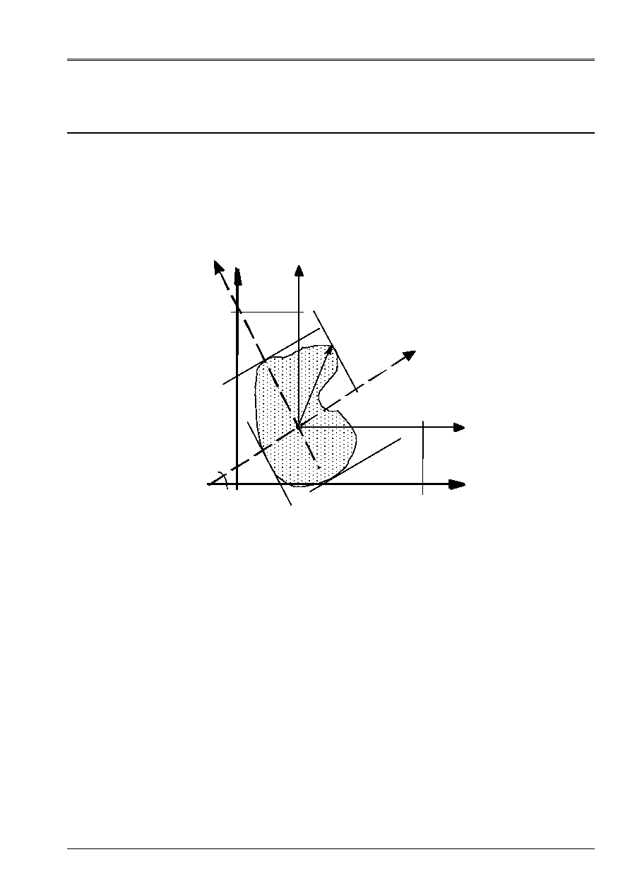
Reference marks used for the geometrical characteristics
Two reference marks are used:
· the reference mark
OXY
of description of the mesh 2D;
· the main reference mark of inertia
Gyz
. cross-section, whose denomination corresponds to that
used with the description of the elements of neutral fiber beam
Gx
[U4.42.01].
G
X
Y
y (pri
ncipal
)
Z_MI
NR
Y_MAX
R_
MA
X
Z_MA
X
Y_MIN
ALPHA
X
CD
G
_
Y
CDG_X
Y
O
(the main thing)
Z
Definition of the geometrical magnitudes relating to a section of beam
4.2
Sizes available in the produced table
4.2.1 Characteristics
geometrical
These characteristics are given in the table for all the mesh and each group of
list
lgm
(which can correspond to a half or a quarter of the section if the key words
SYME_X
or
SYME_Y
are present).
4.2.1.1 Characteristics of the mesh read
·
surface:
AIRE_M
·
position of the center of gravity:
CDG_X_M,
CDG_Y_M
·
moments and product of inertia of surface, in the center of gravity G in reference mark GXY:
IX_G_M
IY_G_M
IXY_G_M

Code_Aster
®
Version
7.4
Titrate:
Macro-control
MACR_CARA_POUTRE
Date:
11/02/05
Author (S):
J-L.FLÉJOU
Key
:
U4.42.02-E
Page
:
6/8
Instruction manual
U4.4- booklet: Modeling
HT-66/05/004/A
4.2.1.2 Characteristics of the section of beam
·
surface:
SURFACE
·
position of the center of gravity:
CDG_X,
CDG_Y
·
moments and product of inertia of surface, in the center of gravity
G
in the reference mark
GXY
:
IX_G IY_G IXY_G
· main moments of inertia of surface in the reference mark
Gyz
, usable for the calculation of the rigidity of
bending of the beam:
IY_PRIN_G
and
IZ_PRIN_G
· angle of flow of the reference mark
GXY
with the main reference mark of inertia
Gyz
:
ALPHA
· characteristic distances, compared to the center of gravity
G
section for calculations of
maximum stresses:
Y_MAX
,
Y_MIN
,
Z_MAX
,
Z_MIN
and
R_MAX
.
·
X_P, Y_P
: not calculation of the geometrical moments of inertia
·
IX_P, IY_P, IXY_P
: geometrical moments of inertia in the reference mark
PXY
·
IY_PRIN_P, IZ_PRIN_P
: moments of inertia in the reference mark
Pyz
.
· IXR2, IYR2, IYR2_PRIN_G, IZR2_PRIN_G, IXR2_P, IYR2_P: useful characteristics for
the geometrical matrix of rigidity of elements POU_D_TG and POU_D_T_GM.
4.2.2 Characteristics
“mechanical”
These characteristics are provided in the table for all the mesh and each group of mesh
list
lgm
.
4.2.2.1 Characteristics of torsion
· constant of torsion:
CT
The resolution of a stationary thermal problem of unknown factor phi makes it possible to determine
constant of torsion and stresses shear.
· radius of torsion:
RT
The radius of torsion “RT” can vary along external contour; indeed, for a section
unspecified, shearings due to torsion vary on the edge. One chooses to take the value of
Rt leading to shearings maximum on the external edge, i.e. the maximum value of Rt
(in absolute value) on external contour. Moreover, if the section is alveolate, there are several
“several radii of torsion”: Rt = 2 * A (K)/L (K) (or A (K) represents the surface of the cell K and L (K) sound
perimeter).
If one is satisfied to seek the maximum value of shearing, it is necessary to take the maximum of
Rt values obtained on the external edge and the cells.
· Position of the center of torsion (point C) in the reference mark
GXY
:
PCTX
and
PCTY
. One deduces some
the eccentricity of the center of torsion (component of CG in the main reference mark of inertia
Gyz
):
EY
and
EZ.
· Constant of roll (usable for modelings
POU_D_TG
and
POU_D_TGM
with
7 degrees of freedom):
JG
4.2.2.2 Characteristics of shearing
The coefficients of shearing are given, in the main reference mark of inertia
Gyz
, in the form of
report/ratio (> 1) of the total surface to the actually sheared surface:
AY
and
AZ
4.3
Assignment of the sizes in AFFE_CARA_ELEM
The values contained in this table can be in control AFFE_CARA_ELEM for one
calculation of the beam type.
In AFFE_CARA_ELEM, the characteristics are to be provided in the main reference mark of inertia (G, y, Z).
Quantities required (IY, IZ.) correspond to those calculated in the main reference mark of inertia
defined starting from G, X, Y (
IY_PRIN_G
,
IZ_PRIN…).
It is thus necessary to take guard with directing well the local reference mark of the elements of beam (key word
ORIENTATION of AFFE_CARA_ELEM) in order to affect the quantities correctly.
It is possible to directly provide (via variables python) the characteristics of the sections
(general) resulting from a calculation with MACR_CARA_POUTRE. This is implemented in the test
SSLL107F.
Code_Aster
®
Version
7.4
Titrate:
Macro-control
MACR_CARA_POUTRE
Date:
11/02/05
Author (S):
J-L.FLÉJOU
Key
:
U4.42.02-E
Page
:
7/8
Instruction manual
U4.4- booklet: Modeling
HT-66/05/004/A
5 Examples
of use
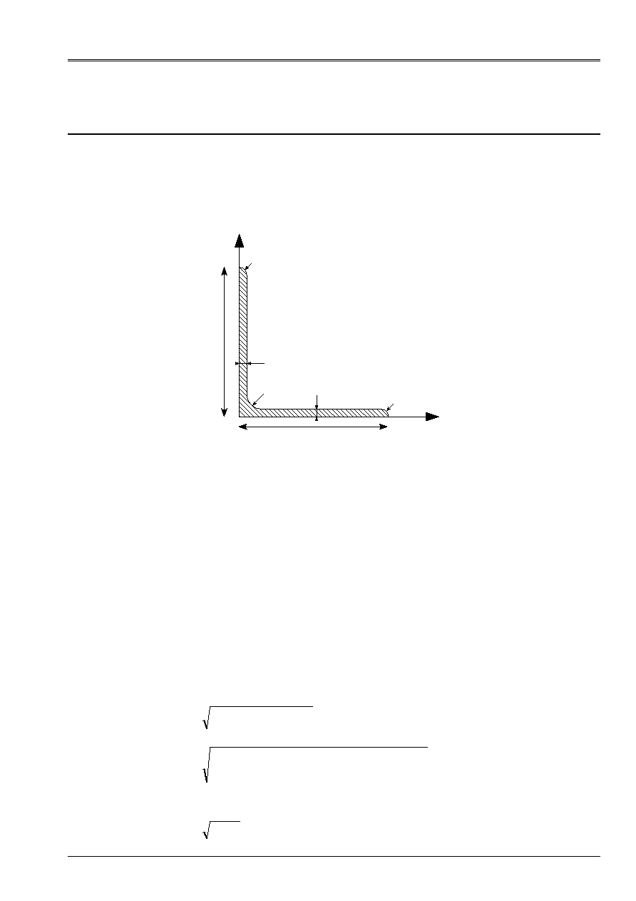
5.1
Characteristic of a section in angle with equal wings
(50 X 50 X 8) treated by test SSLL107A [V1.01.105].
5.1.1 Section
studied
With
With
R1
R1
R
To = 0.0500
E
= 0.0080
R = 0.0050
R1 = 0.0025
E
E
Y
X
5.1.2 Command file
TCARA = MACR_CARA_POUTRE (GROUP_MA_BORD = “LSURF”, NODE = “N1”, INFORMATION = 2)
or LSURF is the group of the linear meshs of the contour of the section.
5.1.3 Characteristics
geometrical obtained
The characteristics of the mesh are identical to those of the section. They are in conformity with those
found in the “Catalog of iron and steel products OTUA: Condition of uses in construction
metal - 1959 "
AIRE_M
=
SURFACE
=
7.39E-4
CDG_X_M
=
CDG_X
=
1.53148E-02
CDG_Y_M
=
CDG_Y
=
1.53148E-02
IX_G_M
=
IX_G
=
1.64141E-07
IY_G_M
=
IY_G
=
1.64141E-07
IXY_G_M
=
IXY_G
=
- 9.48843E-08
IY_PRIN_G
=
2.59025E-07
IZ_PRIN_G
=
6.92568E-08
(
)
(
) (
)
(
)
(
)
(
)
(
)
(
)
ALPHA
45
OG
CDG_ X
CDG_ Y
2.166E
02
Y_ MIN
OG
2.166E
02
Y_ MAX
WITH - R
E - R
R
OG
1.465E
02
Z_ MIN
With
3.536E
02
Z_ MAX
With
3.536E
02
R_ MAX
A/2
With
OG
3.792E
02
1
2
1
2
1
2
2
=
=
+
=
=
=
=
+
+
-
=
= -
=
=
=
=
+
=
°
-
-
-
-
-
-
-
-
-
-
2
2
4
4
4
4
cos
/
cos
/
cos
/
cos
/
Code_Aster
®
Version
7.4
Titrate:
Macro-control
MACR_CARA_POUTRE
Date:
11/02/05
Author (S):
J-L.FLÉJOU
Key
:
U4.42.02-E
Page
:
8/8
Instruction manual
U4.4- booklet: Modeling
HT-66/05/004/A
5.1.4 Characteristics
mechanics
CT =
1.596E8
RT =
1.164E2
PCT_X = 4.665E3
PCT_Y = 4.665E3
EY =
1.51E2
EZ =
0
AY =
2.174
AZ =
2.174
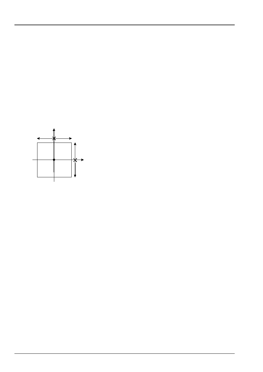
5.2
Full rectangle (treaty by test ZZZZ105G)
5.2.1 Section
studied
5.2.2 Order
TCARS = MACR_CARA_POUTRE (GROUP_MA_BORD = “LR1”, NODE = “N64”)
5.2.3 Characteristics
geometrical obtained
PLACE
AIRE_M
CDG_X_M
CDG_Y_M
IX_G_M
IY_G_M
IXY_G_M
0.000003
1.00E-03
4.24E-18 - 3.39E-18 2.08E-07
3.33E-08
2.65E-23
GR1
5.00E-04
2.20E-17 - 1.25E-02 2.60E-08
1.67E-08
3.97E-23
GR2
5.00E-04
- 8.47E-18
1.25E-02
2.60E-08
1.67E-08
5.62E-23
PLACE
SURFACE
CDG_X
CDG_Y IX_G IY_G IXY_G IY_PRIN_G IZ_PRIN_G ALPHA
0.000003
1.00E-03 4.24E-18 - 3.39E-18 2.08E-07 3.33E-08 2.65E-23 3.33E-08 2.08E-07 9.00E+01
GR1
5.00E-04 2.20E-17 - 1.25E-02 2.60E-08 1.67E-08 3.97E-23 1.67E-08 2.60E-08 9.00E+01
GR2
5.00E-04 - 8.47E-18 1.25E-02 2.60E-08 1.67E-08 5.62E-23 1.67E-08 2.60E-08 9.00E+01
PLACE
X_P
Y_P
IX_P
IY_P
IXY_P
IY_PRIN_P
IZ_PRIN_P
0.000003
0.00E+00
0.00E+00
2.08E-07 3.33E-08 2.65E-23
3.33E-08
2.08E-07
GR1
0.00E+00
0.00E+00
1.04E-07 1.67E-08 - 9.79E-23
1.67E-08
1.04E-07
GR2
0.00E+00
0.00E+00
1.04E-07 1.67E-08 3.31E-24
1.67E-08
1.04E-07
PLACE
Y_MAX
Z_MAX
Y_MIN
Z_MIN
R_MAX
0.000003
2.50E-02
1.00E-02 - 2.50E-02 - 1.00E-02 2.69E-02
GR1
2.50E-02
2.25E-02 - 2.50E-02
2.50E-03 3.36E-02
GR2
2.50E-02
- 2.50E-03 - 2.50E-02 - 2.25E-02 3.36E-02
PLACE
CT
AY
AZ
EY
EZ
PCTX
PCTY
JG
0.000003
-
-
-
-
-
-
-
-
GR1
3.43E-08
1.20E+00
1.20E+00
9.00E-17
- 3.97E-18
2.60E-17 - 1.25E-02 -
GR2
3.43E-08
1.20E+00
1.20E+00
- 4.03E-17
1.19E-16
- 1.27E-16 1.25E-02 -
PLACE
RT
0.000003 1.93871E-2
GR1
1.56391E-2
GR2
1.56391E-2
B
B
y
GR2
GR1
H
H
X
0
B = 0.01
H = 0.025
3 groups of meshs are defined:
GR1 corresponds to the part y 0
GR2
corresponds to the part y 0
LR1 corresponds to the linear meshs of contour