
Code_Aster
®
Version
7.4
Titrate:
Operator
DEFI_OBSTACLE
Date:
02/02/05
Author (S):
S. LAMARCHE,
Fe WAECKEL, G. JACQUART
Key
:
U4.44.21-G
Page
:
1/6
Instruction manual
U4.4- booklet: Modeling
HT-66/05/004/A
Organization (S):
EDF-R & D/AMA, SINETICS, EDF-Pole Industry/CNPE of Tricastin
Instruction manual
U4.4- booklet: Modeling
U4.44.21 document
Operator
DEFI_OBSTACLE
1 Goal
To define the geometry of the places of shocks of a telegraphic structure. These places are defined in a plan
perpendicular with the structure modelized by beams POU_D_T and POU_D_E. It is then used by
DYNA_TRAN_MODAL [U4.53.21] for the study of the response of a structure whose displacements are
limited by the presence of this obstacle. One can also define the initial section of a structure
which one will study progressive wear. In this last case, the concept will be used by MODI_OBSTACLE
[U4.44.22].
Product a concept of the type
obstacle
.

Code_Aster
®
Version
7.4
Titrate:
Operator
DEFI_OBSTACLE
Date:
02/02/05
Author (S):
S. LAMARCHE,
Fe WAECKEL, G. JACQUART
Key
:
U4.44.21-G
Page
:
2/6
Instruction manual
U4.4- booklet: Modeling
HT-66/05/004/A
2 Syntax
obstacle = DEFI_OBSTACLE
(
/
TYPE
=
/
“CIRCLE”,
[DEFECT]
/
“PLAN_Y”,
/
“PLAN_Z”,
/
“BI_CERCLE”,
/
“BI_CERC_INT”,
/
“BI_PLAN_Y”,
/
“BI_PLAN_Z”,
/
“DISCRETE”,
/
“CRAYON_900”,
/
“CRAYON_1300”,
/
“GUID_A_CARTE_900”,
/
“GUID_A_GCONT_900”,
/
“GUID_A_GCOMB_900”,
/
“GUID_B_CARTE_900”,
/
“GUID_B_GCONT_900”,
/
“GUID_B_GCOMB_900”,
/
“GUID_C_CARTE_900”,
/
“GUID_C_GCONT_900”,
/
“GUID_C_GCOMB_900”,
/
“GUID_D_CARTE_900”,
/
“GUID_D_GCONT_900”,
/
“GUID_D_GCOMB_900”,
/
“GUID_E_CARTE_900”,
/
“GUID_E_GCONT_900”,
/
“GUID_E_GCOMB_900”,
/
“GUID_F_CARTE_900”,
/
“GUID_F_GCONT_900”,
/
“GUID_F_GCOMB_900”,
/
“GUID_A_CARSP_900”,
/
“GUID_B_CARSP_900”,
/
“GUID_C_CARSP_900”,
/
“GUID_D_CARSP_900”,
/
“GUID_E_CARSP_900”,
/
“GUID_F_CARSP_900”,
/
“GUID_A_CARTE_1300”,
/
“GUID_A_GCONT_1300”,
/
“GUID_A_GCOMB_1300”,
/
“GUID_B_CARTE_1300”,
/
“GUID_B_GCONT_1300”,
/
“GUID_B_GCOMB_1300”,
/
“GUID_C_CARTE_1300”,
/
“GUID_C_GCONT_1300”,
/
“GUID_C_GCOMB_1300”,
/
“GUID_D_CARTE_1300”,
/
“GUID_D_GCONT_1300”,
/
“GUID_D_GCOMB_1300”,
/
“GUID_E_CARTE_1300”,
/
“GUID_E_GCONT_1300”,
/
“GUID_E_GCOMB_1300”,
/
“GUID_F_CARTE_1300”,
/
“GUID_F_GCONT_1300”,
/
“GUID_F_GCOMB_1300”,
/
“GUID_A_CARSP_1300”,
/
“GUID_B_CARSP_1300”,
/
“GUID_C_CARSP_1300”,
/
“GUID_D_CARSP_1300”,
/
“GUID_E_CARSP_1300”,
/
“GUID_F_CARSP_1300”,
VALE =
thetar, [l_R]
VERIF
= “FIRM”,
);
Code_Aster
®
Version
7.4
Titrate:
Operator
DEFI_OBSTACLE
Date:
02/02/05
Author (S):
S. LAMARCHE,
Fe WAECKEL, G. JACQUART
Key
:
U4.44.21-G
Page
:
3/6
Instruction manual
U4.4- booklet: Modeling
HT-66/05/004/A
3 Operands
3.1 Operand
TYPE
/
TYPE = typ
The operand
TYPE
allows to give:
·
the form wraps play in the connection of shock by a text among the following:
PLAN_Y
,
PLAN_Z
,
RING
,
DISCRETE
,
BI_PLAN_Y
,
BI_PLAN_Z
,
BI_CERCLE
and
BI_CERC_INT
;
·
the initial section of structures such as the pencils
CRAYON_ *
and them guides
GUID_ * _ * _ *
control rods of the ITEMS 900 and 1300 MW.
Obstacles of the type
PLAN_Y
,
PLAN_Z
,
RING
and
DISCRETE
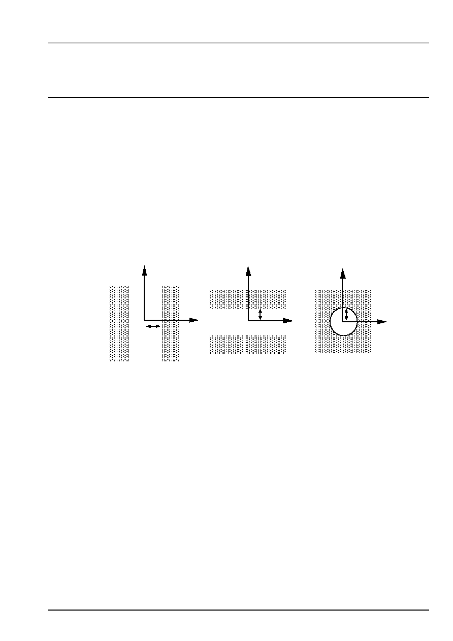
define the geometry of
places of shock enters a mobile structure and an indeformable obstacle. They are traced
below [Figure 3.1-a] according to the selected type.
Zloc
Yloc
play
play
play
Zloc
Zloc
Yloc
Yloc
PLAN_Y
PLAN_Z
RING
Appear 3.1-a
The value of the play and the local reference mark (Xloc, Yloc, Zloc) will be defined in the moment of the use
obstacle (see operator
DYNA_TRAN_MODAL
[U4.53.21]). The origin of this reference mark being it
place of the telegraphic structure considered.
In the case of the obstacle
TYPE
= `
DISCRET'
, the curve should be specified defining it
contour and play simultaneously, using the key word
VALE
.
Code_Aster
®
Version
7.4
Titrate:
Operator
DEFI_OBSTACLE
Date:
02/02/05
Author (S):
S. LAMARCHE,
Fe WAECKEL, G. JACQUART
Key
:
U4.44.21-G
Page
:
4/6
Instruction manual
U4.4- booklet: Modeling
HT-66/05/004/A
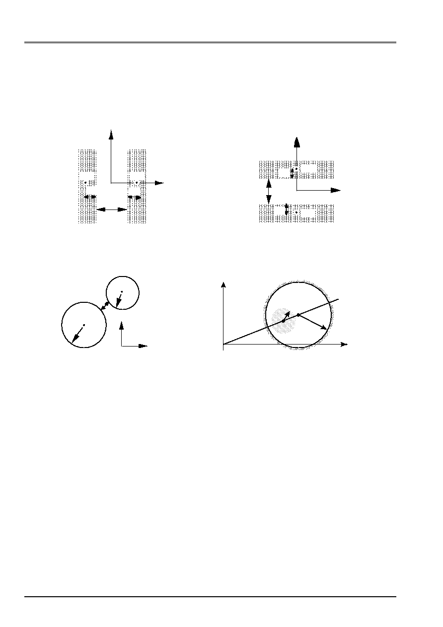
Types
BI_PLAN_Y
,
BI_PLAN_Z,
BI_CERCLE
and
BI_CERC_INT
allow to define them
possible places of contact of the telegraphic structure between two nodes NO1 and pertaining NO2
each one with a mobile structure. Geometries of the connections of plane contact on plan (or
ring on circle) are described on the figure [Figure 3.1-b] below.
Zloc
play
Yloc
BI_PLAN_Y
N02
D2
D1
N01
Zloc
Yloc
BI_PLAN_Z
N01
D1
play
N02
D2
Yloc
Zloc
BI_CERCLE
R1
N01
play
N02
R2
NO1
NO2
R1
R2
Zloc
Yloc
BI_CERC_INT
Appear 3.1-b
The value thicknesses of matter surrounding the nodes of shock (D1 and D2 for one
obstacle of the type
BI_PLAN_ *
, R1 and R2 for an obstacle of the type
BI_CERCLE
or
BI_CERC_INT
) as well as the local reference mark (Xloc, Yloc, Zloc) are defined in the moment of
the use of the obstacle, i.e. in the operator
DYNA_TRAN_MODAL
[U4.53.21].
Several initial forms, in particular for the study of the vibrations of the bunches of
order, are defined. They correspond with the pencil of the various bunches of
order and from their guidance.
Code_Aster
®
Version
7.4
Titrate:
Operator
DEFI_OBSTACLE
Date:
02/02/05
Author (S):
S. LAMARCHE,
Fe WAECKEL, G. JACQUART
Key
:
U4.44.21-G
Page
:
5/6
Instruction manual
U4.4- booklet: Modeling
HT-66/05/004/A
The STANDARD operand then makes it possible to define the geometry of a pencil of control rod
nine of type ITEM 900MW: `CRAYON_900' or of type REP1300MW: “CRAYON_1300”;
and that of the various parts of a guidance of bunch nine: type starting with GUID
(GUID_ * _ * _ *). The three indications which follow GUID respectively make it possible to define:
·
the type of pencil of bunch - of A with F - which is inside (the channel of guidance is
different for each type of pencil);
·
the part of the guidance to which the obstacle belongs: CARD if discontinuous guidance;
GCONT if continuous guidance; GCOMB if guidance combustible; CARSP if card with play
increased;
·
and the type of jet engine: 900 if ITEM 900MW or 1300 if ITEM 1300MW.
3.2 Operands
VALE/VERIF
VALE = thetar
In the case of the DISCRETE obstacle it is necessary to specify the curve defining contour and the play
at the same time, using key word VALE.
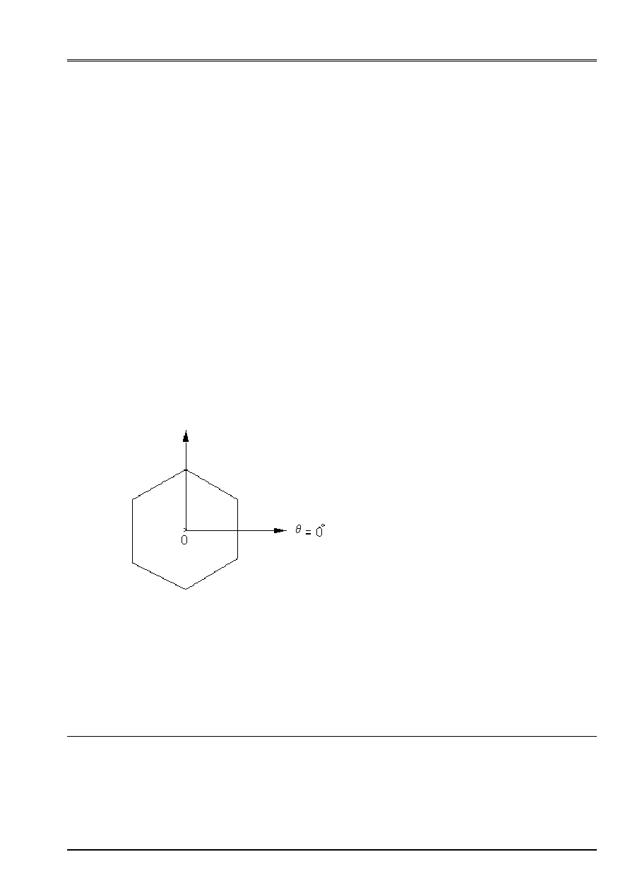
thetar is the list of realities making it possible to describe the contour of the obstacle of the DISCRETE type in
polar co-ordinates. One describes the obstacle like a curve planes into polar while giving
couples of values, the first being the angle in degrees of 0 with 360°, the second the radius
[Figure 3.2-a].
Appear 3.2-a
VERIF = “FIRM”
Key word allowing to check if the curve given into polar is well closed.
4 Phase
of execution
It is checked that the number of values behind VALE is even and that the curve defined in co-ordinates
polar is well closed (operand VERIF = “FIRM”).
VALE
= (0.0, 0.00086,
30.0,
0.00086,
90.0,
0.001,
150.0,
0.001,
210.0,
0.001,
270.0,
0.001,
330.0,
0.001,
360.0,
0.00086,)

Code_Aster
®
Version
7.4
Titrate:
Operator
DEFI_OBSTACLE
Date:
02/02/05
Author (S):
S. LAMARCHE,
Fe WAECKEL, G. JACQUART
Key
:
U4.44.21-G
Page
:
6/6
Instruction manual
U4.4- booklet: Modeling
HT-66/05/004/A
Intentionally white left page.