
Code_Aster
®
Version
8.2
Titrate:
Operator
POST_K1_K2_K3
Date:
31/01/06
Author (S):
E. CRYSTAL, C. REZETTE
Key
:
U4.82.05-D1
Page:
1/8
Instruction manual
U4.8- booklet: Postprocessing and dedicated analyzes
HT-62/06/004/A
Organization (S):
EDF-R & D/AMA, DeltaCAD
Instruction manual
U4.8- booklet: Postprocessing and dedicated analyzes
Document: U4.82.05
Operator
POST_K1_K2_K3
1 Goal
To calculate the factors of intensity of the stresses in 2D and 3D for plane fissures.
This operator allows to calculate K1, K2 in 2D (plane and axisymmetric) and K3 in 3D by extrapolation
jumps of displacements on the lips of the fissure. This method is applicable only to the case of
plane fissures, in homogeneous and isotropic materials.
The method used is less precise than calculation starting from the bilinear form of the rate of refund
energy and singular displacements, usable in 2D with option CALC_K_G of the operator
CALC_G_THETA_T [U4.82.03]. It however makes it possible to easily obtain approximate values
factors of intensity of the stresses, in particular in the case 3D, for which method of
singular displacements is operational only with linear elements (option CALC_K_G of
operator CALC_G_LOCAL_T [U4.82.04]).
Product a concept of the type counts.

Code_Aster
®
Version
8.2
Titrate:
Operator
POST_K1_K2_K3
Date:
31/01/06
Author (S):
E. CRYSTAL, C. REZETTE
Key
:
U4.82.05-D1
Page:
2/8
Instruction manual
U4.8- booklet: Postprocessing and dedicated analyzes
HT-62/06/004/A
2 Syntax
tk [table] = POST_K1_K2_K3
(
MODELING =
/“3D”,
/
“AXIS”,
/
“D_PLAN”,
/
“C_PLAN”,
MATER
= chechmate
,
[material]
/
RESULT
= resu,
/
[evol_elas]
/
[evol_noli]
/
TABL_DEPL_SUP
=
tdsup,
[table]
TABL_DEPL_INF
=
tdinf,
[table]
/TOUT_ORDRE = “YES”,
/
NUME_ORDRE =
lnuor,
[L_I]
/
LIST_ORDRE =
lnuor,
[listis]
/
INST =
l_inst, [l_R]
PRECISION
=
1.E-6,
[DEFECT]
prec,
CRITERION =
/
“RELATIVE”, [DEFECT]
/
“ABSOLUTE”
,
/
LIST_INST
=
l_inst, [listR8]
PRECISION
=
1.E-6,
[DEFECT]
prec,
CRITERION =
/
“RELATIVE”, [DEFECT]
/
“ABSOLUTE”
,
ABSC_CURV_MAXI=
dmax,
[R]
VECT_K1 =
(y1, y2, y3),
[R]
/
FOND_FISS
=
melts,
[fond_fiss]
/
ALL
=
“YES”,
/ |
NODE
=
noeu,
[l_noeud]
|
GROUP_NO
=
gr_noeu,
[l_gr_noeud]
/ |
SANS_NOEUD =
noeu,
[l_noeud]
|
SANS_GROUP_NO
=
gr_noeu,
[l_gr_noeud]
MESH = my,
[mesh]
PREC_VIS_A_VIS
=
/
1.E-1,
[DEFECT]
/
epsi,
[R]
SYME_CHAR
=
/
“WITHOUT”,
[DEFECT]
/
“SYME”,
TITRATE = title
,
[l_Kn]
INFORMATION
=
/
1,
[DEFECT]
/2,
)

Code_Aster
®
Version
8.2
Titrate:
Operator
POST_K1_K2_K3
Date:
31/01/06
Author (S):
E. CRYSTAL, C. REZETTE
Key
:
U4.82.05-D1
Page:
3/8
Instruction manual
U4.8- booklet: Postprocessing and dedicated analyzes
HT-62/06/004/A
3 Operands
3.1 Operand
MODELING
MODELING =
/“3D”,
/
“AXIS”,
/
“D_PLAN”,
/
“C_PLAN”,
Allows to define the type of calculation to be carried out: 3D (in which case one K3 will calculate) or 2D.
This modeling must be coherent with the model used for the calculation of
displacements.
3.2 Operand
MATER
MATER =
chechmate,
[material]
Concept of the material type containing the elastic characteristics of fissured material
The material must be homogeneous, isotropic and elastic linear.
If the properties materials depend on the temperature (key word ELAS_FO
DEFI_MATERIAU), the processing is different according to the type of modeling:
·
for a modeling 2D (“AXIS”, “D_PLAN”, “C_PLAN”), characteristics
materials are obtained at the temperature of reference TEMP_DEF_ALPHA of
DEFI_MATERIAU;
·
for a modeling 3D (“3D”), if the key word RESULT is indicated, then them
characteristics materials are calculated starting from the temperature of the nodes
bottom of fissure; if key words TABL_DEPL_SUP/TABL_DEPL_INF are
informed, then the characteristics materials are calculated from
temperature of reference TEMP_DEF_ALPHA of DEFI_MATERIAU.
Note:
In 3D, it is thus recommended to inform the key word RESULT if the properties
materials depend on the temperature.
3.3 Operands
TABL_DEPL_SUP/TABL_DEPL_INF/RESULT
/
RESULT = resu,
/
TABL_DEPL_SUP
=
tdsup,
[table]
TABL_DEPL_INF
=
tdinf,
[table]
Concepts of the type counts resulting from POST_RELEVE_T containing displacements from
nodes of the upper lip (tdsup) and those of the lower lip (tdinf).
In 2D, these lips are segments of straight lines. tdsup and tdinf thus contain them
values of the two components of displacement on each upper lip and
lower. The nodes of the lips must be ordered (bottom of fissure towards the lip
fissure).
In 3D, tdsup and tdinf contain displacements of all the nodes of the plans
representing the upper lips and lower.
The two tables tdsup and tdinf must be present simultaneously safe if one
modelize that half of the solid compared to the fissure (SYME_CHAR = `SYME'), to which
case only the table of displacement of the upper lip is necessary.
To avoid extracting displacements by POST_RELEVE_T, it is possible to provide
directly a concept result (key word RESULT).
Code_Aster
®
Version
8.2
Titrate:
Operator
POST_K1_K2_K3
Date:
31/01/06
Author (S):
E. CRYSTAL, C. REZETTE
Key
:
U4.82.05-D1
Page:
4/8
Instruction manual
U4.8- booklet: Postprocessing and dedicated analyzes
HT-62/06/004/A
3.4 Operands INST, LIST_INST, TOUT_ORDRE, NUME_ORDRE,
LIST_ORDRE
Cf [U4.71.00].
3.5 Operand
ABSC_CURV_MAXI
ABSC_CURV_MAXI=
dmax [R]
Outdistance maximum calculation of the factors of intensity of the stresses starting from the bottom of
fissure. In practice, the precision of the results is worse if one is located very far from
melts of fissure [R7.02.08]. It is thus advised to choose dmax smallest possible
(about 3 to 4 elements, or about the radius of the radiant mesh, it
case falling due).
3.6 Operand
VECT_K1
VECT_K1 = (y1, y2, y3)
[R]
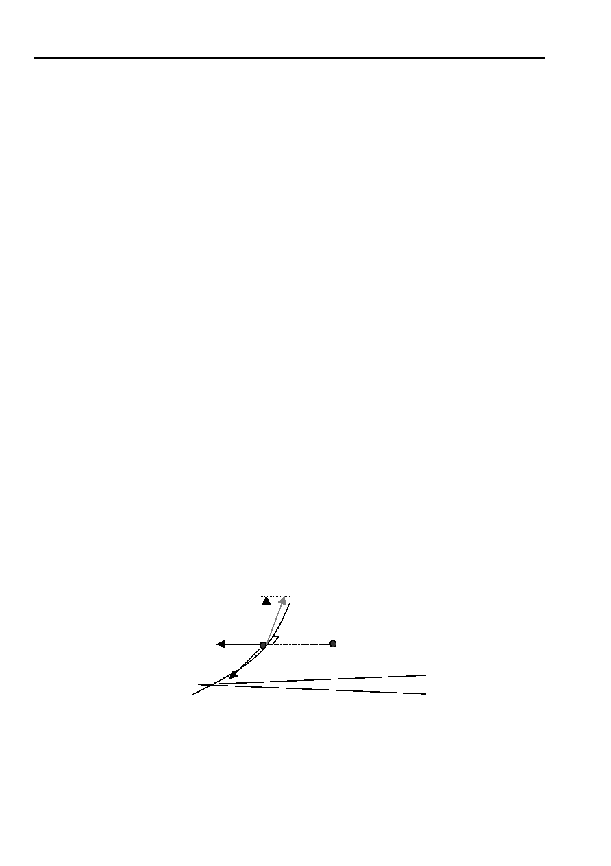
POST_KI_K2_K3 functions for a fissure planes and carries out the calculation of the factors
of intensity of the stresses in the normal plan with each node of the bottom of fissure.
For the calculation of the factors of intensity of the stresses, one defines a local reference mark for
each node of the bottom of fissure in the following way:
center X1: normal vector in the plan of the fissure;
center X2: normal vector at the bottom of fissure;
center X3: tangent vector at the bottom of fissure.
These axes are in the following way given:
·
the axis X2 is determined by the orientation of the vector connecting a node (NR
L
) located on
one of the faces of the fissure towards the node of the bottom of fissure, in the plan
normal with this node (NR
F
);
·
the axis X1 is deduced from the axis provided by the user by key word VECT_K1. X1
must be the normal axis in the plan of the fissure. The who can user not
to very precisely know the normal in the plan of fissure, the axis X1 is calculated in
projecting vector VECT_K1 on the orthogonal level with the axis X2:
X1 = VECT_K1 (VECT_K1.X2) X2;
· the axis X3 is determined by the vector product (axis X1, axis X2).
Vector VECT_K1 thus makes it possible to direct the axis X1, normal in the plan of the fissure, in
coherence with the definition of the lips of fissure LEVRE_INF and LEVRE_SUP.
Displacements in this local reference mark enable us to calculate:
K1: mode I of opening, discontinuity of displacement following the axis X1;
K2: mode II of plane shearing, discontinuity of displacement following the axis X2;
K3: mode III of shearing antiplan, discontinuity of displacement following the axis X3.
VECT_K1
X1
X2
X3
NR
F
NR
L
LEVRE_SUP
LEVRE_INF

Code_Aster
®
Version
8.2
Titrate:
Operator
POST_K1_K2_K3
Date:
31/01/06
Author (S):
E. CRYSTAL, C. REZETTE
Key
:
U4.82.05-D1
Page:
5/8
Instruction manual
U4.8- booklet: Postprocessing and dedicated analyzes
HT-62/06/004/A
3.7 Operands
FOND_FISS/MESH
/PREC_VIS_A_VIS/NODE
/GROUP_NO/SANS_NOEUD/SANS_GROUP_NO
/
FOND_FISS= melts,
[fond_fiss]
MESH =
my, [mesh]
PREC_VIS_A_VIS
=
/
1.D-1,
[DEFECT]
/
epsi,
[R]
/
ALL
= “YES”,
/
|
NODE =
noeu,
[l_noeud]
|
GROUP_NO
=
gr_noeu,
[l_gr_noeud]
/
|
SANS_NOEUD
=
noeu,
[l_noeud]
|
SANS_GROUP_NO
=
gr_noeu,
[l_gr_noeud]
For a modeling 3D, it is possible to automate for each node of the bottom of
fissure the search of the nodes located on normal segments at the bottom of fissure and
belonging to the upper lips and lower, then to carry out the calculation of the factors
of intensity of the stresses.
It is necessary for that to provide a concept fond_fiss created by the control
DEFI_FOND_FISS, as well as a precision for the geometrical search of the nodes
located on the normals at the various nodes of the bottom of fissure. It is also necessary to provide
the name of the mesh on which one carries out the post processing.
By defect, the calculation of the stress intensity factors is done only on
nodes ends of the meshs composing the bottom of fissure (thus all nodes for
linear elements, and a node on two for the quadratic elements).
The user with the possibility of:
·
to select certain nodes ends of the bottom of fissure (key words NODE and
GROUP_NO);
·
to exclude from the nodes of the bottom of fissure (key words SANS_NOEUD and
SANS_GROUP_NO);
·
to make calculation on all the nodes mediums and ends of the bottom of fissure
(key word ALL).
At the time of automatic search for each node of the bottom of fissure, the operator
select the nodes checking the three following conditions:
·
outdistance D with the straight line perpendicular to the bottom of fissure: D <
epsi
.d, where D is
the minimal distance between two successive nodes of the bottom of fissure;
·
outdistance R compared to the bottom of fissure: R < ABSC_CURV_MAXI (1+
epsi
/10);
·
outdistance L compared to its opposite on the other lip:
L <
epsi
.ABSC_CURV_MAXI.
where
epsi
is the value of the provided precision (key word PREC_VIS_A_VIS). By defect
epsi
is worth 0,1. To increase the value of
epsi
amounts increasing the number of nodes
potentially retained for calculation.
3.8 Operand
SYME_CHAR
SYME_CHAR
=
/
“WITHOUT”, [DEFECT]
/
“SYME”,
This key word makes it possible to indicate if the loading is symmetrical if one
modelize that half of the solid compared to the fissure. Normal displacements of
lips are then supposed to be opposite (K1
0) and equal tangent displacements
(either K2 = K3 = 0).

Code_Aster
®
Version
8.2
Titrate:
Operator
POST_K1_K2_K3
Date:
31/01/06
Author (S):
E. CRYSTAL, C. REZETTE
Key
:
U4.82.05-D1
Page:
6/8
Instruction manual
U4.8- booklet: Postprocessing and dedicated analyzes
HT-62/06/004/A
3.9 Operand
INFORMATION
INFORMATION
=
/
1,
[DEFECT]
/2,
Level of messages in the file message: if INFORMATION is worth 2, one provides the list of
all computed values for all the treated nodes.
3.10 Operand
TITRATE
TITRATE = title,
Titrate that one wants to give to the result of the control.
4
Precautions and consultings of use
4.1 Count
produced
Three different methods are systematically used to carry out the calculation of K in each
node of the bottom of fissure [R7.02.08]:
·
Method 1: for each node of the segment of interpolation, one calculates the jump of the field of
displacements squared and one divides it by R. Différentes values from K1 (resp. K2, K3) are
obtained (with a multiplicative factor near) by extrapolation in R =0 of the segments of straight lines
thus obtained.
·
Method 2: one traces the jump of the field of displacements squared according to R. Them
approximations of K1 are (always except for a multiplicative factor) equal to the slope of
segments connecting the origin to the various points of the curve.
·
Method 3: one identifies the stress intensity factor K1 (resp. K2, K3) starting from the jump
of displacement by a method of least squares. One obtains a single value of K1,
K2 and K3 for each node of the bottom of fissure.
The control
POST_K1_K2_K3
product a concept of the type
count
. This table contains, for each
node of the bottom of fissure and for each of the 3 methods:
·
the maximum value
K1_MAX
and the minimal value
K1_MIN
factors of intensity of
stresses in mode I calculated for each node of the segment of interpolation;
·
K2_MAX
and
K2_MIN
for mode II;
·
K3_MAX
and
K3_MIN
for mode III in 3D;
·
The rate of refund of energy G (maximum value
G_MAX
and minimal
G_MIN
) calculated with
to leave the factors of intensity of the stresses by the formula of Irwin.
The table can be printed by
IMPR_TABLE
[U4.91.03]. Method 3 produces only one value
of K1, K2, K3 and G, the minimal and maximum values corresponding are thus equal in
table result.
If INFORMATION is worth 2, all intermediate calculations are displayed in the file message. It is announced that
the column entitled
SAUT_DX
(resp.
SAUT_DY
and
SAUT_DZ)
in the tables of the file message
corresponds to the jump of displacement following the axis X1 (resp. X2 and X3), multiplied by a coefficient
depending on material (in 3D: E
(2)/8 (1 ²)), the whole squared.

Code_Aster
®
Version
8.2
Titrate:
Operator
POST_K1_K2_K3
Date:
31/01/06
Author (S):
E. CRYSTAL, C. REZETTE
Key
:
U4.82.05-D1
Page:
7/8
Instruction manual
U4.8- booklet: Postprocessing and dedicated analyzes
HT-62/06/004/A
4.2
Precautions and consultings
The assumptions necessary to the validity of this method are:
1) the fissure is plane,
2) the behavior is elastic, linear, isotropic and homogeneous and the structure is isothermal,
3) one places oneself in a normal plan at the bottom of fissure, supposed sufficiently regular.
In practice, the mesh will have to comprise sufficient nodes perpendicular to the bottom of
fissure. In addition, the results are clearly improved if if the mesh is made up
quadratic elements, the nodes mediums are moved (edges which touch the bottom of fissure),
with the quarter of these edges by bringing them closer the bottom of fissure. This is possible thanks to the key word
MODI_MAILLE (option “NOEUD_QUART”) of control MODI_MAILLAGE [U4.23.04].
The method used is less precise than the method of singular displacements [R7.02.05]. One
can however have an idea of the precision of the results by comparing the value of G (provided in
the table result and calculated starting from K1, K2 and K3 by the formula of Irwin) with that obtained with
CALC_G_THETA_T [U4.82.03].
In 2D, the lips are segments of straight lines, and the nodes must be ordered (bottom of
fissure towards the lip of fissure).
Calculation by interpolation of the jumps of displacement requires to have at least 3 nodes on
normal at the bottom of fissure. If the number of nodes is not sufficient, an alarm is emitted and it
calculation continues, if necessary, for the following node of the bottom of fissure. One can in this case:
·
that is to say to increase curvilinear X-coordinate maximum ABSC_CURV_MAXI to go to seek
nodes further away from the bottom of fissure;
·
that is to say to increase parameter PREC_VIS_A_VIS, which returns to being less demanding in
selection of the nodes for calculation.

Code_Aster
®
Version
8.2
Titrate:
Operator
POST_K1_K2_K3
Date:
31/01/06
Author (S):
E. CRYSTAL, C. REZETTE
Key
:
U4.82.05-D1
Page:
8/8
Instruction manual
U4.8- booklet: Postprocessing and dedicated analyzes
HT-62/06/004/A
5 Example
Fissure circular in a block 3D (test SSLV134D).
MA = LIRE_MAILLAGE ()
LEVINF1, LEVINFS are the groups containing the surface meshs located on the lips
higher and lower of the fissure. One creates the groups of associated nodes:
MA = DEFI_GROUP (MESH = MA,
CREA_GROUP_NO =_F (GROUP_MA= (
'
LEVINF1
'
,
'
LEVINFS
'
,))
Displacement of the nodes to the quarter of the edges:
MA = MODI_MAILLAGE (MESH = MA, reuse = MA,
MODI_MAILLE =_F (OPTION = “NOEUD_QUART”,
GROUP_MA_FOND = “LFF1”)
)
calculation with MECA_STATIQUE….
FISS = DEFI_FOND_FISS (MESH = MA,
FOND_FISS = _F (GROUP_MA = “LFF1”,
GROUP_NO_ORIG = “NFF1”,
GROUP_NO_EXTR = “NFF2”,
),
LEVRE_SUP = _F (GROUP_MA = “LEVINFS”),
LEVRE_INF = _F (GROUP_MA = “LEVINF1”),
DTAN_ORIG = (1. , 0. , 0. ),
DTAN_EXTR = (0. , 1. , 0. )
)
DEP_SUP = POST_RELEVE_T (ACTION = _F (ENTITLES = “TAB_SUP”,
GROUP_NO = “LEVINFS”,
RESULT = RESU1,
NOM_CHAM = “DEPL”,
NOM_CMP = (“DX” “DY” “DZ”),
OPERATION= “EXTRACTION”)
)
DEP_INF = POST_RELEVE_T (ACTION = _F (ENTITLES = “TAB_INF”,
GROUP_NO = “LEVINF1”,
RESULT = RESU1,
NOM_CHAM = “DEPL”,
NOM_CMP = (“DX” “DY” “DZ”),
OPERATION= “EXTRACTION”)
)
TABK1K3 = POST_K1_K2_K3 (MODELING = “3D”, INFO=2,
FOND_FISS = FISS,
MESH = MA,
MATER = CHECHMATE,
TABL_DEPL_SUP = DEP_SUP,
TABL_DEPL_INF = DEP_INF,
ABSC_CURV_MAXI = 0.539,
IDENTIFY = “LOCAL”,
VECT_Y = (0. 0. 1.)
)