Code_Aster
®
Version
4.0
Titrate:
SDLL08 Fits latticework on plane beams (metal sections)
Date:
07/01/98
Author (S):
B. QUINNEZ
Key:
V2.02.008-C
Page:
1/6
Manual of Validation
V2.02 booklet: Linear dynamics of the beams
HI-75/96/035 - Ind A
Organization (S):
EDF/IMA/MN
Manual of Validation
V2.02 booklet: Linear dynamics of the beams
V2.02.008 document
SDLL08 - Fit latticework on plane beams
(metal sections)
Summary:
This three-dimensional problem first of all consists in carrying out a modal analysis and then to study
harmonic response of a mechanical structure of a plane netting of beams. This test of Mechanics of
Structures corresponds to a dynamic analysis of a linear model having a linear behavior. It
only one modeling includes/understands.
This problem thus makes it possible to test the element of beam of Euler Bernouilli in transverse bending, the calculation of
frequencies and of the modes of vibration by the method of Lanczos and the use of linear relations enters
displacements of two points in modal analysis and harmonic answer.
The results are in agreement with the analytical results of guide VPCS.
Code_Aster
®
Version
4.0
Titrate:
SDLL08 Fits latticework on plane beams (metal sections)
Date:
07/01/98
Author (S):
B. QUINNEZ
Key:
V2.02.008-C
Page:
2/6
Manual of Validation
V2.02 booklet: Linear dynamics of the beams
HI-75/96/035 - Ind A
1
Problem of reference
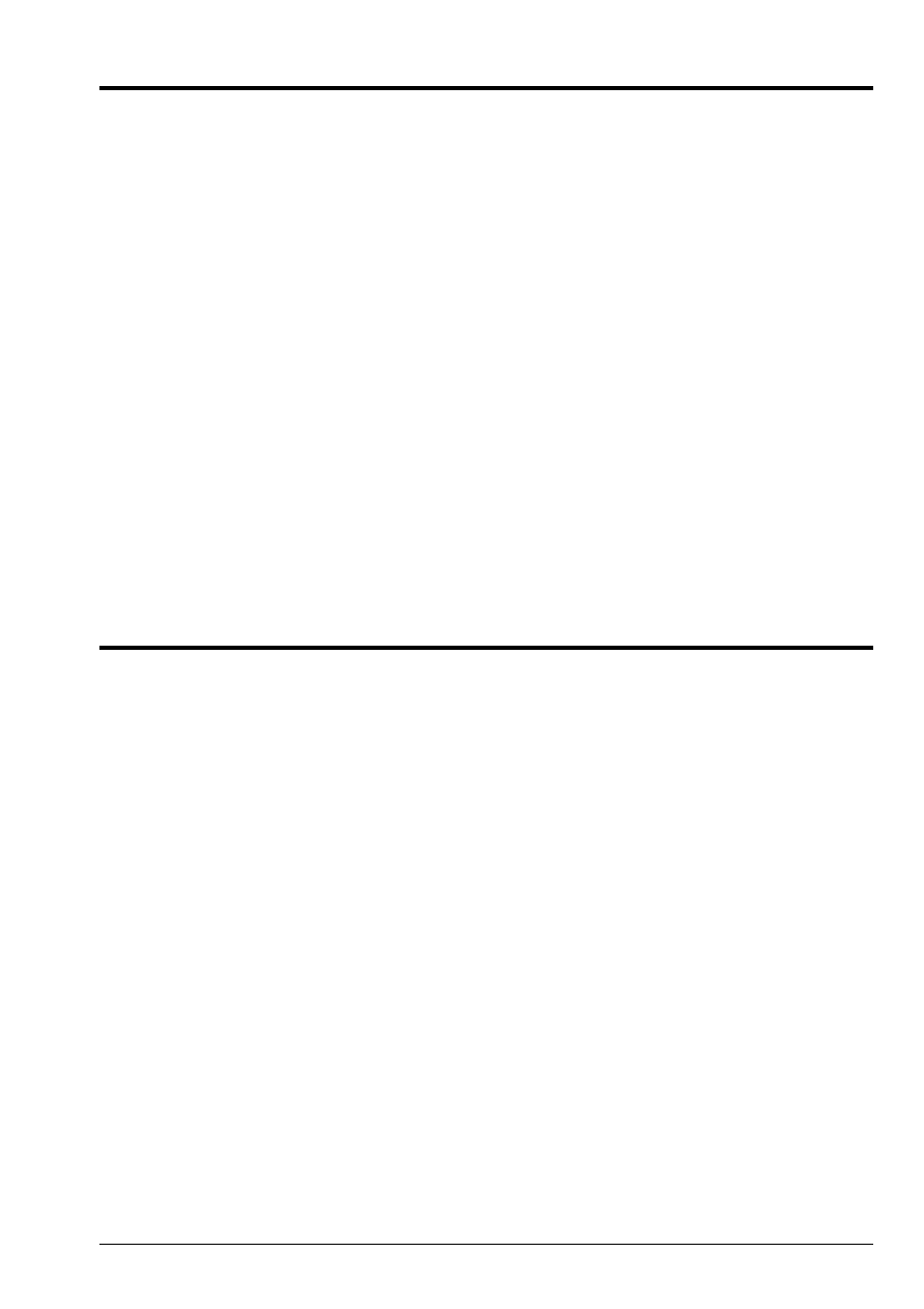
1.1 Geometry
y, v
C
L1
B = H
F
E = I
X, U
D
G
With
L2
F
G
Z, W
Length: L1 = L2 = 5 m
Cross-section (section out of I): IPE 200
surface
To = 2.872 10
3
M
2
moment of inertia
Iz = 1.943 10
5
m
4
(other parameters of beam not used)
Co-ordinates of the points (in meters):
With
B = H
C
D
E = I
F
G
X
2.5
2.5
2.5
2.5
2.5
2.5
0
y
2.5
0.
2.5
2.5
0.
2.5
0.
Z
0.
0.
0.
0.
0.
0.
0.
1.2
Material properties
E
= 2.10
11
AP
= 7.800. kg/m
3
1.3
Boundary conditions and loadings
Points A, C, D, F: (U = v = W = 0.)
Points B, E: rotulée connection (continuity of U, v, W)
Sinusoidal force at the point G
F
G
T
()
=
F
0
sin
T
F
0
=
1
10
5
NR
=
80 rad/S
1.4 Conditions
initial
With T = 0, structure at rest.
Code_Aster
®
Version
4.0
Titrate:
SDLL08 Fits latticework on plane beams (metal sections)
Date:
07/01/98
Author (S):
B. QUINNEZ
Key:
V2.02.008-C
Page:
3/6
Manual of Validation
V2.02 booklet: Linear dynamics of the beams
HI-75/96/035 - Ind A
2
Reference solution
2.1
Method of calculation used for the reference solution
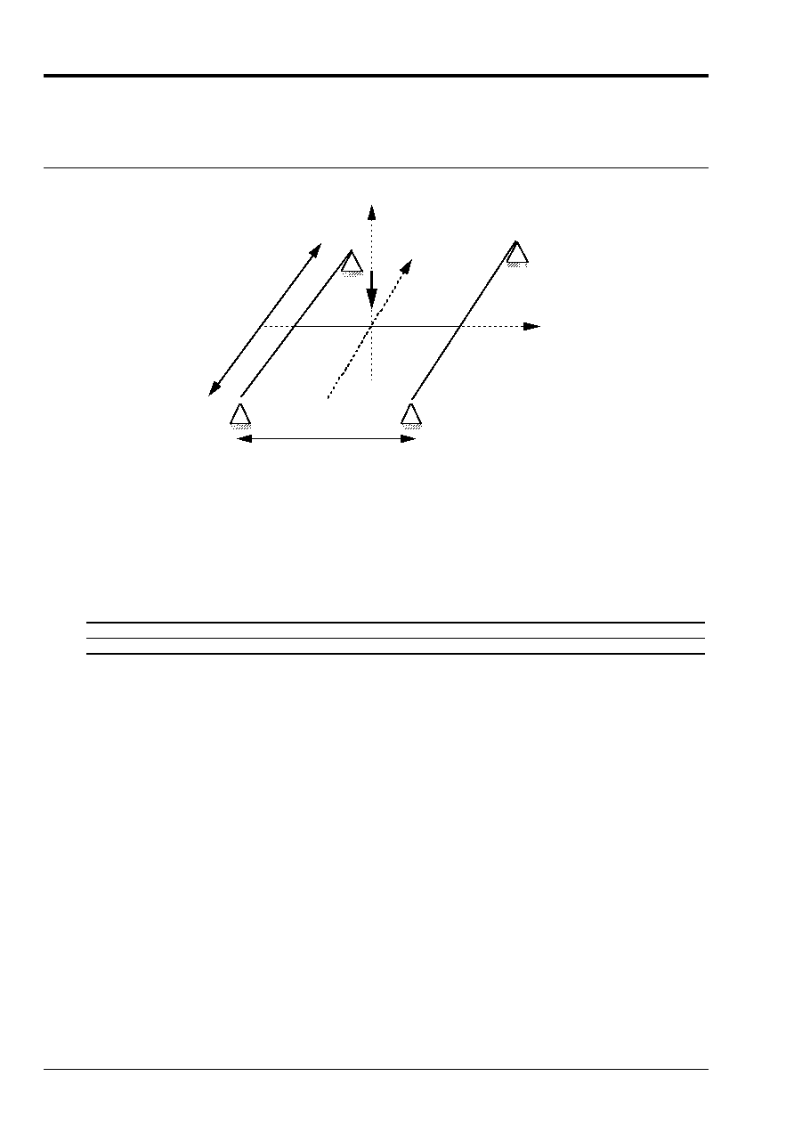
The reference solution is that given in card SDLL08/89 of the guide VPCS which presents
method of calculation in the following way:
A method of Rayleigh-Ritz makes it possible to make calculation with two degrees of freedom from
assumptions of following symmetrical deformations:
·
for the point of X-coordinate there of the spars AC and DF L1 length
W
AB
=
W
B
sin
y
+
L1
2
L1
·
for the point of X-coordinate X of the cross-piece BE L2 length
W
BE
=
W
B
+
W
G
sin
X
+
L2
2
L2
With
C
B
W
B
W
AC
y
L1
B
E
G
W
B
W
BE
X
W
G
L2
2.2
Results of reference
The first two Eigen frequencies and symmetrical clean modes (other frequencies
clean of this system are not studied). For the clean modes, one with the value
following:
W
B
/W
G
In harmonic answer one a:
·
W
B
max
and
W
G
max
,
·
W
B
+
W
G
max
at the point G.
2.3
Uncertainty on the solution
Analytical solution.
2.4 References
bibliographical
[1]
J.M. BIGGS. Introduction to Structural Dynamics. New York: Mc Graw Hill, p.184 (1964).
Code_Aster
®
Version
4.0
Titrate:
SDLL08 Fits latticework on plane beams (metal sections)
Date:
07/01/98
Author (S):
B. QUINNEZ
Key:
V2.02.008-C
Page:
4/6
Manual of Validation
V2.02 booklet: Linear dynamics of the beams
HI-75/96/035 - Ind A
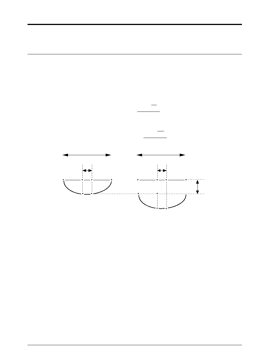
3 Modeling
With
3.1
Characteristics of modeling
One uses the element of beam of Euler Bernouilli
POU_D_E
y
C
F
With
D
B H
G
X
I
E
3 beams:
ABC, DEF, cut out HGI each one in 10 meshs SEG2
The nodes (B, H) and (E, I) have the same co-ordinates.
Limiting conditions:
beams ABC and DEF
DDL_IMPO:
beam HGI
nodes ends
(GROUP_NO: (PABC, PDEF)
DX: 0., DY: 0., DRY: 0. )
(GROUP_NO: (PHGI)
DX: 0., DY: 0., DRX: 0. )
(GROUP_NO: (NACDF)
DZ: 0. )
Liaison_ddl:
Force_nodale:
DZ
B
DZ
H
= 0.
and
DZ
E
DZ
I
= 0.
Node: G
Fz: 1.E5
Names of the nodes:
With = N1
B = N6
C = N11
D = N21
E = N26
F = N31
H = N41
G = N46
I = N51
3.2
Characteristics of the mesh
A number of nodes:
33
A number of meshs and types:
3 * 10 = 30 SEG2
3.3 Functionalities
tested
Controls
Keys
AFFE_CARA_ELEM
BEAM
“GENERAL”
ALL
[U4.24.01]
AFFE_CHAR_MECA
DDL_IMPO
LIAISON_DDL
FORCE_NODALE
GROUP_NO
NODE
[U4.25.01]
AFFE_MATERIAU
ALL
[U4.23.02]
AFFE_MODELE
“MECHANICAL”
'POU_D_E
ALL
[U4.22.01]
DEFI_MATERIAU
ELAS
[U4.23.01]
MODE_ITER_SIMULT
METHOD
CALC_FREQ
“TRI_DIAG”
OPTION
“PLUS_PETITE”
[U4.52.02]
COMB_MATR_ASSE
[U4.53.01]
3.4 Remarks
The blocking of
ddl
DX
and
DY
in all the nodes allows to select only the modes of bending
transverse (in the “vertical” plane).
Code_Aster
®
Version
4.0
Titrate:
SDLL08 Fits latticework on plane beams (metal sections)
Date:
07/01/98
Author (S):
B. QUINNEZ
Key:
V2.02.008-C
Page:
5/6
Manual of Validation
V2.02 booklet: Linear dynamics of the beams
HI-75/96/035 - Ind A
4
Results of modeling A
4.1 Values
tested
Frequency (Hz)
Command of the clean mode
Reference
Aster
% difference
1
2
16.456
38.165
16.4190
38.0468
0.22
0.31
Clean mode: value of W
B
/W
G
Command of the clean mode
symmetrical
Reference
Aster *
% difference
1
2
1.213
0.412
1.213
0.412
0.
0.
*
W
B
= DZ out of B (N6)
W
G
+ W
B
= DZ in G (N46)
mode 1:
W
B
= 0.5480
W
G
+ W
B
= 1.
mode 2:
W
B
= 0.6698
W
G
+ W
B
= 0.9559
Harmonic answer:
Not
Type of value
(m)
Reference
Aster
% difference
B, E
G
G
W
B
max
W
G
max *
W
B
+ W
G
max
0.098
0.125
0.227
0.1003
0.1271
0.2274
2.45
1.60
0.18
4.2 Remarks
Calculations carried out by:
MODE_ITER_SIMULT METHOD: “TRI_DIAG”
OPTION: “PLUS_PETITE”
NMAX_FREQ: 3
One obtains an antisymmetric mode for a frequency F = 22.5676 Hz. This Eigen frequency
depends on the constant of provided torsion; the aforementioned is not defined in the bench-mark data.
The values W
B
/W
G
are not checked in the test but are obtained manually starting from W
B
and W
G
+ W
B
.
The value (W
G
) max is not checked in the test. One has only access to W
B
max and (W
B
+ W
G
)
max. W
G
max is obtained manually by difference.
Contents of the file results:
the first 3 Eigen frequencies, displacement of the nodes B, E, G in harmonic answer.
4.3 Parameters
of execution
Version: 3.02.21
Machine: CRAY C90
System:
UNICOS 8.0
Overall dimension memory:
8 megawords
Time CPU To use:
5 seconds

Code_Aster
®
Version
4.0
Titrate:
SDLL08 Fits latticework on plane beams (metal sections)
Date:
07/01/98
Author (S):
B. QUINNEZ
Key:
V2.02.008-C
Page:
6/6
Manual of Validation
V2.02 booklet: Linear dynamics of the beams
HI-75/96/035 - Ind A
5
Summary of the results
The values of the Eigen frequencies and the clean vectors are obtained with a precision < 0.3%.
The variation of 2.5% on the maximum arrows at the points B and E would deserve to check the solution of
reference, to supplement the validation of the harmonic answer.