
Code_Aster
®
Version
8.2
Titrate:
SDLS114 Calcul of the modal stress intensity factors
Date:
07/11/05
Author (S):
E. CRYSTAL, S. DI DOMIZIO
Key
:
V2.03.114-A
Page:
1/10
Manual of Validation
V2.03 booklet: Linear dynamics of the hulls and plates
HT-66/05/005/A
Organization (S):
EDF-R & D/AMA
Manual of Validation
V2.03 booklet: Linear dynamics of the hulls and plates
Document: V2.03.114
SDLS114 Calcul of the factors of intensity of
stress of a plate fissured by recombination
modal
Summary
This test aims at validating the calculation of the factors of intensity of a plate fissured by modal recombination.
modal factors of intensity, i.e associated each clean mode of vibration of the structure, are calculated with
operators CALC_G_THETA_T (option K_G_MODA) in 2D and CALC_G_LOCAL_T (option K_G_MODA) in 3D.
This test contains a modeling 2D and a modeling 3D. The reference solution results from one
direct temporal resolution of the transitory problem.
Two modelings illustrate the possibility of recombining the modal factors of intensity directly in
the command file by instructions python.
Code_Aster
®
Version
8.2
Titrate:
SDLS114 Calcul of the modal stress intensity factors
Date:
07/11/05
Author (S):
E. CRYSTAL, S. DI DOMIZIO
Key
:
V2.03.114-A
Page:
2/10
Manual of Validation
V2.03 booklet: Linear dynamics of the hulls and plates
HT-66/05/005/A
1
Problem of reference
1.1 Geometry
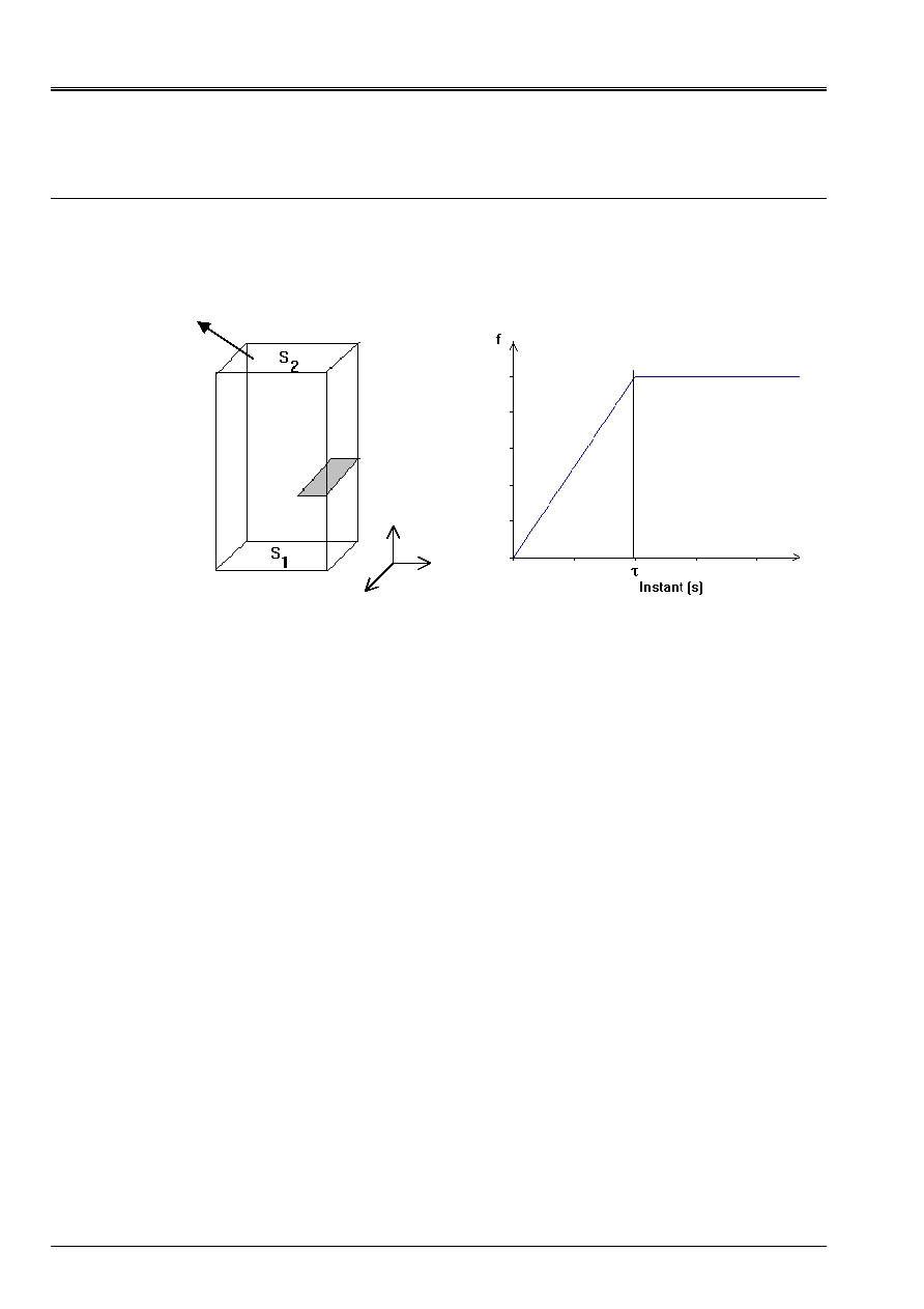
One considers a plate height H = 0,1 m, dispatcher L = 0,05 m and thickness E = 0.005 Mr. Une
fissure is positioned in the middle of the height of the beam, with a depth of 0,1 L.
1.2
Material properties
One considers the conventional properties of a steel:
Young modulus:
E = 2.10
+5
MPa
Poisson's ratio:
= 0.3
Density
= 7800 kg/m
3
1.3
Boundary conditions and loadings
The plate is:
· embedded on surface S
1
;
· subjected to a force F (T) on surface S
2
.
The evolution of the standard of F (T) is traced on the figure above. One takes
= 0,001 S. direction of
the force F (T) is as follows:
· F (T) = F (T) .e
X
for modeling A;
· F (T) = (ae
X
+ Be
y
+ce
Z
) F (T) for modeling B, with B = 2a and C = 0.4 A.
For modeling A, one locks displacements in direction Z (plane problem).
F
X
Z
y
Code_Aster
®
Version
8.2
Titrate:
SDLS114 Calcul of the modal stress intensity factors
Date:
07/11/05
Author (S):
E. CRYSTAL, S. DI DOMIZIO
Key
:
V2.03.114-A
Page:
3/10
Manual of Validation
V2.03 booklet: Linear dynamics of the hulls and plates
HT-66/05/005/A
2
Reference solution
2.1
Method of calculation used for the reference solution
The reference solution is that obtained by a direct temporal resolution of the problem
transient. Operator DYNA_TRAN_EXPLI is used to identify the fields of displacement, with
a diagram of integration in times of Newmark.
The evolution of the stress intensity factors according to time is then calculated by
interpolation of the jumps of displacements (operator POST_K1_K2_K3).
2.2
Result of reference Modélisation A
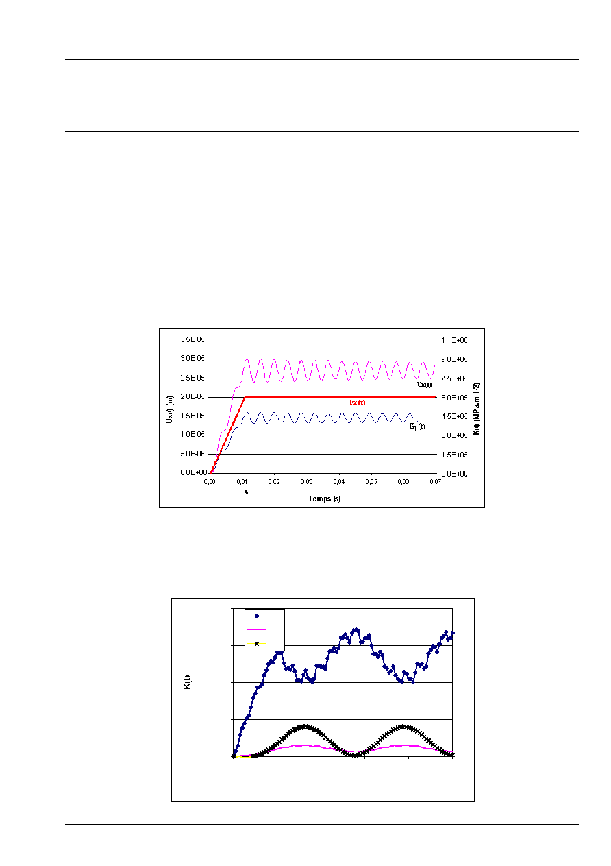
For modeling A, the plate is requested by a force in the plan (O, X, y) and displacements
in direction Z are locked. The result of reference, calculated by direct temporal resolution on
a mesh 2D, is traced on the following figure. The horizontal displacement top of the plate and it
factor of intensity of the stresses oscillate with a frequency corresponding to the first clean mode
structure.
2.3
Result of reference Modélisation B
The evolution of the three factors of intensity of the stresses is traced on the following figure for the node
located in the middle of the bottom of fissure. The oscillations of the factors of intensity of the stresses show
dominating contribution of the first mode of bending of the plate in direction X and the first
mode of bending in direction Z.
0,0E+00
2,0E+05
4,0E+05
6,0E+05
8,0E+05
1,0E+06
1,2E+06
1,4E+06
1,6E+06
0
0,001
0,002
0,003
0,004
0,005
Time (S)
KI
KII
KIII

Code_Aster
®
Version
8.2
Titrate:
SDLS114 Calcul of the modal stress intensity factors
Date:
07/11/05
Author (S):
E. CRYSTAL, S. DI DOMIZIO
Key
:
V2.03.114-A
Page:
4/10
Manual of Validation
V2.03 booklet: Linear dynamics of the hulls and plates
HT-66/05/005/A
2.4
Uncertainty on the solution
The explicit direct resolution of the transitory problem can be regarded as exact. Uncertainty
on the identification of the factors of intensity of the stresses by interpolation of the jumps of displacements
is about 5%.
2.5 References
bibliographical
[1]
E. CRYSTAL, S. DI DOMIZIO: Method theta in breaking process: development
bilinear form G in 3D and application to the case of dynamics low frequency,
Note EDF HT-65/05/024/A, 2005
Code_Aster
®
Version
8.2
Titrate:
SDLS114 Calcul of the modal stress intensity factors
Date:
07/11/05
Author (S):
E. CRYSTAL, S. DI DOMIZIO
Key
:
V2.03.114-A
Page:
5/10
Manual of Validation
V2.03 booklet: Linear dynamics of the hulls and plates
HT-66/05/005/A
3 Modeling
With
3.1
Characteristics of modeling
It is about a modeling 2D plane deformations. The calculation of the evolution of the factors of intensity
stresses according to time is carried out in several stages:
· calculation of the first 15 clean modes of the structure;
· calculation of the modal factors of intensity of the stresses associated these modes by two
methods;
· resolution of the transitory dynamic problem by projection on modal basis;
· recombination of K modal.
3.2
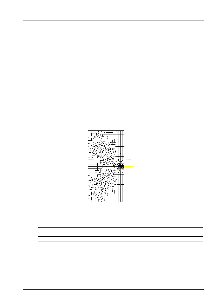
Characteristics of the mesh
The mesh is composed of quadratic elements. It comprises 2000 nodes and 700 meshs and is
refined around the bottom of fissure.
3.3 Functionalities
tested
Controls
MODE_ITER_SIMULT
POST_K1_K2_K3
CALC_G_THETA_T
Option
K_G_MODA
DYNA_TRAN_MODA
Code_Aster
®
Version
8.2
Titrate:
SDLS114 Calcul of the modal stress intensity factors
Date:
07/11/05
Author (S):
E. CRYSTAL, S. DI DOMIZIO
Key
:
V2.03.114-A
Page:
6/10
Manual of Validation
V2.03 booklet: Linear dynamics of the hulls and plates
HT-66/05/005/A
4
Results of modeling A
4.1 Values
tested
Modal values: case test of not-regression
Number of
mode
K
I
(POST_K1_K2_K3)
K
I
(K_G_MODA)
% difference
1 - 1,921.E+10 - 1,898.E+10 1,2
2 - 1,166.E+11 - 1,152.E+11 1,3
3 8,039.E+10
7,948.E+10 1,1
4 - 1,188.E+11 - 1,174.E+11 1,2
5 1,723.E+11
1,705.E+11 1,1
Temporal values K
1
(T): comparison with the explicit resolution
Moment Reference Aster
% difference
0,0005 24055,6
24337,0
1,2
0,001 44676,8
45159,3
1,1
0,002 90592,3
91679,4
1,2
0,003 134065,3
135633,9
1,2
0,004 181113,3
183286,7
1,2
4.2 Notice
The difference between the modal values calculated by interpolation of the jumps of displacement or by
method theta is weak and coherent with that observed on the static problems.
The value of
()
T
K
I
is calculated from
I
K
modal (method K_G_MODA) and of the coefficients of
the resolution about modal base directly in the case test by lines of control in python:
1
()
().
M
I
I
I
I
I
K T
T K
=
=
where coefficients
()
T
I
are the coefficients of modal participation, extracted the result from
operator DYNA_TRAN_MODA, and them
I
I
K
are the modal factors of intensity of the stresses.
The precision obtained is satisfactory taking into account the number of elements retained in the base
modal. The precision increases quickly with the number of modes [bib1].
Code_Aster
®
Version
8.2
Titrate:
SDLS114 Calcul of the modal stress intensity factors
Date:
07/11/05
Author (S):
E. CRYSTAL, S. DI DOMIZIO
Key
:
V2.03.114-A
Page:
7/10
Manual of Validation
V2.03 booklet: Linear dynamics of the hulls and plates
HT-66/05/005/A
5 Modeling
B
5.1
Characteristics of modeling
It is about a modeling 3D. The calculation of the evolution of the factors of intensity of the stresses in
function of time is fulfilled in several stages:
· calculation of the first 50 clean modes of the structure;
· calculation of the modal factors of intensity of the stresses associated these modes by two
methods;
· resolution of the transitory dynamic problem by projection on modal basis;
· recombination of K modal.
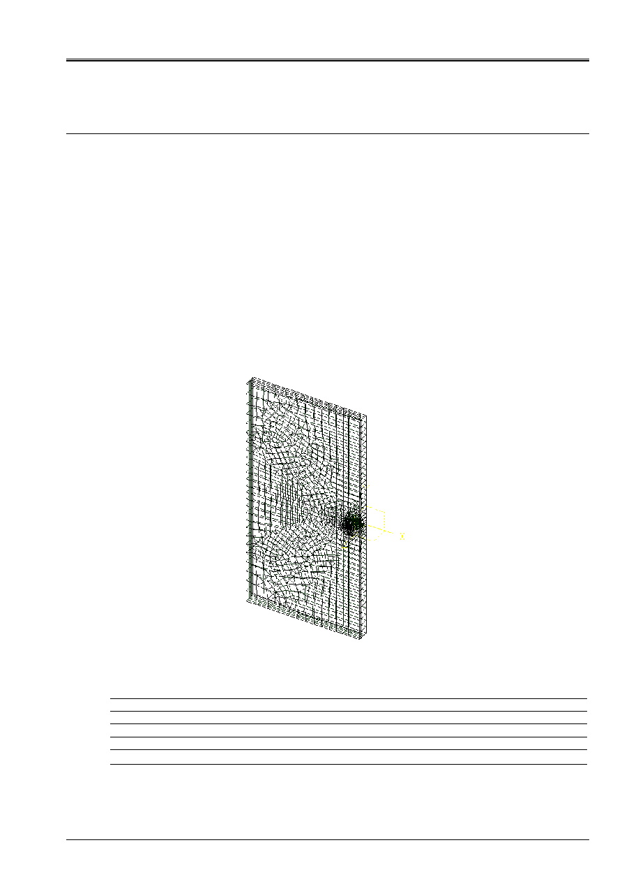
5.2
Characteristics of the mesh
The mesh is composed of linear elements. It comprises 8200 nodes and 8900 meshs and is refined
around the bottom of fissure.
5.3 Functionalities
tested
Controls
MODE_ITER_SIMULT
DEFI_FOND_FISS
POST_K1_K2_K3
DEFI_FISS_XFEM
CALC_G_LOCAL_T
Option
K_G_MODA
DYNA_TRAN_MODA
Code_Aster
®
Version
8.2
Titrate:
SDLS114 Calcul of the modal stress intensity factors
Date:
07/11/05
Author (S):
E. CRYSTAL, S. DI DOMIZIO
Key
:
V2.03.114-A
Page:
8/10
Manual of Validation
V2.03 booklet: Linear dynamics of the hulls and plates
HT-66/05/005/A
6
Results of modeling B
6.1 Values
tested
The values indicated are those found with the node which is in the middle of the bottom of fissure.
Modal values: case test of not-regression
Number of
mode
K
I
(POST_K1_K2_K3)
K
I
(K_G_MODA)
% difference
1 5,631E+09
4,790E+09
14,9
2 8,599E+09
7,291E+09
15,2
3 6,940E+10
5,897E+10
15,0
4 - 2,702E+11
- 2,897E+11
- 7,2
5 - 9,637E+10
- 8,165E+10
15,3
Temporal values K
I
(T): comparison with the explicit resolution
Moment (S)
Reference (AP.
m)
Aster (AP.
m)
% difference
0.0005 696752,4
721825,9
3,6
0.001 1153703,3
1239061,8 7,4
0.002 997675,6
1110569,6
11,3
0.003 1305429,9
1364524,8
4,5
0.004 870347,2
1004735,2
15,4
6.2 Notice
The difference between the modal values calculated by interpolation of the jumps of displacement or by
method theta is high: that is explained by the linear mesh very little refined in the thickness of
the plate.
The value of
()
T
K
I
is calculated from
I
K
modal (method K_G_MODA) and of the coefficients of
the resolution about modal base directly in the case test by lines of control in python:
1
(,)
().
()
M
I
I
I
I
I
K S T
T K S
=
=
where coefficients
()
T
I
are the coefficients of modal participation, extracted the result from
operator DYNA_TRAN_MODA, and them
()
I
I
K S
are the modal factors of intensity of the stresses.
The precision obtained is satisfactory taking into account the number of elements retained in the base
modal (50) and cuts it mesh. The precision increases quickly with the number of modes
[bib1].

Code_Aster
®
Version
8.2
Titrate:
SDLS114 Calcul of the modal stress intensity factors
Date:
07/11/05
Author (S):
E. CRYSTAL, S. DI DOMIZIO
Key
:
V2.03.114-A
Page:
9/10
Manual of Validation
V2.03 booklet: Linear dynamics of the hulls and plates
HT-66/05/005/A
7
Summary of the results
This test makes it possible to validate the calculation of the modal factors of intensity by the operators
CALC_G_LOCAL_T and CALC_G_THETA_T (option K_G_MODA) and illustrate their use for the resolution
of a problem of breaking process in dynamics low frequency by modal recombination.
The relationship between the calculating times of the resolution clarifies and of the resolution about modal base are
ranging between 10 and 50 according to the type of mesh, and the precision of the method of recombination
modal is fully satisfactory.

Code_Aster
®
Version
8.2
Titrate:
SDLS114 Calcul of the modal stress intensity factors
Date:
07/11/05
Author (S):
E. CRYSTAL, S. DI DOMIZIO
Key
:
V2.03.114-A
Page:
10/10
Manual of Validation
V2.03 booklet: Linear dynamics of the hulls and plates
HT-66/05/005/A
Intentionally white left page.