
Code_Aster
®
Version
5.0
Titrate:
SDLV120 Absorption of a wave of compression in an elastic bar
Date:
09/10/01
Author (S):
G. DEVESA, V. TO MOW
Key
:
V2.04.120-A
Page:
1/8
Manual of Validation
V2.04 booklet: Linear dynamics of the voluminal structures
HT-62/01/012/A
Organization (S):
EDF/RNE/AMV
Manual of Validation
V2.04 booklet: Linear dynamics of the voluminal structures
Document: V2.04.120
SDLV120 - Absorption of a wave of compression
in an elastic bar
Summary
One tests the elastic paraxial elements of command 0 intended to apply conditions absorbing to
border of a mesh finite elements to simulate the infinite one in direct transitory calculations.
Are used they to modelize an infinite elastic bar, in 3D or 2D, in which one creates a wave of
pressure by imposing a displacement on the one of the ends. One is interested in nonthe reflection of the wave in
the “infinite” end of the bar.
One tests successively the two direct transitory operators of Code_Aster, namely
DYNA_LINE_TRAN
and
DYNA_NON_LINE
.
Code_Aster
®
Version
5.0
Titrate:
SDLV120 Absorption of a wave of compression in an elastic bar
Date:
09/10/01
Author (S):
G. DEVESA, V. TO MOW
Key
:
V2.04.120-A
Page:
2/8
Manual of Validation
V2.04 booklet: Linear dynamics of the voluminal structures
HT-62/01/012/A
1
Problem of reference
1.1 Geometry
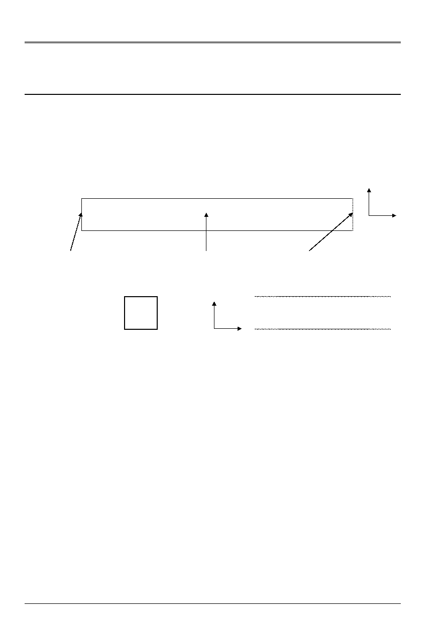
The system considered in the case 3D is that of an elastic bar with square section. One is imposed
displacement according to
X
on one of the vertical faces and one the propagation of a wave observes of
compression. The side surface of the bar is left free. One places the elements absorbents on
face opposed to the face of excitation to simulate the infinite character of the bar in this direction.
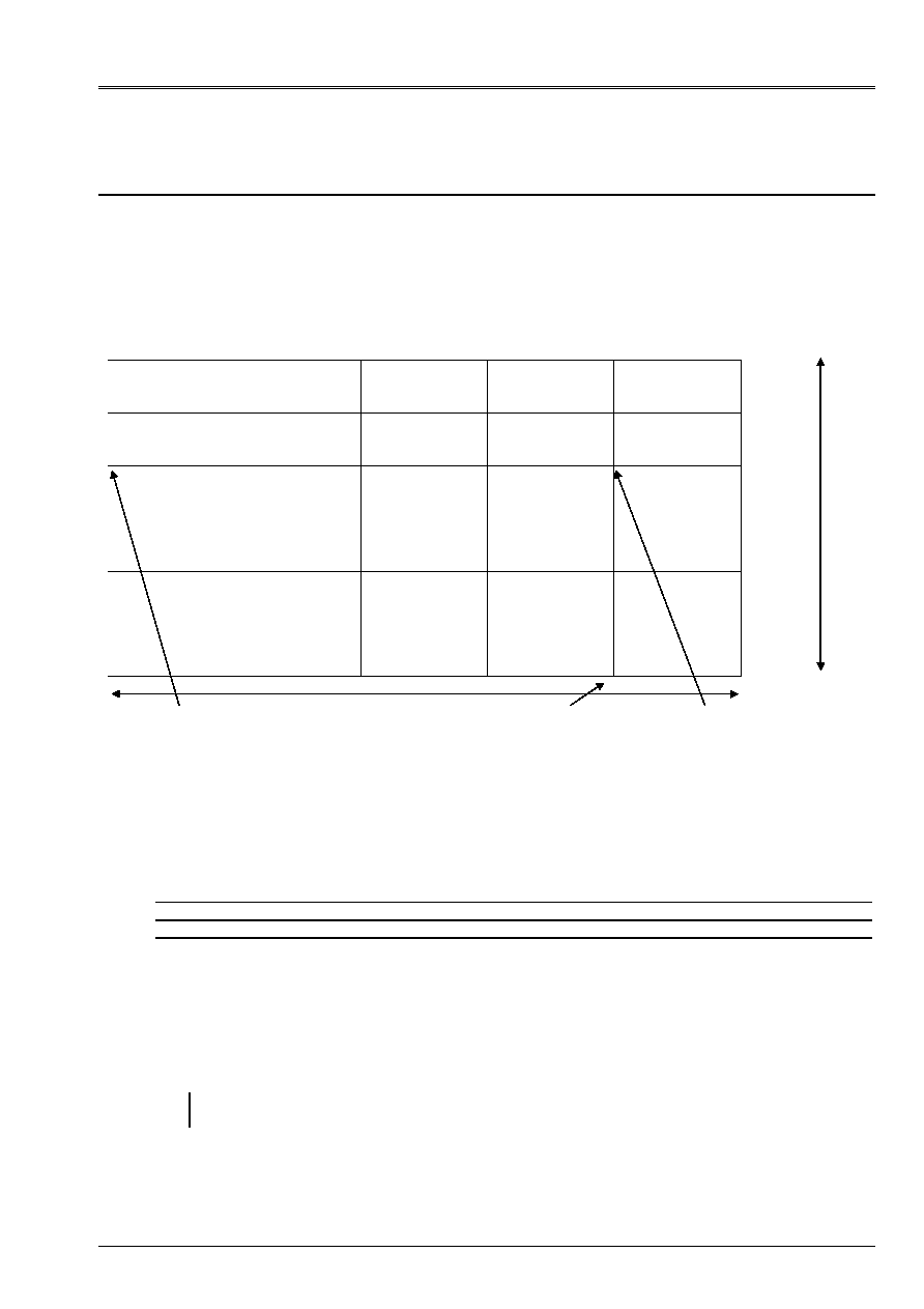
In the case 2D, the principle is identical with a very broad supposed bar which one does not modelize
that a vertical section (see diagram).
Section case 3D:
Section case 2D:
1.2 Properties
materials
Bar: concrete
Density:
2400 kg.m
3
Young modulus:
3,6.10
10
AP
Poisson's ratio: 0,48
Imposed displacement
section
Elastic solid
Surface absorbing
X
Z
y
Z
Code_Aster
®
Version
5.0
Titrate:
SDLV120 Absorption of a wave of compression in an elastic bar
Date:
09/10/01
Author (S):
G. DEVESA, V. TO MOW
Key
:
V2.04.120-A
Page:
3/8
Manual of Validation
V2.04 booklet: Linear dynamics of the voluminal structures
HT-62/01/012/A
1.3
Boundary conditions and loadings
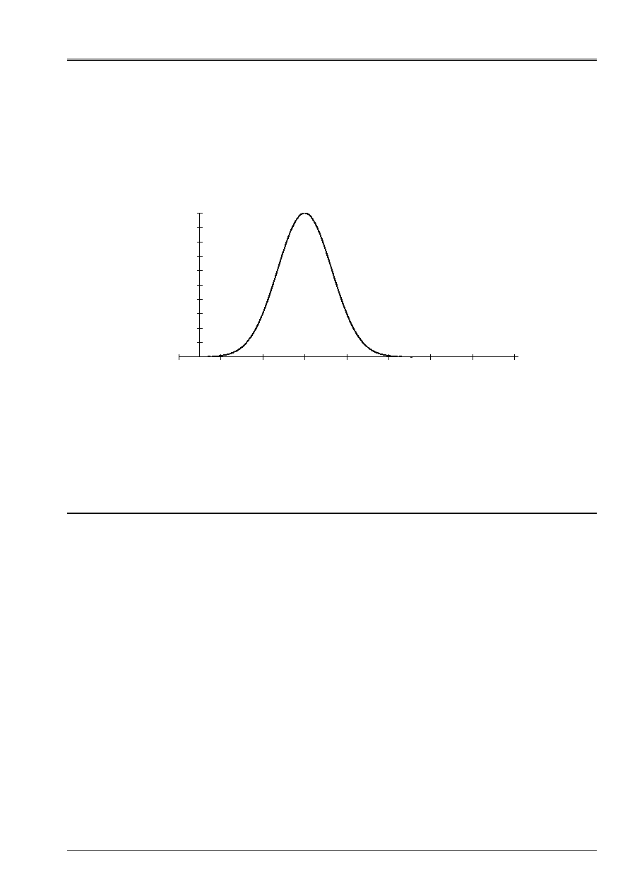
One imposes on all the nodes of the face of the piston in contact with the fluid a displacement according to X
with the function of following temporal excitation:
Displacement of the piston according to X
0,00E+00
1,00E-01
2,00E-01
3,00E-01
4,00E-01
5,00E-01
6,00E-01
7,00E-01
8,00E-01
9,00E-01
1,00E+00
- 0,1
0,1
0,3
0,5
0,7
0,9
1,1
1,3
1,5
Time (S)
Displacement (m)
1.4 Conditions
initial
Displacement is null in all the bar at the initial moment.
2
Reference solution
The solution must show the absorption of a wave of compression by absorbing surface.
imposed displacement is a uniform translation according to the axis of
X
. One must obtain a field of
identical displacement according to this direction in all the plans
X
= Cte. Moreover, the border
absorbing is orthogonal with this axis. One thus studies the absorption of plane waves of compression
under normal angle of attack. The theory [bib1] known as that with a solid paraxial border of command 0, this
absorption is perfect. It is what one must check with this reference solution.
One thus goes, by observing the evolution of displacement in a given point of the mesh, to stick to
to find in the signal obtained the duration of excitation and the return at rest after the passage of the wave,
characteristic of its absorption.
2.1
Results of reference
One gives in this paragraph the results obtained with Code_Aster in this configuration. One
check that they are satisfactory and one takes them as reference for the future.
They concern, for the case 3D, the bar being 200 m length, the evolution of displacement in X
in a point of the bar located at 150 m of the face excited in the direction
X
and in the center of the section
in the plan
yz
. For the case 2D, the bar being 50 m length, the point is located at 40 m of
face according to
X
and in the middle of the section in the direction
y
(in 2D, one takes a shorter mesh and
refined).
10
- 3
Code_Aster
®
Version
5.0
Titrate:
SDLV120 Absorption of a wave of compression in an elastic bar
Date:
09/10/01
Author (S):
G. DEVESA, V. TO MOW
Key
:
V2.04.120-A
Page:
4/8
Manual of Validation
V2.04 booklet: Linear dynamics of the voluminal structures
HT-62/01/012/A
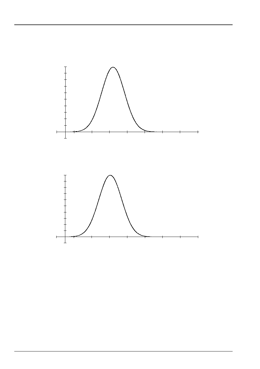
Displacement in X in the bar - case 3D
- 1,00E-04
0,00E+00
1,00E-04
2,00E-04
3,00E-04
4,00E-04
5,00E-04
6,00E-04
7,00E-04
8,00E-04
9,00E-04
1,00E-03
- 1,00E-01 1,00E-01 3,00E-01 5,00E-01 7,00E-01 9,00E-01 1,10E+00 1,30E+00 1,50E+00
Time (S)
Displacement (m)
Displacement in the bar - case 2D
- 1,00E-04
0,00E+00
1,00E-04
2,00E-04
3,00E-04
4,00E-04
5,00E-04
6,00E-04
7,00E-04
8,00E-04
9,00E-04
1,00E-03
- 1,00E-01 1,00E-01 3,00E-01 5,00E-01 7,00E-01 9,00E-01 1,10E+00 1,30E+00 1,50E+00
Time (S)
Displacement (m)
As envisaged, the width of the signal measured in both cases is identical to that of the function
of excitation. Physically, one observes the wave propagation well of compression. The signal is
little modified in its propagation and one thus finds well the maximum amplitude of 1 Misters One notes
also clearly the return at rest immediately after the passage of the wave and the absence of
signal thought of the end of the mesh.
2.2 Uncertainties
It is about a numerical result of the study. The qualitative forecasts are found. Values
numerical are related to the precision of calculation. Only the return at rest is precisely given by
analysis.
2.3 References
bibliographical
[1]
H. MODARESSI “numerical Modeling of the wave propagation in the mediums
porous rubber bands. “ Thesis doctor-engineer, Central School of Paris (1987).
Code_Aster
®
Version
5.0
Titrate:
SDLV120 Absorption of a wave of compression in an elastic bar
Date:
09/10/01
Author (S):
G. DEVESA, V. TO MOW
Key
:
V2.04.120-A
Page:
5/8
Manual of Validation
V2.04 booklet: Linear dynamics of the voluminal structures
HT-62/01/012/A
3
Modeling a: case 3D
3.1
Characteristics of modeling
Bar: PHENOMENON: “MECHANICAL”
MODELING: “3D”
3.2 Characteristics
mesh
3.3 Functionalities
tested
Controls
AFFE_MODELE AFFE
MODELING
3d_ABSO
DYNA_LINE_TRAN
DYNA_NON_LINE
3.4 Values
tested
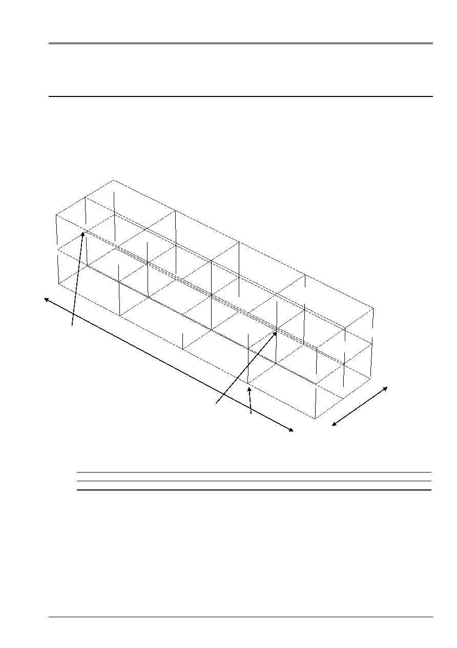
One tests the values of displacement in
X
with nodes 16, 18 and 43 (see mesh). For node 16,
one tests the maximum and the return at rest. For nodes 18 and 43, one tests the maximum.
200 m
50 m
A number of nodes: 45
A number of meshs and types: 16 HEXA8
8 QUA4 (faces of HEXA8)
Node 16
Node 18
Node 43

Code_Aster
®
Version
5.0
Titrate:
SDLV120 Absorption of a wave of compression in an elastic bar
Date:
09/10/01
Author (S):
G. DEVESA, V. TO MOW
Key
:
V2.04.120-A
Page:
6/8
Manual of Validation
V2.04 booklet: Linear dynamics of the voluminal structures
HT-62/01/012/A
·
DYNA_LINE_TRAN
:
Node
Moment (S)
Calculation with
Code_Aster
(displacement
in m)
Results of
reference
(
displacement
in m)
Variations reference -
calculation with
Code_Aster (%)
N16 5.39500E-01
9.91869E-04
1.00000E-03 0.81
RELATIVE
1.20000E+00
1.7E-8
0. 1.7E-6
ABSOLUTE
N18 5.40000E-01
9.91393E-04
1.00000E-03 0.86
RELATIVE
N43 5.00000E-01
1.00000E-03
1.00000E-03 0.
RELATIVE
·
DYNA_NON_LINE
:
Node
Moment (S)
Calculation with
Code_Aster
(displacement
in m)
Results of
reference
(
displacement
in m)
Variations reference -
calculation with
Code_Aster (%)
N16 5.40000E-01
9.92640E-04
9.92640E-04 0.74
RELATIVE
1.20000E+00
3.0E-8
0. 3.0E-6
ABSOLUTE
N18 5.40000E-01
9.92182E-04
9.92182E-04 0.78
RELATIVE
N43 5.00000E-01
1.00000E-03
1.00000E-03 0.
RELATIVE
3.5 Parameters
of execution
Version: 5.2.16
Machine: SGI ORIGIN 2000
Time CPU: 600
Memory: 64 Mo
Code_Aster
®
Version
5.0
Titrate:
SDLV120 Absorption of a wave of compression in an elastic bar
Date:
09/10/01
Author (S):
G. DEVESA, V. TO MOW
Key
:
V2.04.120-A
Page:
7/8
Manual of Validation
V2.04 booklet: Linear dynamics of the voluminal structures
HT-62/01/012/A
4
Modeling b: case 2D
4.1
Characteristics of modeling
Bar:
PHENOMENON: 'MECHANICAL
'
MODELING: 'D_PLAN
'
4.2 Characteristics
mesh
A number of nodes: 36
A number of meshs and types: 30 QUA4
12 SEG2 (faces of QUA4)
4.3 Functionalities
tested
Controls
AFFE_MODELE AFFE
MODELING
D_PLAN_ABSO
DYNA_LINE_TRAN
DYNA_NON_LINE
4.4 Values
tested
One tests the values of displacement in
X
with nodes 32, 14 and 3 (see mesh). For node 32,
one tests the maximum and the return at rest. For nodes 14 and 3, one tests the maximum.
Note:
Node 3 is on vis-a-vis imposed displacement. One thus has exactly the values of excitation
in this point.
25 m
50 m
Node 32
Node 14
Node 3

Code_Aster
®
Version
5.0
Titrate:
SDLV120 Absorption of a wave of compression in an elastic bar
Date:
09/10/01
Author (S):
G. DEVESA, V. TO MOW
Key
:
V2.04.120-A
Page:
8/8
Manual of Validation
V2.04 booklet: Linear dynamics of the voluminal structures
HT-62/01/012/A
·
DYNA_LINE_TRAN
:
Node
Moment (S)
Calculation with
Code_Aster
(displacement
in m)
Results of
reference
(
displacement in m)
Variations reference -
calculation with
Code_Aster (%)
N32 5.09500E-01
9.99536E-04 1.00000E-03 0.046
RELATIVE
1.20000E+00
6.3E-10
0.
6.3E-8
ABSOLUTE
N14 5.09500E-01
9.99536E-04 1.00000E-03 0.046
RELATIVE
N3 5.00000E-01
1.00000E-03 1.00000E-03 0.
RELATIVE
·
DYNA_NON_LINE
:
Node
Moment (S)
Calculation with
Code_Aster
(displacement
in m)
Results of
reference
(
displacement in m)
Variations reference -
calculation with
Code_Aster (%)
N32 5.09500E-01
9.99867E-04 9.99867E-04 0.013
RELATIVE
1.20000E+00
- 3.8E-9
0.
3.8E-7
ABSOLUTE
N14 5.09500E-01
9.99867E-04 9.99867E-04 0.013
RELATIVE
N3 5.00000E-01
1.00000E-03 1.00000E-03 0.
RELATIVE
4.5 Parameters
of execution
Version: 5.2.16
Machine: SGI ORIGIN 2000
Time CPU: 1200
Memory: 300 Mo
5
Summary of the results
One finds by calculation with two modelings quantitatively, the maximum of displacement
equal to the maximum amplitude of the signal and qualitatively, the return at rest after the passage of
the wave.
Results obtained with the operators
DYNA_LINE_TRAN
and
DYNA_NON_LINE
are very close.
The difference comes from obtaining to each pitch in time from the state from balance from the efforts from the second
member with the operator
DYNA_NON_LINE
, which explains why its results are a little bit
better even with a pitch of larger time. This difference remains however tiny because the pitch
time used with
DYNA_LINE_TRAN
is sufficiently small.