
Code_Aster
®
Version
5.0
Titrate:
SDLV121 Onde planes shearing in an elastic column
Date:
09/10/01
Author (S):
G. DEVESA, V. TO MOW
Key
:
V2.04.121-A
Page:
1/8
Manual of Validation
V2.04 booklet: Linear dynamics of the voluminal structures
HT-62/01/012/A
Organization (S):
EDF/RNE/AMV
Manual of Validation
V2.04 booklet: Linear dynamics of the voluminal structures
Document: V2.04.121
SDLV121 - Wave planes shearing in one
elastic column
Summary
One tests the application of a loading in transient in the form of a plane wave thanks to the elements
paraxial rubber bands of command 0, in 3D and 2D. One applies this loading to an elastic solid mass occupying one
half space and which one modelizes a column. This column is supposed to be infinite in its lower part and
level in its part higher than the level of the surface of the free half space left. One observes
propagation of the incidental wave, its reflection on the free face of the solid mass and its absorption by the elements
paraxial at the lower end of the column.
One tests successively the two direct transitory operators of Code_Aster, namely
DYNA_LINE_TRAN
and
DYNA_NON_LINE
.
Code_Aster
®
Version
5.0
Titrate:
SDLV121 Onde planes shearing in an elastic column
Date:
09/10/01
Author (S):
G. DEVESA, V. TO MOW
Key
:
V2.04.121-A
Page:
2/8
Manual of Validation
V2.04 booklet: Linear dynamics of the voluminal structures
HT-62/01/012/A
1
Problem of reference
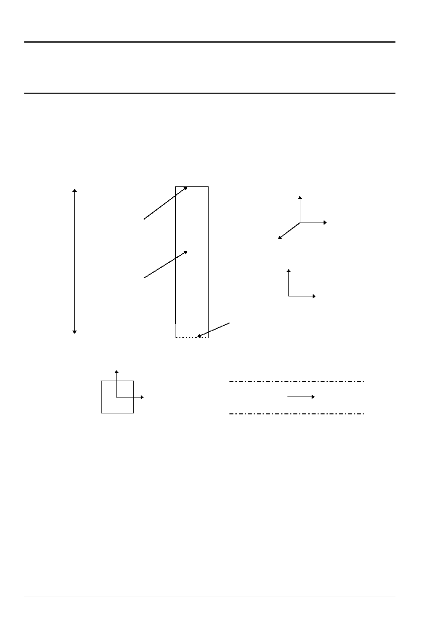
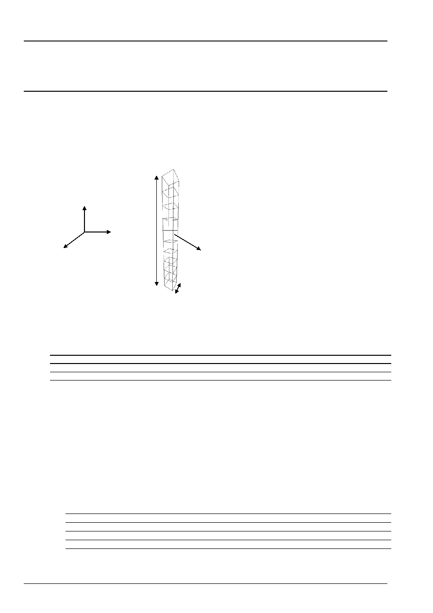
1.1 Geometry
The system considered in the case 3D is that of a homogeneous elastic ground occupying the half space
Z < 0. The plan Z = 0 is left free. One modelizes of this ground a vertical column, presumedly infinite in
its lower part and levelling than the free face at its higher end. The elements are placed
paraxial on lower surface, to translate the infinite character of the column and to apply it
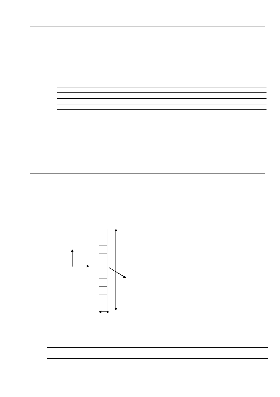
loading by plane wave. In the case 2D, the principle is identical, with a very broad column
which one modelizes only one vertical section (see diagram).
Moreover, the direction of vibration is the y axis in the case 3D. It is about the x axis in the case 2D.
Free face
(Z = 0)
Elastic solid
Paraxial surface
X
Z
y
X
y
Identify:
Case 3D
Case 2D
X
y
y
50 m
Section case 3D:
Section case 2D:
1.2 Properties
materials
Elastic solid mass: floor covering
Density:
1900 kg.m
3
Young modulus:
4,44.10
8
AP
Poisson's ratio:
0,2
1.3
Boundary conditions and loadings
One is interested in the movement 1D of the column under the exiting action of a wave planes vertical.
To identify this movement, one forces all the nodes of the same horizontal section to have it
even displacement.
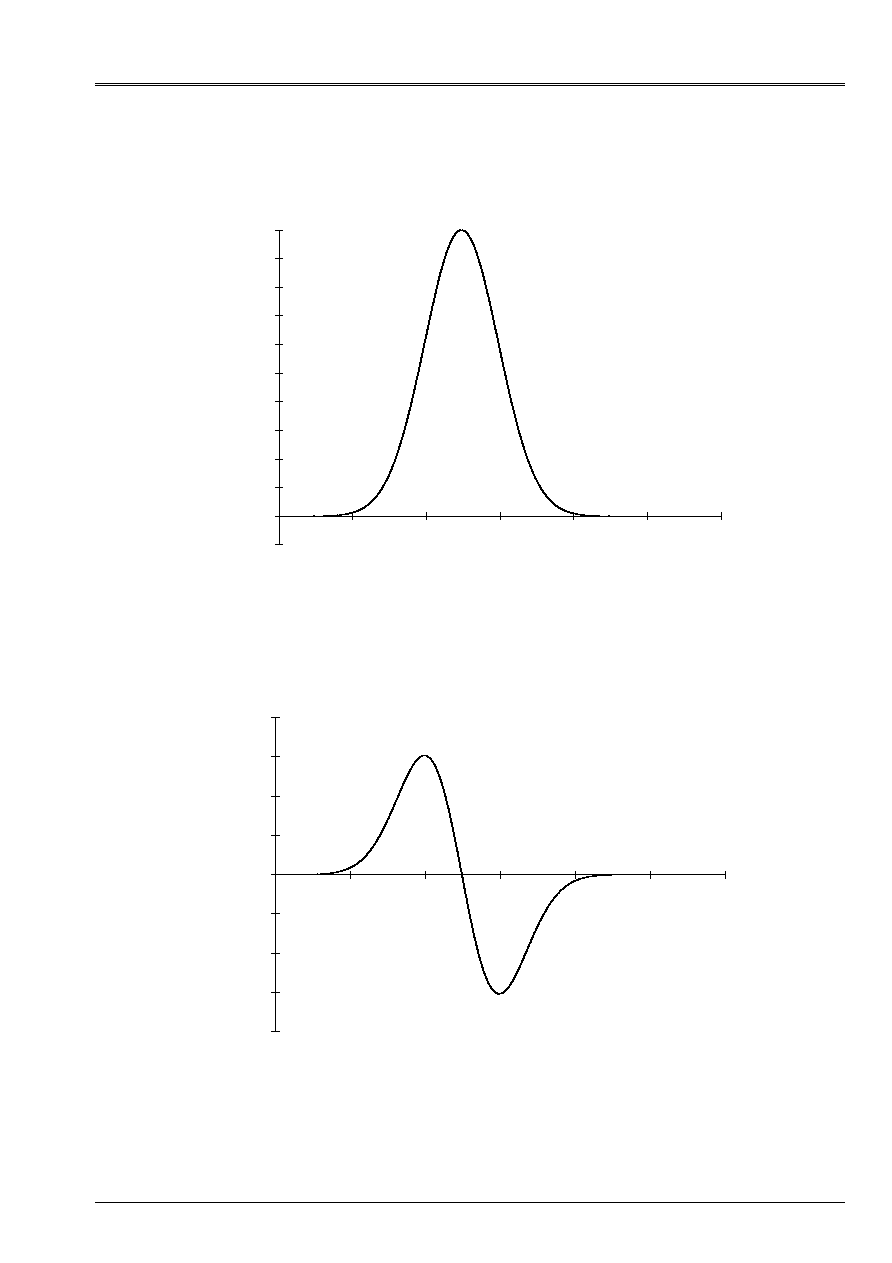
In this configuration, the loading by plane wave comprises the following characteristics:
Direction: (0. 0. 1. )
Type_d' wave: “HS”
Outdistance initial origin: 150 m
Signal: function given below (with its derivative which is used as input with calculation):
Code_Aster
®
Version
5.0
Titrate:
SDLV121 Onde planes shearing in an elastic column
Date:
09/10/01
Author (S):
G. DEVESA, V. TO MOW
Key
:
V2.04.121-A
Page:
3/8
Manual of Validation
V2.04 booklet: Linear dynamics of the voluminal structures
HT-62/01/012/A
Signal of the incidental wave
- 1,00E-04
0,00E+00
1,00E-04
2,00E-04
3,00E-04
4,00E-04
5,00E-04
6,00E-04
7,00E-04
8,00E-04
9,00E-04
1,00E-03
0,00E+00
2,00E+01
4,00E+01
6,00E+01
8,00E+01
1,00E+02
1,20E+02
length in the direction of the wave (m)
Tranversal displacement (m)
The maximum is obtained for a value of 49,5 m of the parameter.
Derived from the signal
- 8,00E-05
- 6,00E-05
- 4,00E-05
- 2,00E-05
0,00E+00
2,00E-05
4,00E-05
6,00E-05
8,00E-05
0,00E+00
2,00E+01
4,00E+01
6,00E+01
8,00E+01
1,00E+02
1,20E+02
Length in the direction of the wave (m)
Derived (without dimension)
1.4 Conditions
initial
Displacement is null in all the column at the initial moment.
Code_Aster
®
Version
5.0
Titrate:
SDLV121 Onde planes shearing in an elastic column
Date:
09/10/01
Author (S):
G. DEVESA, V. TO MOW
Key
:
V2.04.121-A
Page:
4/8
Manual of Validation
V2.04 booklet: Linear dynamics of the voluminal structures
HT-62/01/012/A
2
Reference solution
The propagation 1D of the signal of the incidental wave in the column is known analytically [bib1]. One
can for example determine the moment of passage of the maximum of the incidental wave with middle height, that is to say with
a 25 m depth, and that of the maximum of the wave thought of the same point.
Taking into account the signal given previously and position of its source to Z = 150 m, the maximum
signal is Z = 105.5 m (i.e. 150 - value of 49,5 m of the parameter corresponding) that is to say
to 50,5 m of the paraxial surface (Z = - 50 m) of the column in direction Z (that of the wave) with
the initial moment. To arrive to 25 m, it will thus have to traverse 75,5 Mr. the speed of the waves of
shearing being of 281 Mr. S
1
for the ground considered, one can thus await the maximum of
displacement with middle height in the column for time 0,27 S. Moreover, at the time of the passage of the wave
reflected, the signal will have traversed 50 m moreover, therefore one can await it for time 0,44 S. the value
maximum measured at these moments must be 1 Misters Ce are these analytical values which one will test
in calculation.
2.1
Results of reference
One gives in this paragraph the results obtained with Code_Aster in this configuration. One
check that they are satisfactory qualitatively and quantitatively.
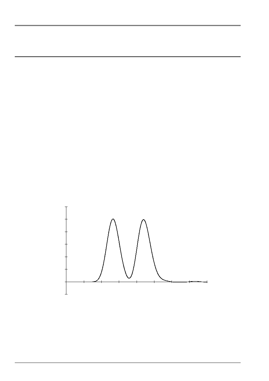
They concern, for the case 3D, the evolution of displacement in the three directions in a point of
column located at middle height, is to 25 m of the free face in direction Z. The measurement of
displacement is identical in the case 2D.
Moreover, the direction of vibration is the y axis in the case 3D. It is about the x axis in the case 2D.
Transverse displacement in the column - case 3D
- 2,00E-04
0,00E+00
2,00E-04
4,00E-04
6,00E-04
8,00E-04
1,00E-03
1,20E-03
0,00E+00 1,00E-01 2,00E-01 3,00E-01 4,00E-01 5,00E-01 6,00E-01 7,00E-01 8,00E-01
Time (S)
Displacement according to y (m)
Code_Aster
®
Version
5.0
Titrate:
SDLV121 Onde planes shearing in an elastic column
Date:
09/10/01
Author (S):
G. DEVESA, V. TO MOW
Key
:
V2.04.121-A
Page:
5/8
Manual of Validation
V2.04 booklet: Linear dynamics of the voluminal structures
HT-62/01/012/A
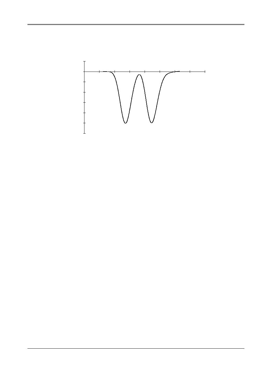
Transverse displacement in the column - case 2D
- 1,20E-03
- 1,00E-03
- 8,00E-04
- 6,00E-04
- 4,00E-04
- 2,00E-04
0,00E+00
2,00E-04
0,00E+0
0
1,00E-
01
2,00E-
01
3,00E-
01
4,00E-
01
5,00E-
01
6,00E-
01
7,00E-
01
8,00E-
01
Time (S)
Displacement (m)
It is checked first of all that displacements is null according to X and Z in the case 3D and according to y in the case
2D.
The celerity of the waves of shearing in a floor covering is 280 Mr. S
1
approximately. The length of
signal is approximately 80 m. It is thus checked that the width of the peaks is well 0,3 S at the base.
One also observes at the moments envisaged the presence of the two identical peaks due to the reflection
without change of sign on the free face. Their amplitude of 1 mm also finds the signal
imposed.
The inversion of the sign of displacement in the case 2D is due only to the orientation of the reference mark.
2.2 Uncertainties
It is about a numerical result of the study. One finds the qualitative and quantitative forecasts.
numerical values are related to the precision of calculation.
2.3 References
bibliographical
[1]
H. MODARESSI “numerical Modeling of the wave propagation in the mediums
porous rubber bands. “ Thesis doctor-engineer, Central School of Paris (1987)
Code_Aster
®
Version
5.0
Titrate:
SDLV121 Onde planes shearing in an elastic column
Date:
09/10/01
Author (S):
G. DEVESA, V. TO MOW
Key
:
V2.04.121-A
Page:
6/8
Manual of Validation
V2.04 booklet: Linear dynamics of the voluminal structures
HT-62/01/012/A
3
Modeling a: case 3D
3.1
Characteristics of modeling
Bar:
PHENOMENON: 'MECHANICAL
'
MODELING: '3D
'
3.2 Characteristics
mesh
3.3 Functionalities
tested
Controls
AFFE_MODELE AFFE MODELING
3d_ABSO
AFFE_CHAR_MECA_F ONDE_PLANE
DYNA_LINE_TRAN
DYNA_NON_LINE
3.4 Values
tested
One tests the values of displacement in the three directions with the node 22 (see mesh). For
direction y, one tests the value of the two maximum ones and the return at rest after the passage of the wave. For
the two other directions, one tests the nullity of displacement, for example at the moment of the first
maximum in Y.
·
DYNA_LINE_TRAN
:
Direction Moment
(S) Calculation with
Code_Aster
(displacement
in m)
Results of
reference
(
displacement
in m)
Variations reference -
calculation with
Code_Aster (%)
Y 2.65600E01
1.00410E03
1.E03 0.41
RELATIVE
4.38400E01
9.94716E04
1.E03 0.53
RELATIVE
8.00000E01
- 5.8E6
0. 5.8E4
ABSOLUTE
X 2.65600E01 0.
0.
0.
ABSOLUTE
Z 2.65600E01 0.
0.
0.
ABSOLUTE
·
Not measurement of
displacement (node 22)
50 m
5 m
X
Z
y
A number of nodes: 44
A number of meshs and types: 10 HEXA8
2 QUA4 (faces
HEXA8)
Code_Aster
®
Version
5.0
Titrate:
SDLV121 Onde planes shearing in an elastic column
Date:
09/10/01
Author (S):
G. DEVESA, V. TO MOW
Key
:
V2.04.121-A
Page:
7/8
Manual of Validation
V2.04 booklet: Linear dynamics of the voluminal structures
HT-62/01/012/A
·
DYNA_NON_LINE
:
Direction Moment
(S) Calculation with
Code_Aster
(displacement
in m)
Results of
reference
(
displacement in
m)
Variations reference -
calculation with
Code_Aster (%)
Y 2.67200E01
1.00396E04
1.E03 0.40
RELATIVE
4.40000E01
9.94928E04
1.E03 0.51
RELATIVE
7.20000E01
5.1E6
0. 5.1E4
ABSOLUTE
X 2.67200E01 0.
0.
0.
ABSOLUTE
Z 2.67200E01 0.
0.
0.
ABSOLUTE
3.5 Parameters
of execution
Version:
5.2.16
Machine:
SGI ORIGIN 2000
Time CPU:
300
Memory:
64 Mo
4
Modeling b: case 2D
4.1
Characteristics of modeling
Bar:
PHENOMENON: 'MECHANICAL
'
MODELING: 'D_PLAN
'
4.2 Characteristics
mesh
4.3 Functionalities
tested
Controls
AFFE_MODELE AFFE
MODELING
D_PLAN_ABSO
AFFE_CHAR_MECA_F ONDE_PLANE
DYNA_LINE_TRAN
DYNA_NON_LINE
50 m
·
Not measurement of
displacement (node 11)
y
X
A number of nodes: 22
A number of meshs and types: 10 QUA4
2 SEG2 (faces of QUA4)
5 m

Code_Aster
®
Version
5.0
Titrate:
SDLV121 Onde planes shearing in an elastic column
Date:
09/10/01
Author (S):
G. DEVESA, V. TO MOW
Key
:
V2.04.121-A
Page:
8/8
Manual of Validation
V2.04 booklet: Linear dynamics of the voluminal structures
HT-62/01/012/A
4.4 Values
tested
One tests the values of displacement in the three directions with node 11 (see mesh). For
direction X, one tests the value of the two maximum ones and the return at rest after the passage of the wave. For
the direction y, one tests the nullity of displacement, for example at the moment of the first maximum in Y.
·
DYNA_LINE_TRAN
:
Direction Moment
(S) Calculation with
Code_Aster
(displacement
in m)
Results of
reference
(
displacement
in m)
Variations reference -
calculation with
Code_Aster (%)
X 2.65600E01
1.00410E04
1.E03 0.41
RELATIVE
4.38400E01
9.94716E04
1.E03 0.53
RELATIVE
8.00000E01
5.8E6
0. 5.8E4
ABSOLUTE
Y 2.65600E01 0.
0.
0.
ABSOLUTE
·
DYNA_NON_LINE
:
Direction Moment
(S) Calculation with
Code_Aster
(displacement
in m)
Results of
reference
(
displacement
in m)
Variations reference -
calculation with
Code_Aster (%)
X 2.65600E01
1.00319E03
1.E03 0.32
RELATIVE
4.38400E01
9.93554E04
1.E03 0.64
RELATIVE
8.00000E01
3.0E6
0. 3.0E4
ABSOLUTE
Y 2.65600E01 0.
0.
0.
ABSOLUTE
4.5 Parameters
of execution
Version:
5.2.16
Machine:
SGI ORIGIN 2000
Time CPU:
300
Memory:
64 Mo
5
Summary of the results
One finds by calculation with two modelings quantitatively, the values of maximum of
displacement equal to the maximum amplitude of the signal and the values of the corresponding moments and
qualitatively, the return at rest after the passage of the considered wave.
Results obtained with the operators
DYNA_LINE_TRAN
and
DYNA_NON_LINE
are very close.
The difference comes from obtaining to each pitch in time from the state from balance from the efforts from the second
member with the operator
DYNA_NON_LINE
, which explains why its results are in general small
not very better even with a pitch larger time. This difference remains however tiny because it
no the time used with
DYNA_LINE_TRAN
is sufficiently small.