
Code_Aster
®
Version
4.0
Titrate:
SHLL101 right Beam. Analyze harmonic
Date:
01/09/99
Author (S):
B. QUINNEZ, G. DEVESA
Key:
V2.06.101-B
Page:
1/8
Manual of Validation
V2.06 booklet: Harmonic response of the linear structures
HI-75/98/040 - Ind A
Organization (S):
EDF/IMA/MN, EP/AMV
Manual of Validation
V2.06 booklet: Harmonic response of the linear structures
Document: V2.06.101
SHLL101 - Right beam. Analyze harmonic
Summary:
This two-dimensional problem consists in calculating the efforts present in a beam subjected to a traction or
with a bending during a harmonic analysis. The reference solution is obtained starting from the equations
discretized.
This test comprises two modelings.
For the first modeling, four stresses are tested:
·
force traction,
·
force traction and material presenting a damping,
·
flexural strength,
·
flexural strength and material presenting a damping.
For the second modeling, two stresses are tested:
·
force traction,
·
force traction and material presenting a damping.
The second modeling makes it possible to test the complex loadings imposed by the control
AFFE_CHAR_MECA_C
.
Code_Aster
®
Version
4.0
Titrate:
SHLL101 right Beam. Analyze harmonic
Date:
01/09/99
Author (S):
B. QUINNEZ, G. DEVESA
Key:
V2.06.101-B
Page:
2/8
Manual of Validation
V2.06 booklet: Harmonic response of the linear structures
HI-75/98/040 - Ind A
1
Problem of reference
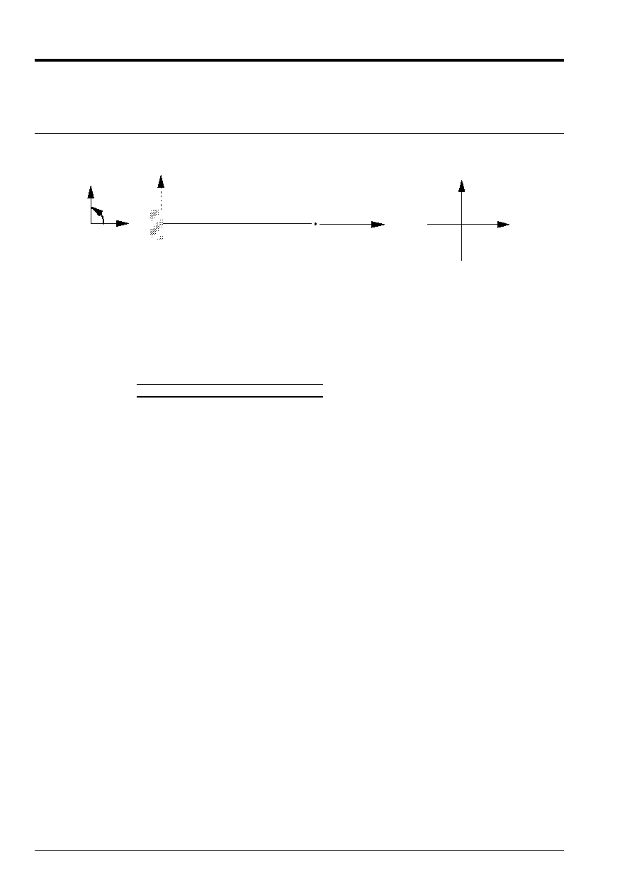
1.1 Geometry
With
y
B
X
Z
y
y, v
X, U
The geometrical characteristics of the beam constituting the mechanical model are as follows:
Length: L = 10 m
Cross section
Surface
IZ = IY
JX
3.439 10
3
m
2
1.377 10
5
m
4
2.754 10
5
m
4
The co-ordinates (in meters) of the points characteristic of the beam are:
With
B
X
0.
10.
y
0.
0.
1.2
Material properties
The properties of material constituting the beam are:
E = 1.658 10
10
AP
= 0.3
= 1.3404106 10
4
kg/m
3
= Amor_alpha = 0.001
= Amor_beta = 0.
1.3
Boundary conditions and loadings
The boundary condition which characterizes this problem is the embedding of point A and is written:
U = v = 0.
= 0.
For the loading one a:
Fx = 3000. NR
Fy = Fz = 0.
(tensile load)
Fx = 0.
Fy = 3000. NR
Fz = 0.
(bending load)

Code_Aster
®
Version
4.0
Titrate:
SHLL101 right Beam. Analyze harmonic
Date:
01/09/99
Author (S):
B. QUINNEZ, G. DEVESA
Key:
V2.06.101-B
Page:
3/8
Manual of Validation
V2.06 booklet: Harmonic response of the linear structures
HI-75/98/040 - Ind A
2
Reference solution
2.1
Method of calculation used for the reference solution
If the beam is modelized by a beam of Euler-Bernoulli and only one finite element, the problem
harmonic can be written in the following way:
problem in traction:
(
)
()
()
()
()
()
1
6
6
2
2
+
-
=
=
-
+
I
ES
L U B
SSL U B F B
U B
F B
ES
L
SSL
I
ES
L
X
from where
problem in bending:
(
)
()
()
()
-
-
-
+ +
-
-
=
2
2
2
3
3
2
13
35
11
210
11
210
105
1
12
1
2
2
3
0
L
L
L
L
I
E I
L
L
L
L
v B
B
F B
y
y
Note:
If the material does not present damping, one has then: Amor_alpha =
= 0.
The efforts at the point B are calculated in the following way:
problem in traction:
()
()
NR B
ES
L
SSL U B
=
-
2
6
problem in bending:
()
()
()
()
VY B
MFZ B
L
L
L
L
E I
L
L
L
L
v B
B
y
= -
-
-
+
-
-
2
2
2
3
3
2
13
35
11
210
11
210
105
12
1
2
2
3
One analytically solves the systems 2 X 2 to obtain the solution.
2.2
Results of reference
The results of reference are displacements, speeds, accelerations and the efforts
generalized obtained at the point B during the harmonic analysis.
2.3
Notice for modeling B
For modeling B, one wants to test the problem in traction in the case of the key word
FORCE_POUTRE
who allows to apply efforts distributed. To obtain the same solution as the beam subjected to
nodal force in its end, the relation between the effort distributed constant and the nodal force is:
()
F B
F L
X
=
2
With the values given to the 1.3, one a:
F
= 600 NR/m

Code_Aster
®
Version
4.0
Titrate:
SHLL101 right Beam. Analyze harmonic
Date:
01/09/99
Author (S):
B. QUINNEZ, G. DEVESA
Key:
V2.06.101-B
Page:
4/8
Manual of Validation
V2.06 booklet: Harmonic response of the linear structures
HI-75/98/040 - Ind A
2.4
Uncertainty on the solution
If the assumptions are checked (beam of Euler-Bernoulli), the solution is analytical.
2.5 References
bibliographical
[1]
Reference material of
Code_Aster
: Elements of beams “exact” (right and
curves) - [R3.08.01].

Code_Aster
®
Version
4.0
Titrate:
SHLL101 right Beam. Analyze harmonic
Date:
01/09/99
Author (S):
B. QUINNEZ, G. DEVESA
Key:
V2.06.101-B
Page:
5/8
Manual of Validation
V2.06 booklet: Harmonic response of the linear structures
HI-75/98/040 - Ind A
3 Modeling
With
3.1
Characteristics of modeling
With
B
y, v
X, U
The beam consists of only one mesh.
The modeling used for the beam is that of Euler-Bernoulli (
POU_D_E
).
End A is embedded:
DX = DY = DZ = 0.
DRX = DRY = DRZ = 0.
3.2
Characteristics of the mesh
A number of nodes: 2
A number of meshs and types: 1 mesh of the type SEG 2
The points characteristic of the mesh are as follows:
Not A = A
Not B = B
3.3 Functionalities
tested
Controls
Keys
AFFE_CARA_ELEM
BEAM
“GENERAL”
ALL
[U4.24.01]
AFFE_CHAR_MECA
DDL_IMPO
NODE
[U4.25.01]
FORCE_NODALE
NODE
FX
FY
DEFI_MATERIAU
ELAS
E, RHO, NAKED
[U4.23.01]
AMOR_ALPHA
AMOR_BETA
CALC_MATR_ELEM
OPTION
“MASS_MECA”
[U4.41.01]
'AMOR_MECA
“RIGI_MECA”
CALC_VECT_ELEM
OPTION
“CHAR_MECA”
[U4.41.02]
DYNA_LINE_HARM
MATR_MASS
[U4.54.02]
MATR_RIGI
MATR_AMOR
EXCIT
VECT_ASSE
CALC_ELEM
OPTION
“EFGE_ELNO_DEPL”
[U4.61.02]

Code_Aster
®
Version
4.0
Titrate:
SHLL101 right Beam. Analyze harmonic
Date:
01/09/99
Author (S):
B. QUINNEZ, G. DEVESA
Key:
V2.06.101-B
Page:
6/8
Manual of Validation
V2.06 booklet: Harmonic response of the linear structures
HI-75/98/040 - Ind A
4
Results of modeling A
4.1
Values tested (reality-imaginary form)
Problem 1: traction
Not/Size
Reference
Aster
% difference
displacement
B
DX
(5.318 10
5
, 0.)
(5.318 10
5
, 0.)
0.
speed
B
DX
(0., 3.341 10
3
)
(0., 3.341 10
3
)
0.
acceleration
B
DX
( 2.099 10
1
, 0.)
( 2.099 10
1
, 0.)
0.
generalized effort
B
NR
(3000., 0.)
(3000., 0.)
0.
Problem 2: bending
Not/Size
Reference
Aster
% difference
displacement
B
DY
(1.828 10
2
, 0.)
(1.828 10
2
, 0.)
0.
DRZ (1.82 10
2
, 0.)
(1.82 10
2
, 0.)
0.
speed
B
DY
(0., 1.1489)
(0., 1.1489)
0.
DRZ (0., 1.1438)
(0., 1.1438)
0.
acceleration
B
DY
( 7.219 10
1
)
( 7.219 10
1
, 0.)
0.
DRZ ( 7.186 10
1
, 0.)
( 7.186 10
1
, 0.)
0.
generalized effort
B
VY
(3000., 0.)
(3000., 0.)
0.
MFZ (0., 0.)
( 1.164 10
10
, 0.)
0.
Problem 3: traction + damping
Not/Size
Reference
Aster
% diff
displacement
B D
X
(5.296 10
5
, 3.363 10
3
)
(5.296 10
5
, 3.363 10
3
)
0.
speed
B D
X
(2.113 10
4
, 3.327 10
3
)
(2.113 10
4
, 3.327 10
3
)
0.
acceleration
B D
X
( 2.091 10
1
, 1.327 10
2
)
( 2.091 10
1
, 1.327 10
2
)
0.
generalized effort
B NR
(2.987 10
3
, 1.8975 10
2
)
(2.987 10
3
, 1.8975 10
2
)
0.
Problem 4: bending + damping
Not/Size
Reference
Aster
%
diff
displacement
B DY
(1.746 10
2
, 4.469 10
3
)
(1.746 10
2
, 4.469 10
3
)
0.
DRZ (1.757 10
2
, 3.402 10
3
)
(1.757 10
2
, 3.402 10
3
)
0.
speed
B DY
(2.808 10
1
, 1.097)
(2.808 10
1
, 1.097)
0.
DRZ (2.138 10
1
, 1.104)
(2.138 10
1
, 1.104)
0.
acceleration
B DY
( 6.895 10
1
, 1.764 10
1
)
( 6.895 10
1
, 1.764 10
1
)
0.
DRZ ( 6.94 10
1
, 1.343 10
1
)
( 6.94 10
1
, 1.343 10
1
)
0.
generalized effort
B VY
(3.021 10
3
, 1.212 10
2
)
(3.021 10
3
, 1.212 10
2
)
0.
MFZ ( 1.567 10
2
, 8.583 10
2
)
( 1.567 10
2
, 8.583 10
2
)
0.
4.2 Parameters
of execution
Version: NEW 3.06
Machine: CRAY C90
Overall dimension memory:
8 MW
Time CPU To use:
5.9 seconds

Code_Aster
®
Version
4.0
Titrate:
SHLL101 right Beam. Analyze harmonic
Date:
01/09/99
Author (S):
B. QUINNEZ, G. DEVESA
Key:
V2.06.101-B
Page:
7/8
Manual of Validation
V2.06 booklet: Harmonic response of the linear structures
HI-75/98/040 - Ind A
5 Modeling
B
5.1
Characteristics of modeling
With
B
y, v
X, U
The beam consists of only one mesh.
The modeling used for the beam is that of Euler-Bernoulli (
POU_D_E
).
End A is embedded:
DX = DY = DZ = 0.
DRX = DRY = DRZ = 0.
5.2
Characteristics of the mesh
A number of nodes: 2
A number of meshs and types: 1 mesh of the type SEG 2
The points characteristic of the mesh are as follows:
Not A = A
Not B = B
5.3 Functionalities
tested
Controls
Keys
AFFE_CARA_ELEM
BEAM
“GENERAL”
ALL
[U4.24.01]
AFFE_CHAR_MECA_C
DDL_IMPO
NODE
[U4.25.01]
FORCE_POUTRE
NODE
FX
DEFI_MATERIAU
ELAS
E, Rho, Naked
[U4.23.01]
Amor_alpha
Amor_Beta
CALC_MATR_ELEM
OPTION
“MASS_MECA”
[U4.41.01]
'AMOR_MECA
“RIGI_MECA”
DYNA_LINE_HARM
MATR_MASS
[U4.54.02]
MATR_RIGI
MATR_AMOR
EXCIT
CHARGE
FONC_MULT_C
CALC_ELEM
OPTION
“EFGE_ELNO_DEPL”
[U4.61.02]
EXCIT
CHARGE
FONC_MULT_C

Code_Aster
®
Version
4.0
Titrate:
SHLL101 right Beam. Analyze harmonic
Date:
01/09/99
Author (S):
B. QUINNEZ, G. DEVESA
Key:
V2.06.101-B
Page:
8/8
Manual of Validation
V2.06 booklet: Harmonic response of the linear structures
HI-75/98/040 - Ind A
6
Results of modeling B
6.1
Values tested (reality-imaginary form)
Problem 1: traction (effort distributed real: null imaginary part)
Not/Size
Reference
Aster
% difference
displacement
B
DX
(5.318 10
5
, 0.)
(5.318 10
5
, 0.)
0.
speed
B
DX
(0., 3.341 10
3
)
(0., 3.3414 10
3
)
0.
acceleration
B
DX
( 2.099 10
1
, 0.)
( 2.0994 10
1
, 0.)
0.
generalized effort
B
NR
(3000., 0.)
(3000., 0.)
0.
Problem 2: traction (effort distributed complex: null rélle part)
Not/Size
Reference
Aster
% difference
displacement
B
DX
(0., 5.318 10
5
)
(0., 5.318 10
5
)
0.
speed
B
DX
(- 3.341 10
3
, 0.)
(- 3.3414 10
3
, 0.)
0.
acceleration
B
DX
(0., 2.099 10
1
)
(0., 2.0994 10
1
)
0.
generalized effort
B
NR
(0., 3000.)
(0., 3000.)
0.
Problem 3: traction + damping (effort distributed real: null imaginary part)
Not/Size
Reference
Aster
% diff
displacement
B
DX
(5.296 10
5
, 3.363 10
3
)
(5.2966 10
5
, 3.3637 10
3
)
0.
speed
B
DX
(2.113 10
4
, 3.327 10
3
)
(2.1135 10
4
, 3.3279 10
3
)
0.
acceleration
B
DX
( 2.091 10
1
, 1.327 10
2
)
( 2.091 10
1
, 1.3279 10
2
)
0.
generalized effort
B
NR
(2.9879 10
3
, 1.897 10
2
)
(2.987 10
3
, 1.8975 10
2
)
0.
Problem 4: bending + damping (effort distributed complex: null real part)
Not/Size
Reference
Aster
% diff
displacement
B
DX
(3.363 10
3
, 5.296 10
5
)
(5.296 10
5
, 3.363 10
3
)
0.
speed
B
DX
(- 3.327 10
3
, 2.113 10
4
)
(- 3.3279 10
3
, 2.1135 10
4
)
0.
acceleration
B
DX
(- 1.327 10
2
, - 2.091 10
1
)
(- 1.3279 10
2
, - 2.091 10
1
)
0.
generalized effort
B
NR
(1.897 10
2
, 2.9879 10
3
)
(1.8975 10
2
, 2.98794 10
3
)
0.
When the effort distributed is applied as an imaginary part of the loading, the reference solution is
obtained from that of real modeling A while exchanging left and imaginary part and in
changing the sign of the new real parts.
6.2 Parameters
of execution
Version: NEW 4.03
Machine: CRAY C90
Overall dimension memory:
16 MW
Time CPU To use:
7.9 seconds
7
Summary of the results
The analytical results well are found.