Code_Aster
®
Version
6.2
Titrate:
SSLL102 - Fixed beam subjected to unit efforts
Date:
20/12/02
Author (S)
:
J.M. PROIX, J. PELLET, F. LEBOUVIER
Key:
V3.01.102-D
Page:
1/18
Manual of Validation
V3.01 booklet: Linear statics of the linear structures
HT-66/02/001/A
Organization (S)
: EDF-R & D/AMA, DeltaCAD
Manual of Validation
V3.01 booklet: Linear statics of the linear structures
Document: V3.01.102
SSLL102 - Fixed beam subjected to efforts
unit
Summary:
This test allows a simple checking of calculations of right beams and hull 1D in mechanics of the structures
linear statics. The model is linear.
·
7 modelings make it possible to test the various types of elements of rectangular beams in Code_Aster.
For each modeling, one calculates simultaneously 3 beams of different sections: rectangle, circle,
angle.
Modeling A makes it possible of more than test the change of reference mark: the beam is directed according to
trisecting with the total reference mark.
Modeling E tests the loading distributed on voluminal edges of elements.
Modeling F corresponds to a loading distributed varying linearly with modeling
POU_D_E.
Modeling G corresponds to a loading distributed varying linearly with modeling
POU_D_TG.
·
Modeling H makes it possible to test the element of hull 1D (COQUE_C_PLAN) subjected to loads
unit.
·
Modeling I makes it possible to test a loading distributed varying linearly with modeling
TUYAU_3M.
The values tested are the generalized displacements, efforts and the stresses.
Code_Aster
®
Version
6.2
Titrate:
SSLL102 - Fixed beam subjected to unit efforts
Date:
20/12/02
Author (S)
:
J.M. PROIX, J. PELLET, F. LEBOUVIER
Key:
V3.01.102-D
Page:
2/18
Manual of Validation
V3.01 booklet: Linear statics of the linear structures
HT-66/02/001/A
1
Problem of reference
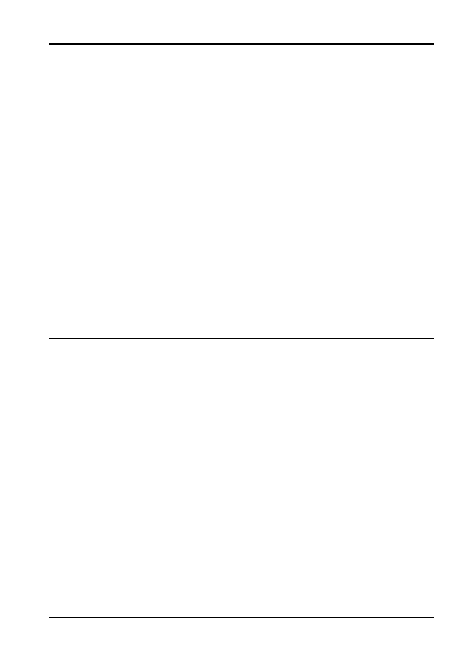
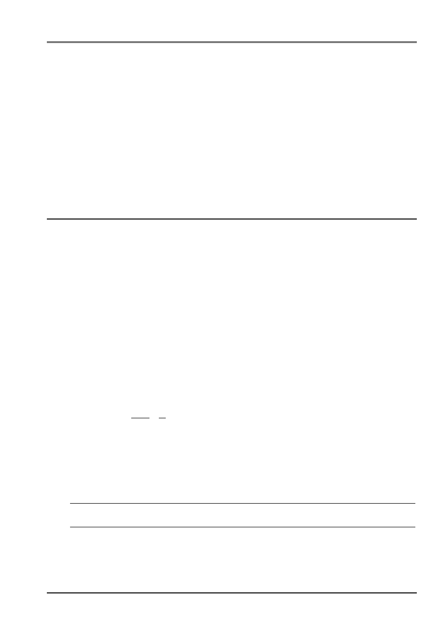
1.1 Geometry
Right beam length
L
, of direction X.
O
B
L
L = 2
y
X
Z O
One calculates simultaneously 3 types of different cross sections:
1 rectangular section
B = 0.1
= 0.2 have
1 corner section with equal wings
H = 0.12
0.12
0.008
0.008
G
Z
G
y
1 circular section
1.2
Material properties
E = 2. 10
11
AP
= 0.3
1.3
Boundary conditions and loadings
Embedding out of O
·
6 unit loadings in b:
Fx = 1
MX = 1
Fy = 1
My = 1
Fz = 1
Mz = 1
·
1 loading combined bending + traction: Fx = 1 My = 1 Mz = 1
·
1 loading combined sharp efforts + torsion: Fy = 1 Fz = 1 MX = 1
·
1 loading distributed linear: Circular Fy = 1000.x section (modelings F, G, I) (with
support simple of A and B in this case)
1.4
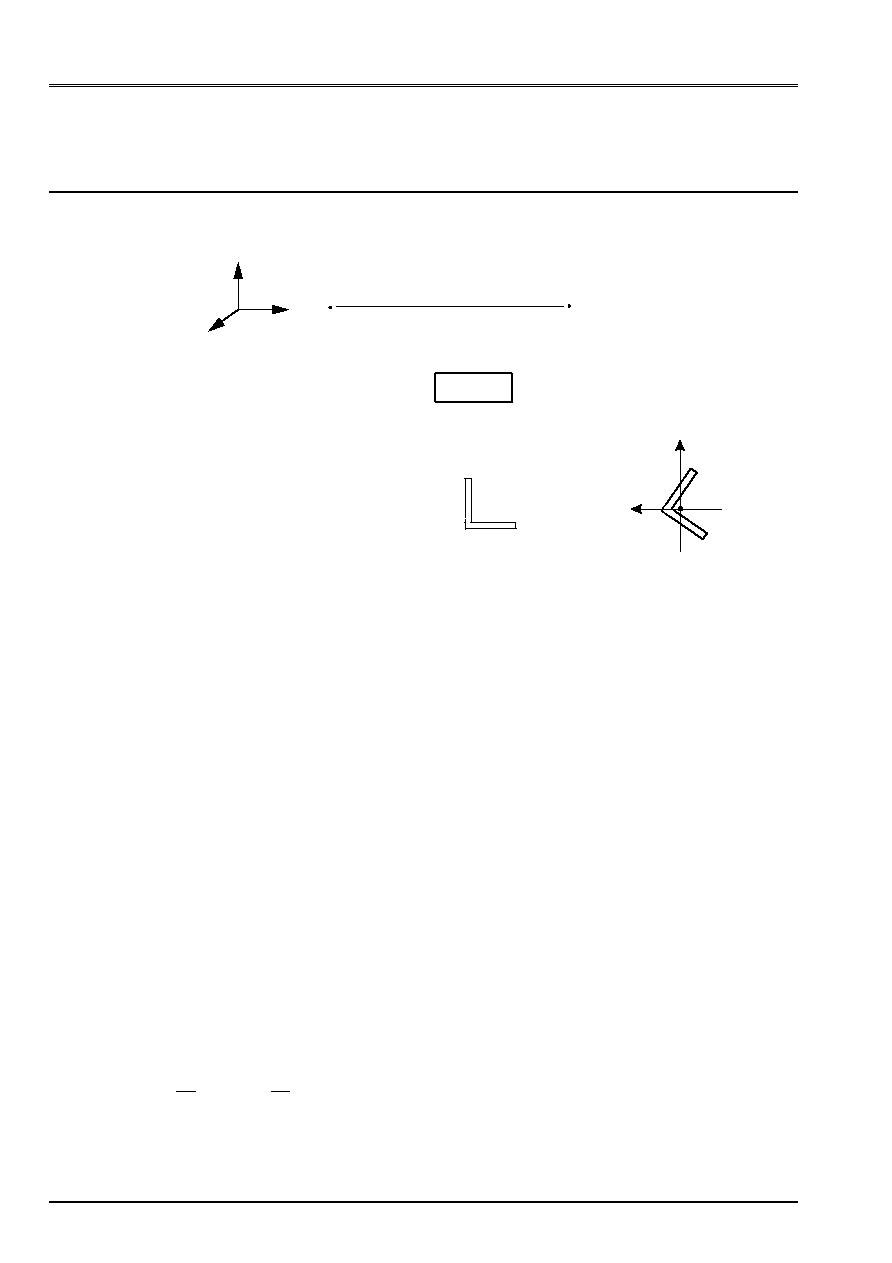
Notation of the characteristics of cross sections
The geometrical characteristics of the cross sections are noted:`
A:
surface of the section
I I
y
Z
,
:
geometrical moments of inertia compared to the main axes
of inertia of the section
JX:
constant of torsion
ay az
,
:
coefficients of shearing in the directions
Gy
and
Gz
With
With
ay
With
With
az
y
Z
'
'
=
=
and
:
equivalent reduced surfaces
E E
y
Z
,
:
eccentricity of the center of torsion
JG
:
constant of roll
Code_Aster
®
Version
6.2
Titrate:
SSLL102 - Fixed beam subjected to unit efforts
Date:
20/12/02
Author (S)
:
J.M. PROIX, J. PELLET, F. LEBOUVIER
Key:
V3.01.102-D
Page:
3/18
Manual of Validation
V3.01 booklet: Linear statics of the linear structures
HT-66/02/001/A
2
Reference solution
2.1
Method of calculation used for the reference solution
·
Analytical solution [bib1] and [bib2]: displacements out of B
()
()
Simple traction
Pure bending
Pure bending
Torsion
Pure bending
Pure bending
with
U
F L
E S
U
F L
E I
L F
E I
L F
E I
MR. L
G J
U
MR. L
E I
MR. L
E I
E I
L GA
E I
L
X
X
y
y
y
Z
Z
y
Z
y
Z
y
X
X
X
Z
y
y
y
y
y
y
y
Z
uz
L
E Iy Fz
Z
uy MzL
E Iz
Z
Mz L
E Iz
=
=
+
=
= -
=
= -
=
=
=
=
+
=
= +
3
2
2
2
2
4
12
2
2
2
12
12
3
12
4
2
2
'
2
GA
z'
Notice 1:
For the corner section, as the center of shearing is not confused with the center
of gravity
()
E
y
0
, it is necessary to add the torque:
M
F E
X
Z
y
=
.
with the loading
F
Z
=
1
This modifies displacement:
(
)
U
L
E I F
E
MR. L
G J
Z
y
Z
Z
X
y
X
X
X
=
+
+
=
3
12
4
.
.
.
In the same way, the loading
M
X
=
1
involve a displacement
U
E
Z
X
y
= +
.
.
Loading distributed linear:
()
(
)
L
X
I.E.(internal excitation)
pL
U
L
X
L
X
LEI
px
X
U
y
y
519
.
0
00652
.
0
7
10
3
360
in
4
max
4
2
2
4
=
=
+
-
=
Code_Aster
®
Version
6.2
Titrate:
SSLL102 - Fixed beam subjected to unit efforts
Date:
20/12/02
Author (S)
:
J.M. PROIX, J. PELLET, F. LEBOUVIER
Key:
V3.01.102-D
Page:
4/18
Manual of Validation
V3.01 booklet: Linear statics of the linear structures
HT-66/02/001/A
Notice 2:
With regard to modeling A, the beam is carried by the vector
E
1
1
3
1
1
1
=
.
other vectors of the local reference mark are:
E
2
1
2
1
1
0
=
-
and
E
3
1
6
1
1
2
=
-
-
The components of the vector displacement in the total reference mark are obtained by:
U
U
G
room
=
-
-
-
1
3
1
2
1
6
1
3
1
2
1
6
1
3 0
2
6
·
Generalized efforts and stresses out of O:
()
()
()
()
()
()
()
()
()
()
()
()
()
()
NR O
F
NR
S
MR. O
T L
T
F
y
M y
I
T
K S
MR. O
T L
T O
F
y
M Z
I
T
K S
MR. O
MR. B
MR. R
J
MR. O
MR. B
Z
M Z
I
MR. O
MR. B
y
M y
I
X
xx
Z
y
y
y
xx
Z
Z
xy
y
y
y
Z
Z
Z
xx
y
y
xz
Z
Z
X
X
xy
xz
X
T
X
y
y
xx
y
y
Z
Z
xx
y
Z
=
=
=
=
=
=
= -
=
= -
=
=
=
=
=
=
=
=
.
.
.
.
Loading distributed linear:
()
(
)
()
M X
L X X V
X
L
X
M
R
I
X
L
Z
y
xx
Z
Z
= -
-
= +
-
=
=
1000
6
1000
6
1000
2
3
3
2
3
2
2
max
max
.
in
2.2
Results of reference
·
Displacement of the point B,
·
efforts generalized at the point O,
·
stresses of the point O.
Code_Aster
®
Version
6.2
Titrate:
SSLL102 - Fixed beam subjected to unit efforts
Date:
20/12/02
Author (S)
:
J.M. PROIX, J. PELLET, F. LEBOUVIER
Key:
V3.01.102-D
Page:
5/18
Manual of Validation
V3.01 booklet: Linear statics of the linear structures
HT-66/02/001/A
2.3
Uncertainty on the solution
Analytical solution.
2.4 References
bibliographical
[1]
J.L. BATOZ, G. DHATT: “Modeling of the structures by finite elements” - Volume 2
ED. HERMES.
[2]
N.D. PIKLEY: “Formulated for Stress, Stain & Structural Matrices” ED. John Wiley & Sounds.
3 Modeling
With
3.1
Characteristics of modeling
2 elements
POU_D_E
K
K
y
Z
=
=
=
1
0
by type of section
S1: Rectangular section modelized by
SECTION: “GENERAL”
With
Iy
Iz
J
Ry
Rz
R
X
T
=
=
=
=
=
=
=
-
-
-
0 02
01666 10
0 6666 10
0 45776 10
01
0 05
0 0892632
4
4
4
.
.
.
.
.
.
.
(
)
Not calculation of the stresses
S2: Corner section
With
Iy
Iz
J
E
E
X
y
Z
=
=
=
=
=
=
-
-
-
-
-
1856 10
4 167339 10
1045547 10
03 9595 10
41012 10
0
3
4
4
8
3
.
.
.
.
.
.
S3: Rectangular section modelized by
SECTION: RECTANGLE
Hy
Hz
=
=
0 2
01
.
.
S4: Section
RING
R
=
01
.
I
I
R
y
Z
= =
=
-
4
4
4
4 10
.
3.2
Characteristics of the mesh
4 X 2 elements
POU_D_E
. The beam is directed according to the vector (1, 1, 1).
3.3 Functionalities
tested
Controls
AFFE_CARA_ELEM
BEAM: SECTION
“GENERAL”
“RIGHT-ANGLED”
“CIRCLE”
CALC_ELEM “EFGE_ELNO_DEPL”
“SIGM_ELNO_DEPL”
“SIPO_ELNO_DEPL”

Code_Aster
®
Version
6.2
Titrate:
SSLL102 - Fixed beam subjected to unit efforts
Date:
20/12/02
Author (S)
:
J.M. PROIX, J. PELLET, F. LEBOUVIER
Key:
V3.01.102-D
Page:
6/18
Manual of Validation
V3.01 booklet: Linear statics of the linear structures
HT-66/02/001/A
4
Results of modeling A
4.1 Values
tested
Loading case
Beam
Identification
Reference
Aster %
difference
F
X
= 1
S1 = S3 U
X
(B)
2.887 10
10
2.887
10
10
0
xx
(0)
50. 50.
0
S2
U
X
(B)
3.11 10
9
3.11
10
9
0
S4
U
X
(B)
1.838 10
10
1.838
10
10
0
xx
31.83 31.831
0
F
y
= 1
S1 = S3 U
y
(B)
+1.414 10
7
1.414
10
7
0
Z
(B)
1.225 10
7
1.225
10
7
0
xx
(0)
3000 3000
0
S2
U
y
(B)
9.017 10
8
9.017
10
8
0
S4
xx
(0)
2546.479 2546.48
0
F
Z
= 1
S1 = S3 U
Z
(B)
6.532 10
7
6.532
10
7
0
y
(B)
4.243 10
7
4.243
10
7
0
xx
(0)
6000 6000
0
xz
(0)
50 50
0
S2
U
Z
(B)
9.279 10
7
9.279
10
7
0
y
(B)
1.553 10
5
1.553 10
5
0
X
(B)
1.555 10
5
1.555
10
5
0
S4
U
Z
(B)
1.386 10
7
1.386
10
7
0
y
(B)
9 10
8
9
10
8
0
xx
(0)
2546.479 2546.479
0
xz
(0)
31.831 31.831
0
M
X
= 1
S1 = S3
X
(B)
3.279 10
7
3.279
10
7
0
xy
=
xz
(0)
1950 1950
0
S2
X
(B)
3.791 10
4
3.791
10
4
U
Z
(B)
2.199 10
5
2.199
10
5
0
S4
X
(B)
9.556 10
8
9.556
10
8
0
xy
=
xz
(0)
636.62 636.62
0
M
y
= 1
S1 = S3 U
Z
(B)
4.899 10
7
4.899
10
7
0
y
(B)
4.243 10
7
4.243
10
7
0
xx
(0)
3000 3000
0
S2
U
Z
(B)
1.959 10
8
1.959
10
8
0
y
(B)
1.697 10
8
1.697
10
8
0
S4
U
Z
(B)
1.04 10
7
1.04
10
7
0
y
(B)
9 10
8
9 10
8
0
xx
(0)
1273.2395 1273.2395
0
M
Z
= 1
S1= S3
U
y
(B)
1.061 10
7
1.061
10
7
0
Z
(B)
1.225 10
7
1.225 10
7
0
xx
(0)
1500 1500
0
S2
U
y
(B)
6.763 10
8
6.763
10
8
0
Z
(B)
7.809 10
8
7.809
10
8
0
S4
U
y
(B) 9
10
7
9
10
7
0
Z
(B)
1.04 10
7
1.04 10
7
0
xx
(0)
1273.2395 1273.2395
0
Code_Aster
®
Version
6.2
Titrate:
SSLL102 - Fixed beam subjected to unit efforts
Date:
20/12/02
Author (S)
:
J.M. PROIX, J. PELLET, F. LEBOUVIER
Key:
V3.01.102-D
Page:
7/18
Manual of Validation
V3.01 booklet: Linear statics of the linear structures
HT-66/02/001/A
M
y
= 1
S1= S3
xx
max (0)
4550 4550
0
M
Z
= 1
F
X
= 1
xx
B has
2 2
,
1550
1550
0
S4
xx
max (0)
1832.4636 1832.46
0
F
y
= 1
S1, S3
xy
(0)
2000 2000
0
F
Z
= 1
xz
(0)
2000 2000
0
M
X
= 1
xx
max (0)
9000 9000
0
S1, S3
xx
B has
2 2
,
9000
9000
0
S4
xx
max (0)
3601.27 3601.27
0
xy
(0)
668.451
0
Code_Aster
®
Version
6.2
Titrate:
SSLL102 - Fixed beam subjected to unit efforts
Date:
20/12/02
Author (S)
:
J.M. PROIX, J. PELLET, F. LEBOUVIER
Key:
V3.01.102-D
Page:
8/18
Manual of Validation
V3.01 booklet: Linear statics of the linear structures
HT-66/02/001/A
5 Modeling
B
5.1
Characteristics of modeling
2 elements
POU_D_T
.
The coefficients of shearing are:
S1: Rectangular section
AY
AZ
K
y
=
=
=
12
1
.
S2: Corner section
AY
AZ
=
=
1
0 358
.
S4: Section
RING
AY
AZ
=
=
10
9
5.2
Characteristics of the mesh
4 X 2 elements
POU_D_T
5.3 Functionalities
tested
Controls
AFFE_CARA_ELEM
BEAM: SECTION
“GENERAL”
“RIGHT-ANGLED”
“CIRCLE”
CALC_ELEM “EFGE_ELNO_DEPL”
“SIGM_ELNO_DEPL”
Code_Aster
®
Version
6.2
Titrate:
SSLL102 - Fixed beam subjected to unit efforts
Date:
20/12/02
Author (S)
:
J.M. PROIX, J. PELLET, F. LEBOUVIER
Key:
V3.01.102-D
Page:
9/18
Manual of Validation
V3.01 booklet: Linear statics of the linear structures
HT-66/02/001/A
6
Results of modeling B
6.1 Values
tested
One gives only the values which differ from modeling A (because of the taking into account of
transverse shearing).
Loading Section
Identification Reference
Aster %
difference
F
y
= 1
S1 = S3
U
y
(B)
2.0156 10
7
2.0156
10
7
0
xy
(0)
60. 60.
0
S2
U
y
(B)
1.666552 10
7
1.666552
10
7
0
S4
U
y
(B)
1.70684 10
7
1.70684
10
7
0
xy
(0)
35.367765 35.367765
0
F
Z
= 1
S1, S3
U
Z
(B)
8.0156 10
7
8.0156
10
7
0
xz
(0)
60. 60.
0
S2
U
Z
(B)
1.17559754 10
6
1.17559754
10
6
0
S4
U
Z
(B)
1.70684 10
7
1.70684
10
7
0
xz
(0)
35.367765 35.367765
0

Code_Aster
®
Version
6.2
Titrate:
SSLL102 - Fixed beam subjected to unit efforts
Date:
20/12/02
Author (S)
:
J.M. PROIX, J. PELLET, F. LEBOUVIER
Key:
V3.01.102-D
Page:
10/18
Manual of Validation
V3.01 booklet: Linear statics of the linear structures
HT-66/02/001/A
7 Modeling
C
7.1
Characteristics of modeling
2 elements
POU_D_TG
.
The roll is not constrained.
The coefficients of shearing are identical to those of modeling B.
7.2
Characteristics of the mesh
4 X 2 elements
POU_D_TG
7.3 Functionalities
tested
Controls
AFFE_CARA_ELEM
BEAM: SECTION
“GENERAL”
“RIGHT-ANGLED”
“CIRCLE”
CALC_ELEM “EFGE_ELNO_DEPL”
“SIGM_ELNO_DEPL”
8
Results of modeling C
8.1 Values
tested
Loading Section
Identification
Reference
Aster %
difference
F
y
= 1
S1 = S3
U
y
(B)
2.0156 10
7
2.0156
10
7
0
xy
(0)
60. 60.
0
S2
U
y
(B)
1.666552 10
7
1.666552
10
7
0
S4
U
y
(B)
1.70684 10
7
1.70684
10
7
0
xy
(0)
35.367765 35.367765
0
F
Z
= 1
S1, S3
U
Z
(B)
8.0156 10
7
8.0156
10
7
0
xz
(0)
60. 60.
0
S2
U
Z
(B)
1.17559754 10
6
1.17559754
10
6
0
S4
U
Z
(B)
1.70684 10
7
1.70684
10
7
0
xz
(0)
35.367765 35.367765
0
8.2 Notice
The roll is not constrained. The results are thus identical to those of modeling B.

Code_Aster
®
Version
6.2
Titrate:
SSLL102 - Fixed beam subjected to unit efforts
Date:
20/12/02
Author (S)
:
J.M. PROIX, J. PELLET, F. LEBOUVIER
Key:
V3.01.102-D
Page:
11/18
Manual of Validation
V3.01 booklet: Linear statics of the linear structures
HT-66/02/001/A
9 Modeling
D
9.1
Characteristics of modeling
·
Elements
POU_D_TG,
·
constrained torsion
·
JG =
-
-
S2
for
11
10
4.439822
S1
for
8
10
5.5556
·
in 0 GRX = 0
9.2
Characteristics of the mesh
·
10 elements,
·
refinement towards embedding.
10 Results of modeling D
10.1 Values
tested
Same results as for modeling C, except those which relate to the effects of roll.
Loading Section
Identification Reference
Aster %
difference
F
Z
= 1
S2
X
= DRX
2.62034 10
5
2.62021
10
5
5.
10
5
U
Z
= DZ
1.14578 10
6
1.14573
10
6
5.
10
5
GRX
1.34652 10
5
1.34652
10
5
1.
10
5
M
X
= 1
S1
X
= DRX
5.52 10
7
5.52
10
7
5.
10
5
GRX
2.84 10
7
2.84
10
7
0
S2
U
Z
2.6203 10
5
2.6202
10
5
5.
10
5
X
6.3892 10
4
6.3889
10
4
5.
10
5
GRX
3.28324 10
4
3.28324
10
4
0
10.2 Remarks
For
X
the solution is (cf [bib1]):
(
) (
)
X
X
X
X
L
L
L
MR. L
G J
M
E JG
E
E
E
GJ
E JG
=
+
+
-
-
=
.
3
2
2
2
1
1
2
Code_Aster
®
Version
6.2
Titrate:
SSLL102 - Fixed beam subjected to unit efforts
Date:
20/12/02
Author (S)
:
J.M. PROIX, J. PELLET, F. LEBOUVIER
Key:
V3.01.102-D
Page:
12/18
Manual of Validation
V3.01 booklet: Linear statics of the linear structures
HT-66/02/001/A
11 Modeling
E
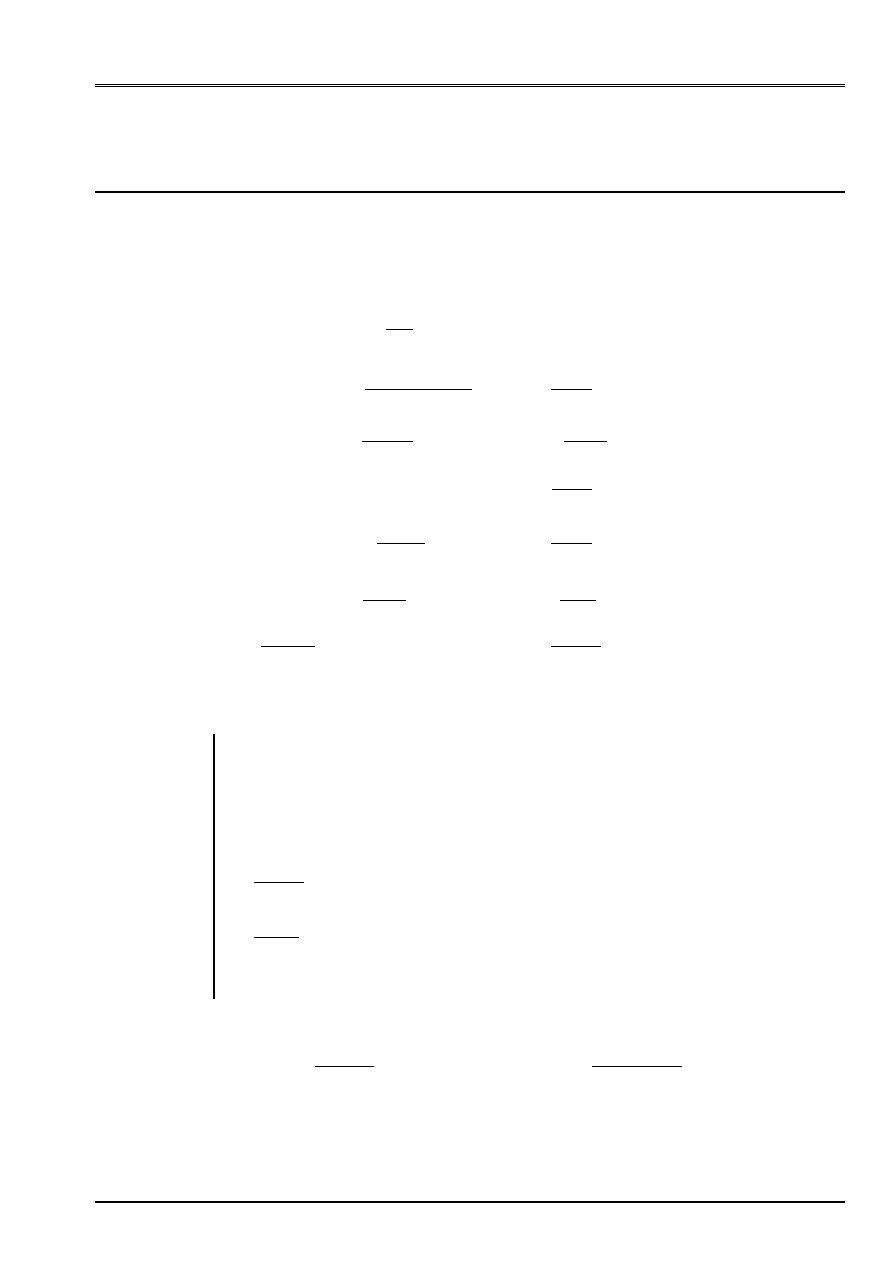
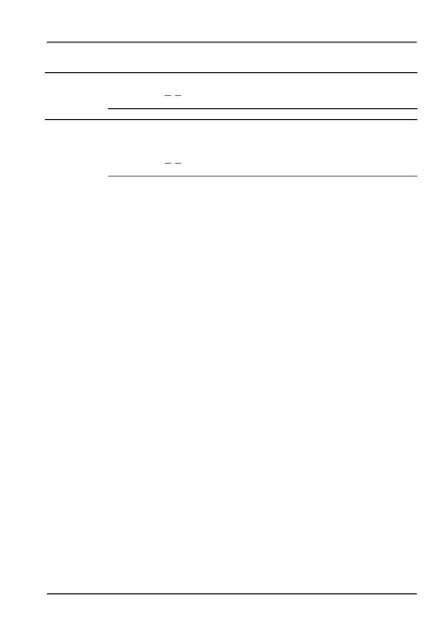
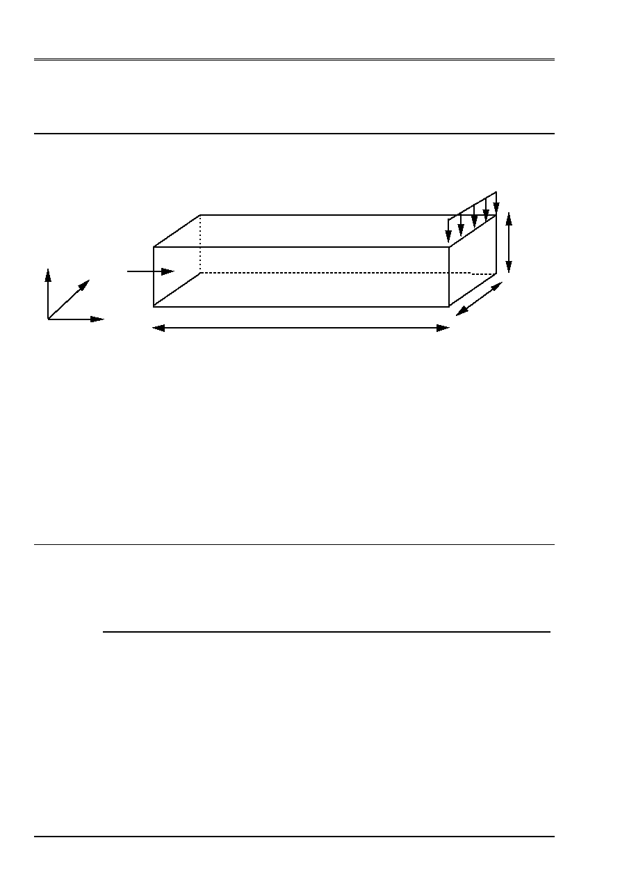
11.1 Characteristics of modeling
The beam is with a grid in solid elements quadratic HEXA20.
L = 2
surf1
B = 0.1
= 0.2 have
fz
L
2
X
y
Z
The beam is embedded on the level of the section surf1. It is subjected to a unit sharp effort
who is modelized by a linear density of load fz applying to 4 constituent meshs SEG3
the higher edge L2.
11.2 Characteristics of the mesh
The beam is with a grid with 640 solid elements quadratic HEXA20.
The model comprises 3665 nodes.
11.3 Functionalities
tested
The functionality is tested
FORCE_ARETE
of
AFFE_CHAR_MECA
.
12 Results of modeling E
12.1 Values
tested
One tests the value of the arrow according to Z of the node medium of the section where the loading is applied
(N62 node).
Identification Reference Aster %
difference
dz of the N62 node
8 10
7
7.9523
10
7
0.596
12.2 Remarks
The value of reference corresponds to the value given by R.D.M.
Code_Aster
®
Version
6.2
Titrate:
SSLL102 - Fixed beam subjected to unit efforts
Date:
20/12/02
Author (S)
:
J.M. PROIX, J. PELLET, F. LEBOUVIER
Key:
V3.01.102-D
Page:
13/18
Manual of Validation
V3.01 booklet: Linear statics of the linear structures
HT-66/02/001/A
13 Modeling
F
13.1 Characteristics of modeling
The model is composed of 10 elements right beam of Euler. The section is circular full, of radius
0.1m.
13.2 Characteristics of the mesh
It consists of 10 elements POU_D_E. The length of the beam is L = 6 m
13.3 Functionalities tested
Controls
AFFE_CARA_ELEM
BEAM: SECTION
“GENERAL”
AFFE_CHAR_MECA DDL_IMPO
CALC_ELEM EFGE_ELNO_DEPL
SIGM_ELNO_DEPL
14 Results of modeling F
14.1 Values
tested
14.1.1 Interior efforts
Results
analytical
Results
Aster Variation
(%)
Vy (0) 6.0000E+03 6.0000E+03
0.0000
Vy (6) 1.2000E+04 1.2000E+04
0.0000
MFZ
()
2 3
1.3856E+04 1.3856E+04
0.0000
14.1.2 Stress
Results
analytical
Results
Aster Variation
(%)
SIXX
()
2 3
1.7642E+07 1.7642E+07
0.0000
Code_Aster
®
Version
6.2
Titrate:
SSLL102 - Fixed beam subjected to unit efforts
Date:
20/12/02
Author (S)
:
J.M. PROIX, J. PELLET, F. LEBOUVIER
Key:
V3.01.102-D
Page:
14/18
Manual of Validation
V3.01 booklet: Linear statics of the linear structures
HT-66/02/001/A
15 Modeling
G
15.1 Characteristics of modeling
The model is composed of 10 elements right beam of Timoshenko with roll. The section
is circular full, of radius 0.1m.
15.2 Characteristics of the mesh
It consists of 10 elements POU_D_TG. The length of the beam is L = 6 m
15.3 Functionalities tested
Controls
AFFE_CARA_ELEM
BEAM: SECTION
“GENERAL”
AFFE_CHAR_MECA DDL_IMPO
CALC_ELEM EFGE_ELNO_DEPL
SIGM_ELNO_DEPL
16 Results of modeling G
16.1 Values
tested
16.1.1 Interior efforts
Results
analytical
Results
Aster Variation
(%)
Vy (0) 6.0000E+03 6.0000E+03
0.0000
Vy (6) 1.2000E+04 1.2000E+04
0.0000
MFZ
()
2 3
1.3856E+04 1.3856E+04
0.0000
16.1.2 Stress
Results
analytical
Results
Aster Variation
(%)
SIXX
()
2 3
1.7642E+07 1.7642E+07
0.0000
Code_Aster
®
Version
6.2
Titrate:
SSLL102 - Fixed beam subjected to unit efforts
Date:
20/12/02
Author (S)
:
J.M. PROIX, J. PELLET, F. LEBOUVIER
Key:
V3.01.102-D
Page:
15/18
Manual of Validation
V3.01 booklet: Linear statics of the linear structures
HT-66/02/001/A
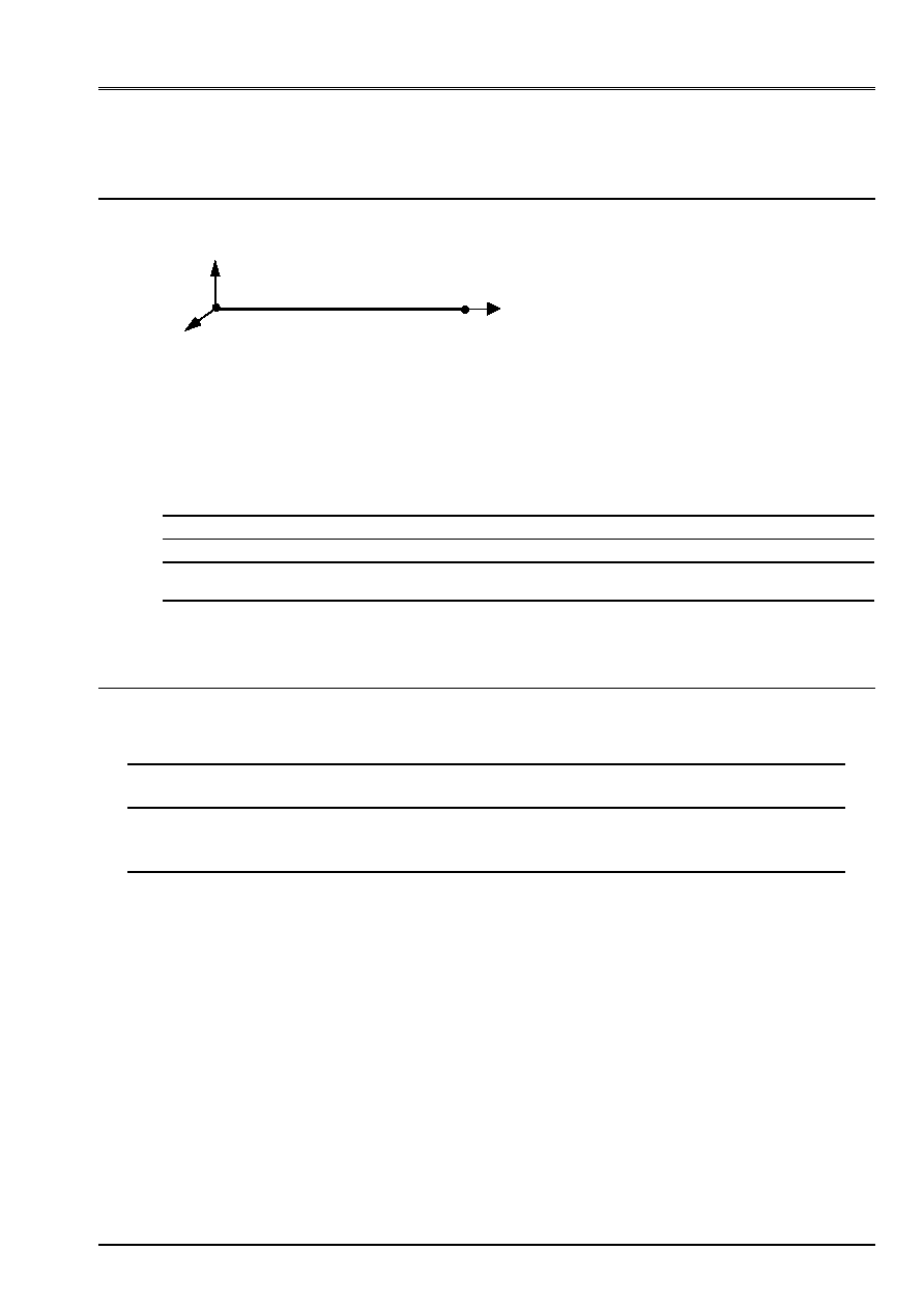
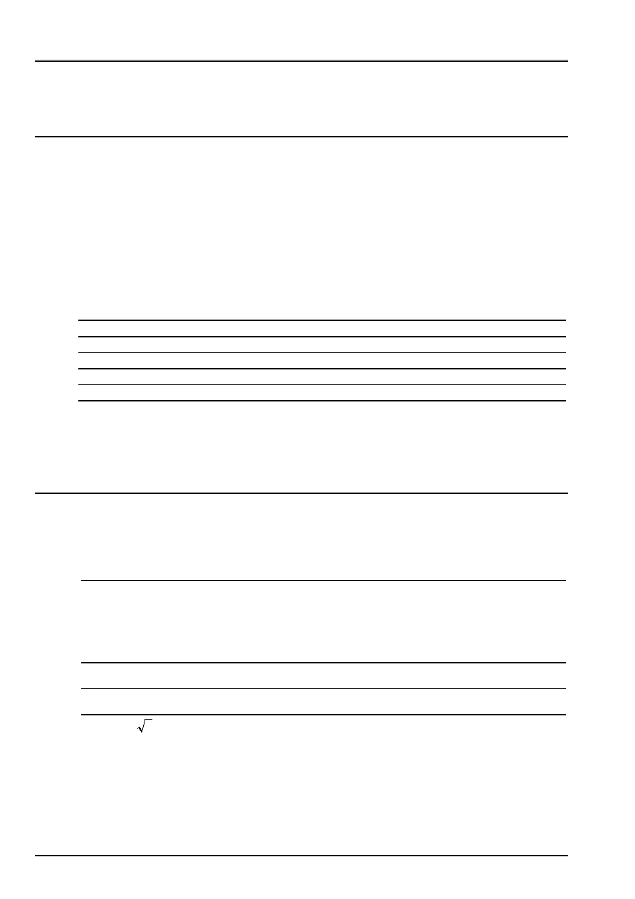
17 Modeling
H
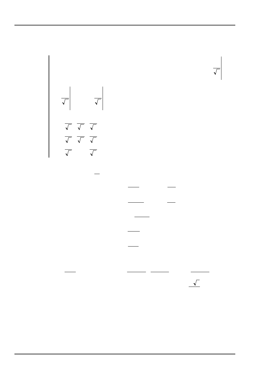
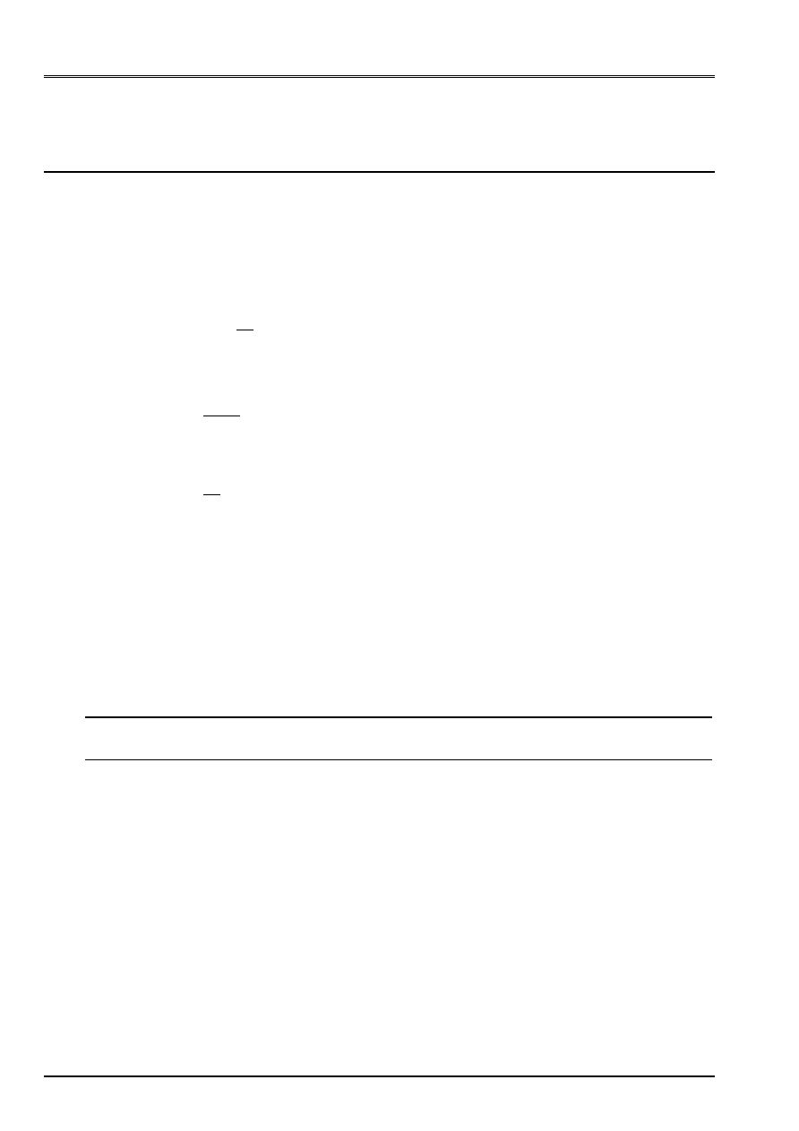
17.1 Characteristics of modeling
B
4
y
X
Z O
Modeling COQUE_C_PLAN
- Rectangular Section
- Limiting Conditions: Not O U = v =
Z
= 0
- Unit Loading: Not B F
X
, F
y
and M
Z
17.2 Characteristics of the mesh
A number of nodes: 9
A number of meshs and types: 4
SEG3
17.3 Functionalities tested
Controls
AFFE_MODELE AFFE
“COQUE_C_PLAN”
AFFE_CARA_ELEM HULL
THICK
CALC_ELEM OPTION
“EFGE_ELNO_DEPL”
“SIGM_ELNO_DEPL”
AFFE_CHAR_MECA
FORCE_NODALE
FX FY MZ
18 Results of modeling H
18.1 Values
tested
Loading case
Beam Identification
Reference
Aster %
difference
F
X
= 1
S1
U
X
(B)
5. 10
10
5.
10
10
0.
xx
(0)
5.
5.
0.
F
y
= 1
S1
U
y
(B)
2. 10
7
2.007
10
7
0.333
Z
(B)
1.5 10
7
1.5
10
7
0.
xx
(0)
300. 289.27
3.576
M
Z
= 1
S1
U
y
(B)
1.5 10
7
1.5
10
7
0.
Z
(B)
1.5 10
7
1.5 10
7
0.
xx
(0)
150. 150.
0.
18.2 Remarks
The width for modeling COQUE_C_PLAN is imposed on 1 in Code_Aster. In
consequence, we multiplied by 0.1 the Young modulus to take account of the real width of
the beam. This width of 1 modifies the inertia of the beam and consequently the value of the stress
xx
who is 10 with times lower than the value of reference. Moreover, for displacements, the results
differ from modeling A because of the change of reference mark.
Code_Aster
®
Version
6.2
Titrate:
SSLL102 - Fixed beam subjected to unit efforts
Date:
20/12/02
Author (S)
:
J.M. PROIX, J. PELLET, F. LEBOUVIER
Key:
V3.01.102-D
Page:
16/18
Manual of Validation
V3.01 booklet: Linear statics of the linear structures
HT-66/02/001/A
19 Modeling
I
19.1 Characteristics of modeling
The model is composed of 21 elements TUYAU_3M.
19.2 Characteristics of the mesh
It consists of 21 meshs SEG3. The length of the beam is L = 6 m
19.3 Functionalities tested
Controls
AFFE_CARA_ELEM
BEAM: SECTION
“GENERAL”
AFFE_CHAR_MECA DDL_IMPO
AFFE_CHAR_MECA_F FORCE_POUTRE
MECA_STATIQUE
STAT_NON_LINE COMP_INCR
RELATION
ELAS
CALC_ELEM
OPTION
SIEF_ELNO_ELGA
CALC_NO
OPTION
FORC_NODA
CALC_NO
OPTION
REAC_NODA
CALC_NO
OPTION
EFGE_NOEU_DEPL
20 Results of modeling I
20.1 Values
tested
20.1.1 Displacements
Results
analytical
Results
Aster Variation
(%)
Maximum Dy
9.38888E-03
9.44033E-03
0.55
20.1.2 Interior efforts
Results
analytical
Results
Aster Variation
(%)
Vy (x=0) 6.0000E+03
6.0076E+03
0.127
Vy (x=L=6) 1.2000E+04 1.1995E+04
0.042
MFZ
()
2 3
1.3856E+04 1.388E+04
0.171

Code_Aster
®
Version
6.2
Titrate:
SSLL102 - Fixed beam subjected to unit efforts
Date:
20/12/02
Author (S)
:
J.M. PROIX, J. PELLET, F. LEBOUVIER
Key:
V3.01.102-D
Page:
17/18
Manual of Validation
V3.01 booklet: Linear statics of the linear structures
HT-66/02/001/A
21 Summary of the results
This test makes it possible simultaneously to check the correct operation of the elements
POU_D_E
,
POU_D_T
and
POU_D_TG
on 3 types of different sections. The perfect coincidence of the results with the solutions
analytical (RDM) is normal, and must always be observed, since the solution is contained in
functions of form of the elements.
Moreover, modeling E makes it possible to test the loading distributed on edges of elements
voluminal. The variation with the analytical solution (RDM) is lower than 0.6%.
Modelings F, G and I make it possible to test the loading distributed (linear variation) for
elements of beam POU_D_E, POU_D_TG and pipe sections. The variation with the analytical solution
(RDM) is lower than 0.6%.
For modeling COQUE_C_PLAN the results are satisfactory (displacements and stresses)
for the unit loadings of extension type and bending (imposed moment). For the loading of
bending (load imposed at an end) the error on displacement is weak 0.5%. It is more
important on the stress: 3.6%.

Code_Aster
®
Version
6.2
Titrate:
SSLL102 - Fixed beam subjected to unit efforts
Date:
20/12/02
Author (S)
:
J.M. PROIX, J. PELLET, F. LEBOUVIER
Key:
V3.01.102-D
Page:
18/18
Manual of Validation
V3.01 booklet: Linear statics of the linear structures
HT-66/02/001/A
Intentionally white left page.