
Code_Aster
®
Version
7.2
Titrate:
SSLL106 - Right pipe
Date:
05/01/04
Author (S)
:
J. Mr. PROIX
Key:
V3.01.106-B
Page:
1/22
Manual of Validation
V3.01 booklet: Linear statics of the linear structures
HT-66/03/008/A
Organization (S)
: EDF-R & D/AMA
Manual of Validation
V3.01 booklet: Linear statics of the linear structures
Document: V3.01.106
SSLL106 - Right pipe
Summary:
This test allows a simple checking of the right pipe sections in static mechanics of the structures
linear.
The model is linear.
For each modeling, 6 types of loading are applied at the end: a traction, 2 efforts
edges, 2 moments bending and a torsion. One applies moreover one internal pressure, a linear force
distributed and a thermal expansion.
The values tested are displacements, the efforts with the nodes, and the stresses and deformations at the points
of Gauss. The reference solution is analytical (RDM).
Two modelings (A and B) make it possible to test the element PIPE with 3 modes of Fourier (modeling
TUYAU_3M)
: modeling A uses
MECA_STATIQUE
, modeling B uses
STAT_NON_LINE
(elastic behavior).
Two modelings (C and D) make it possible to test the element PIPE with 6 modes of Fourier (modeling
TUYAU_6M).
Two modelings (E and F) make it possible to test the element PIPE with 3 modes of Fourier and 4 nodes
(modeling TUYAU_3M).
Code_Aster
®
Version
7.2
Titrate:
SSLL106 - Right pipe
Date:
05/01/04
Author (S)
:
J. Mr. PROIX
Key:
V3.01.106-B
Page:
2/22
Manual of Validation
V3.01 booklet: Linear statics of the linear structures
HT-66/03/008/A
1
Problem of reference
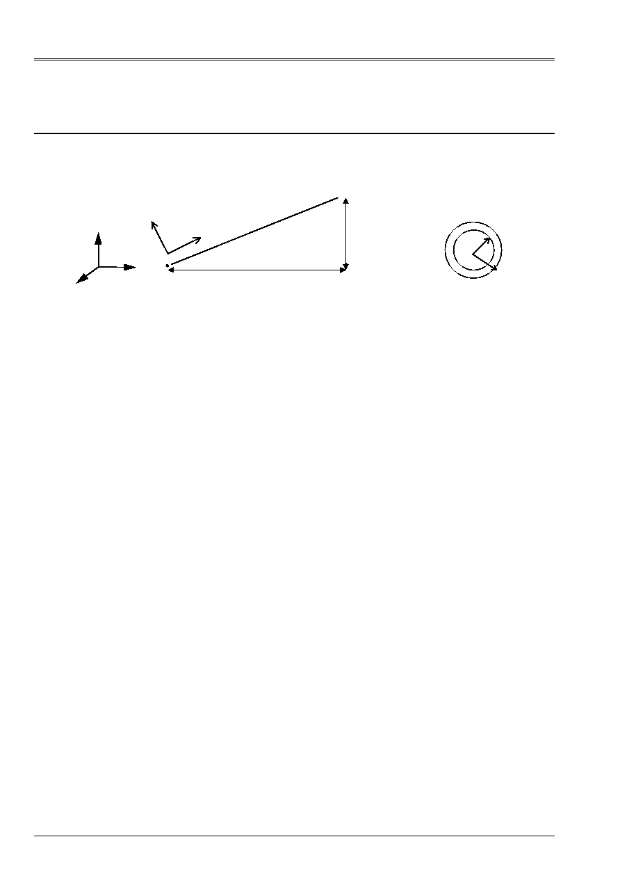
1.1 Geometry
Right beam length
L
, of directing vector (4, 3, 0).
O
B
L
L =5
Y
X
Z O
4
3
X
y
Z
0.032
0.04
Section of the pipe
Tubular section of external radius has = 0.04m, of radius interns B = 0.032m, thickness E = 0.008 m
1.2
Material properties
E = 2. 10
11
AP
= 0.3
density
=7800 kg/m3, thermal expansion factor
5
10
-
=
1.3
Boundary conditions and loadings
·
Embedding out of O
·
6 elementary Loadings at the end B
-
in reference mark (X, y, Z) related to the beam:
F
X
= 5.10
2
NR M
X
= 5.10
2
Nm
F
y
= 5.10
2
NR M
y
= 5.10
2
Nm
F
Z
= 5.10
2
NR M
Z
= 5.10
2
Nm
-
maybe, in the total reference mark (X, Y, Z):
-
1 loading of traction: F
X
= 4.10
2
NR and
F
Y
= 3.10
2
NR
-
2 sharp efforts:in the plan (oxy) F
X
= 3.10
2
NR and
F
Y
= 4.10
2
NR and in the plan
(oyz) F
Z
= 5.10
2
NR
-
1 torque: M
X
= 4.10
2
Nm and
M
Y
= 3.10
2
Nm
-
2 sharp efforts:in the plan (oxy) M
X
= 3.10
2
Nm and
M
Y
= 4.10
2
Nm and in the plan
(oyz) M
Z
= 5.10
2
Nm
·
Internal pressure: P=10
7
AP
·
Gravity, with g=10m/s ², in the direction - Z
·
Linear loading, Fz=-141.146 NR/m (what corresponds to the load due to gravity:
Fz=mg)
·
Thermal dilation: Temp = 100°C
1.4
Notation of the characteristics of cross sections
The geometrical characteristics of the cross sections are noted:
S:
surface of the section
I I
y
Z
,
:
geometrical moments of inertia compared to the main axes of inertia of
section
Jx:
constant of torsion
Code_Aster
®
Version
7.2
Titrate:
SSLL106 - Right pipe
Date:
05/01/04
Author (S)
:
J. Mr. PROIX
Key:
V3.01.106-B
Page:
3/22
Manual of Validation
V3.01 booklet: Linear statics of the linear structures
HT-66/03/008/A
2
Reference solution
2.1
Method of calculation used for the reference solution
·
Analytical solution [bib1]: displacements out of B in the reference mark (Oxyz) related to the beam.
()
(
) (
)
Simple traction
Pure bending
Pure bending
Torsion
Pure bending
Pure bending
Pressure
U
F
L
E S
U
F L
E I
L F
E I
L F
E I
MR. L
G J
U
MR. L
E I
MR. L
E I
X
X
y
y
Z
Z
y
Z
y
Z
y
X
X
X
Z
y
y
y
y
y
uz
Fz L
E I y
U y
M Z L
E I Z
Z
M Z L
E I Z
ur
P
E
has
B
has
R
B
R
=
=
=
= -
=
= -
=
=
=
= +
=
-
-
+ +
3
2
2
2
3
2
2
2
3
3
2
2
2
2
2
1
1
2
2
calculated in
in fact
vary between
in
and
in
R
B has
U
R B
R
has
R
= +
=
=
-
-
2
7 12 10
7 78 10
6
6
,
,
Here, the values are obtained with:
S
m
Iy
Iz
m
J
m
L
m
X
=
=
=
=
=
-
-
-
1809557 10
118707 10
2 37414 10
5
3
2
6
4
6
4
.
.
.
For the generalized deformations of beam, one obtains, by the law of behavior:
(
)
(
)
Z
I
E
Z
M
Z
S
G
Z
F
xz
y
y
y
X
X
X
y
Z
y
Z
y
Z
y
xy
X
X
I
E
M
J
G
M
I
E
X
L
F
I
E
X
L
F
S
G
F
S
E
F
E
+
=
=
=
=
-
=
-
=
=
=
pure
Bending
pure
Bending
Torsion
simple
Bending
simple
Bending
simple
Traction
Code_Aster
®
Version
7.2
Titrate:
SSLL106 - Right pipe
Date:
05/01/04
Author (S)
:
J. Mr. PROIX
Key:
V3.01.106-B
Page:
4/22
Manual of Validation
V3.01 booklet: Linear statics of the linear structures
HT-66/03/008/A
Loading of gravity and linear loading:
If
p
indicate the distributed load, the moment in the beginning is worth:
2
)
(
2
pL
O
M
=
and of following displacement
Z at the end B is worth:
I.E.(internal excitation)
pL
B
U
Z
8
)
(
4
=
The thermal loading of dilation led to an axial displacement (in the local direction X):
()
T
L
B
U
X
=
)
(
The deformations of free dilation of the surface of the pipe are simply, in local reference mark:
()
T
yy
xx
=
=
Finally to validate the calculation of the matrix of mass, a modal analysis of the first 12 modes
clean (with embedding out of O) must give, for the modes of bending:
S
I.E.(internal excitation)
L
F
I
I
2
=
Lambdai mode
Frequency
1 1,87510407
2,9030234
2 4,69409113 18,192937
3 7,85475744 50,9407506
4 10,9955407
99,8235399
5 14,1371684
165,015464
6 17,2787596
246,504532
7 20,4203522
344,291453
8 23,5619449
458,376195
9 26,7035376
588,758758
10 29,8451302
735,43914
11 32,9867229
898,417343
12 36,1283155
1077,69337
2.2
Results of reference
·
Displacement at the point B, efforts, stresses and deformations in the vicinity of the point O.
·
Deformation generalized.
·
Eigen frequencies
2.3
Uncertainty on the solution
Analytical solution.
2.4 References
bibliographical
[1]
Manual of validation, test SSLL102 fixed Beam subjected to unit efforts
[V3.01.102]

Code_Aster
®
Version
7.2
Titrate:
SSLL106 - Right pipe
Date:
05/01/04
Author (S)
:
J. Mr. PROIX
Key:
V3.01.106-B
Page:
5/22
Manual of Validation
V3.01 booklet: Linear statics of the linear structures
HT-66/03/008/A
3 Modeling
With
3.1
Characteristics of modeling
10 elements
PIPE.
3.2
Characteristics of the mesh
10 meshs
SEG3
. The beam is directed according to the vector (4, 3, 0).
3.3 Functionalities
tested
Controls
AFFE_MODELE MODELING
PIPE
AFFE_CARA_ELEM BEAM
SECTION RINGS
MACRO_ELAS_MULT
OPTION
SIEF_ELGA_DEPL
OPTION
EPSI_ELGA_DEPL
OPTION
EFGE_ELNO_DEPL
Notice on the contents of the fields:
Fields at the points of Gauss for the element PIPE
,
EPSI_ELGA_DEPL
and
SIEF_ELGA_DEPL,
who provide the strains and the stresses to the points of integration
in the local reference mark of the element, are organized in the following way:
The values are stored:
·
for each point of Gauss in the length, (n=1, 3)
·
for each point of integration in the thickness, (n=1, 2N
NECK
+1=7)
·
for each point of integration on the circumference, (n=1, 2N
SECT
+1=33)
·
6 components of strain or stresses:
EPXX EPYY EPZZ EPXY EPXZ EPYZ
or
SIXX SIYY SIZZ SIXY
SIXZ SIYZ
where X indicates the direction given by the two nodes nodes of
the element, Y represents the angle
describing the circumference and Z
represent the radius.
EPZZ
and
EPYZ
agent with
rr
R
,
in
case of the deformations and
SIZZ
and
SIYZ
agent with
rr
R
,
in
the case of the stresses is taken equal to zero.
(for
MECA_STATIQUE
or
MACRO_ELAS_MULT
, the number of layers is fixed, and equal to 3, and
the number of sectors is equal to 16).
EFGE_ELNO_DEPL
represent the efforts generalized with the 3 nodes in the conventional way:
NR,
VY, VZ, MT, MFY, MFZ
.
Code_Aster
®
Version
7.2
Titrate:
SSLL106 - Right pipe
Date:
05/01/04
Author (S)
:
J. Mr. PROIX
Key:
V3.01.106-B
Page:
6/22
Manual of Validation
V3.01 booklet: Linear statics of the linear structures
HT-66/03/008/A
4
Results of modeling A
4.1 Values
tested
Loading case
Size
Reference
Aster %
difference
F
X
= 4.10
2
DX
5.53E06
5.52E06
0.04
F
Y
= 3.10
2
DY
4.14E06
4.14E06
0.04
F
X
= 3.10
2
DRZ
2.63E02
2.63E02
0.04
F
Y
= 4.10
2
DX
5.27E02
5.26E02
0.056
DY
7.02E02
7.02E02
0.056
F
Z
= 5.10
2
DRX
1.58E02
1.58E02
0.04
DRY
2.11E02
2.11E02
0.039
DZ
8.78E02
8.77E02
0.056
M
X
= 4.10
2
DRX
1.10E02
1.10E02
0
M
Y
= 3.10
2
DRY
8.21E03
8.21E03
0
M
X
= 3.10
2
DRX
6.32E03
6.32E03
0.04
M
Y
= 4.10
2
DRY
8.42E03
8.42E03
0.04
DZ
2.63E02
2.63E02
0.04
M
Z
= 5 10
2
DRZ
1.05E02
1.05E02
0.039
DX
1.58E02
1.58E02
0.04
DY
2.11E02
2.11E02
0.039
7: pressure
WO
7.38E06
7.16E06
2.946
8: gravity
DZ
4.646
E-02 4.642
E-02
0.09
9: charge distributed
DZ
4.646
E-02 4.642
E-02
0.09
Loading case
Field
Net Point Component Reference
Aster %
difference
1
EFGE_ELNO_DEPL
M18 1 NR
5.00E+02
5.01E+02 0.136
1
EPSI_ELGA_DEPL
M18 1 EPXX 1.38E06
1.38E06
0.031
1
SIEF_ELGA_DEPL
M18 1 SIXX 2.76E+05
2.73E+05
1.159
4
EFGE_ELNO_DEPL
M18 1 MT
5.00E+02
5.00E+02 0
4
EPSI_ELGA_DEPL
M18 1 EPXY 8.77E05 8.76E05
0.102
4
EPSI_ELGA_DEPL
M18 693 EPXY 1.09E04 1.10E04 0.049
4
SIEF_ELGA_DEPL
M18 1 SIXY 6.75E+06 6.74E+06
0.159
4
SIEF_ELGA_DEPL
M18 693 SIXY
8.42E+06 8.42E+06 0.049
5
EFGE_ELNO_DEPL
M18 1 MFY 5.00E+02
5.01E+02 0.123
5
EPSI_ELGA_DEPL
M18 479 EPXX
6.74E05
6.74E05 0.046
5
SIEF_ELGA_DEPL
M18 479 SIXX
1.35E+07
1.33E+07 1.288
6
EFGE_ELNO_DEPL
M18 1 MFZ 5.00E+02
5.01E+02 0.123
6
EPSI_ELGA_DEPL
M18 471 EPXX
6.74E05
6.74E05 0.046
6
SIEF_ELGA_DEPL
M18 471 SIXX
1.35E+07
1.33E+07 1.288
7
EPSI_ELGA_DEPL
M18 1 EPYY 2.28E04
2.24E04
1.716
7
EPSI_ELGA_DEPL
M18 693 EPYY
1.78E04
1.79E04 0.741
7
SIEF_ELGA_DEPL
M18 1 SIYY 4.56E+07
4.53E+07
0.641
7
SIEF_ELGA_DEPL
M18 693 SIYY
3.56E+07
3.54E+07 0.371
8
EFGE_ELNO_DEPL
M1 1 MFY
1764.3
1728
2
9
EFGE_ELNO_DEPL
M1 1 MFY
1764.3
1728
2
Code_Aster
®
Version
7.2
Titrate:
SSLL106 - Right pipe
Date:
05/01/04
Author (S)
:
J. Mr. PROIX
Key:
V3.01.106-B
Page:
7/22
Manual of Validation
V3.01 booklet: Linear statics of the linear structures
HT-66/03/008/A
Generalized deformations
DEGE_ELNO_DEPL
:
Loading case
Loadings
Size
Reference
Aster %
difference
1 F
X
= 4.10
2
EPXX
1.38155E-06
1.38155E-06
0.04
F
Y
= 3.10
2
2 F
X
= 3.10
2
GAXY 3.5920E-06 4.7415E06 32
F
Y
= 4.10
2
KZ
1.0530E02 1.04E02 1.2
3 F
Z
= 5.10
2
GAXZ 3.5920E-06 4.7415E06
32
KY
1.0530E02
1.04E02
1.2
4 M
X
= 4.10
2
GAT 2.73783E-03 2.73783E-03 0
M
Y
= 3.10
2
5 M
X
= 3.10
2
KY
2.1060E-03 2.1052E-03 0.04
M
Y
= 4.10
2
6 M
Z
= 5 10
2
KZ
2.1060E-03 2.1052E-03
0.04
Fréquenc
E clean
Reference
Aster %
difference
1 2.90229
2.90378
0.05
2 2.90229
2.
90378
0.05
3 18.18967
18.2047
0.08
4 18.18967
18.2047
0.08
5 50.99367
51.006 0.02
6 50.99367
51.006 0.02
7 99.81783
100.0478
0.2
8 99.81783
100.0478
0.2
9 157.0190
157.0185 0.001
10 164.9922
165.606 0.3
11 164.9922
165.606 0.3
12 253.185 247.82 2
4.2 Remarks
The values of shearings corresponding to the shearing action are not precise for this
modeling. This is due to the functions of interpolation of command 2 of this element, for displacements
of beam and rotations of beams. As transverse shearings of beam are obtained
by:
dx
y
Z
xy
-
=
, and that for the pure bending, rotations vary like polynomials of command 2,
but displacements, like polynomials of command 3, which is badly approached by the functions
of interpolation. The derivative of displacements is thus not precise.

Code_Aster
®
Version
7.2
Titrate:
SSLL106 - Right pipe
Date:
05/01/04
Author (S)
:
J. Mr. PROIX
Key:
V3.01.106-B
Page:
8/22
Manual of Validation
V3.01 booklet: Linear statics of the linear structures
HT-66/03/008/A
5 Modeling
B
5.1
Characteristics of modeling
10 elements
PIPE
, calculation with
STAT_NON_LINE
.
5.2
Characteristics of the mesh
10 meshs
SEG3
. The beam is directed according to the vector (4, 3, 0).
5.3 Functionalities
tested
Controls
AFFE_MODELE
MODELING
PIPE
AFFE_CARA_ELEM BEAM
SECTION RINGS
STAT_NON_LINE COMP_INCR
RELATION ELAS
COMP_INCR
TUYAU_NCOU
3
COMP_INCR
TUYAU_NSEC
16
OPTION
SIEF_ELNO_ELGA
Notice on the contents of the fields:
Stress fields at the points of Gauss for the element PIPE,
SIEF_ELGA,
in
the local reference mark of the element, are organized in the following way:
The values are stored:
·
for each point of Gauss in the length, (n=1, 3)
·
for each point of integration in the thickness, (n=1, 2N
NECK
+1)
·
for each point of integration on the circumference, (n=1, 2N
SECT
+1)
·
6 components of strain or stresses:
EPXX EPYY EPZZ EPXY EPXZ EPYZ
or
SIXX SIYY SIZZ SIXY
SIXZ SIYZ
where X indicates the direction given by the two nodes nodes of
the element, Y represents the angle
describing the circumference and Z
represent the radius.
EPZZ
and
EPYZ
agent with
rr
R
,
in
case of the deformations and
SIZZ
and
SIYZ
agent with
rr
R
,
in
the case of the stresses is taken equal to zero.
(in
STAT_NON_LINE
, the number of layers is variable, as well as the number of sectors.
One uses here 3 layers and 16 sectors by analogy with modeling A).
Code_Aster
®
Version
7.2
Titrate:
SSLL106 - Right pipe
Date:
05/01/04
Author (S)
:
J. Mr. PROIX
Key:
V3.01.106-B
Page:
9/22
Manual of Validation
V3.01 booklet: Linear statics of the linear structures
HT-66/03/008/A
6
Results of modeling B
6.1 Values
tested
Loading case
Size
Reference
Aster %
difference
1 DX
5.53E06
5.52E06
0.04
1 DY
4.14E06
4.14E06
0.04
2 DRZ
2.63E02
2.63E02
0.04
2 DX
5.27E02
5.26E02
0.056
2 DY
7.02E02
7.02E02
0.056
3 DRX
1.58E02
1.58E02
0.04
3 DRY
2.11E02
2.11E02
0.039
3 DZ
8.78E02
8.77E02
0.056
4 DRX
1.10E02
1.10E02
0
4 DRY
8.21E03
8.21E03
0
5 DRX
6.32E03
6.32E03
0.04
5 DRY
8.42E03
8.42E03
0.04
5 DZ
2.63E02
2.63E02
0.04
6 DRZ
1.05E02
1.05E02
0.039
6 DX
1.58E02
1.58E02
0.04
6 DY
2.11E02
2.11E02
0.039
7 WO
7.38E06
7.16E06
2.946
Loading case
Field
Net
Not Component Reference
Aster %
difference
1
SIEF_ELGA
M18 Z SIXX 2.76E+05
2.73E+05
1.159
1
SIEF_ELNO_ELGA
M18 1 NR 5.00E+02
5.01E+02 0.136
4
SIEF_ELGA
M18 1 SIXY 6.75E+06
6.74E+06
0.159
4
SIEF_ELGA
M18 693
SIXY 8.42E+06
8.42E+06 0.049
4
SIEF_ELNO_ELGA
M18 1 MT 5.00E+02
5.00E+02 0
5
SIEF_ELGA
M18 479
SIXX 1.35E+07
1.33E+07 1.288
5
SIEF_ELNO_ELGA
M18 1 MFY 5.00E+02
5.01E+02 0.123
6
SIEF_ELGA
M18 471
SIXX 1.35E+07
1.33E+07 1.288
6
SIEF_ELNO_ELGA
M18 1 MFZ 5.00E+02
5.01E+02 0.123
7
SIEF_ELGA
M18 1 SIYY 4.56E+07
4.53E+07
0.641
7
SIEF_ELGA
M18 693
SIYY 3.56E+07
3.54E+07 0.371
Generalized deformations
DEGE_ELNO_DEPL
:
Loading case
Loadings
Size
Reference
Aster %
difference
1 F
X
= 4.10
2
EPXX
1.38155E-06 1.38155E-06
0.04
F
Y
= 3.10
2
2 F
X
= 3.10
2
GAXY 3.5920E-06
4.7415E06
32
F
Y
= 4.10
2
KZ 1.0530E02
1.04E02
1.2
3 F
Z
= 5.10
2
GAXZ
3.5920E-06
4.7415E06
32
KY
1.0530E02
1.04E02
1.2
4 M
X
= 4.10
2
GAT 2.73783E-03
2.73783E-03
0
M
Y
= 3.10
2
5 M
X
= 3.10
2
KY
2.1060E-03
2.1052E-03
0.04
M
Y
= 4.10
2
6 M
Z
= 5 10
2
KZ 2.1060E-03
2.1052E-03
0.04

Code_Aster
®
Version
7.2
Titrate:
SSLL106 - Right pipe
Date:
05/01/04
Author (S)
:
J. Mr. PROIX
Key:
V3.01.106-B
Page:
10/22
Manual of Validation
V3.01 booklet: Linear statics of the linear structures
HT-66/03/008/A
6.2 Remarks
The values of shearings corresponding to the shearing action are not precise for this
modeling. This is due to the functions of interpolation of command 2 of this element, for displacements
of beam and rotations of beams. As transverse shearings of beam are obtained
by:
dx
y
Z
xy
-
=
, and that for the pure bending, rotations vary like polynomials of command 2,
but displacements, like polynomials of command 3, which is badly approached by the functions
of interpolation. The derivative of displacements is thus not precise.

Code_Aster
®
Version
7.2
Titrate:
SSLL106 - Right pipe
Date:
05/01/04
Author (S)
:
J. Mr. PROIX
Key:
V3.01.106-B
Page:
11/22
Manual of Validation
V3.01 booklet: Linear statics of the linear structures
HT-66/03/008/A
7 Modeling
C
7.1
Characteristics of modeling
10 elements
TUYAU_6M
.
7.2
Characteristics of the mesh
10 meshs
SEG3
. The beam is directed according to the vector (4, 3, 0).
7.3 Functionalities
tested
Controls
AFFE_MODELE MODELING
TUYAU_6M
AFFE_CARA_ELEM BEAM
SECTION RINGS
MACRO_ELAS_MULT
OPTION
SIEF_ELGA_DEPL
OPTION
EPSI_ELGA_DEPL
OPTION
EFGE_ELNO_DEPL
Notice on the contents of the fields:
Fields at the points of Gauss for the element PIPE
,
EPSI_ELGA_DEPL
and
SIEF_ELGA_DEPL,
who provide the strains and the stresses to the points of integration
in the local reference mark of the element, are organized in the following way:
The values are stored:
·
for each point of Gauss in the length, (n=1, 3)
·
for each point of integration in the thickness, (n=1, 2N
NECK
+1=7)
·
for each point of integration on the circumference, (n=1, 2N
SECT
+1=33)
·
6 components of strain or stresses:
EPXX EPYY EPZZ EPXY EPXZ EPYZ
or
SIXX SIYY SIZZ SIXY
SIXZ SIYZ
where X indicates the direction given by the two nodes nodes of
the element, Y represents the angle
describing the circumference and Z
represent the radius.
EPZZ
and
EPYZ
agent with
rr
R
,
in
case of the deformations and
SIZZ
and
SIYZ
agent with
rr
R
,
in
the case of the stresses is taken equal to zero.
(for
MECA_STATIQUE
or
MACRO_ELAS_MULT
, the number of layers is fixed, and equal to 3, and
the number of sectors is equal to 16).
EFGE_ELNO_DEPL
represent the efforts generalize with the 3 nodes in the conventional way:
NR,
VY, VZ, MT, MFY, MFZ
.
Code_Aster
®
Version
7.2
Titrate:
SSLL106 - Right pipe
Date:
05/01/04
Author (S)
:
J. Mr. PROIX
Key:
V3.01.106-B
Page:
12/22
Manual of Validation
V3.01 booklet: Linear statics of the linear structures
HT-66/03/008/A
8
Results of modeling C
8.1 Values
tested
Loading case
Size
Reference
Aster %
difference
1 F
X
= 4.10
2
DX
5.53E06
5.52E06
0.04
1 F
Y
= 3.10
2
DY
4.14E06
4.14E06
0.04
2 F
X
= 3.10
2
DRZ
2.63E02
2.63E02
0.04
2 F
Y
= 4.10
2
DX
5.27E02
5.26E02
0.056
2
DY
7.02E02
7.02E02
0.056
3 F
Z
= 5.10
2
DRX
1.58E02
1.58E02
0.04
3
DRY
2.11E02
2.11E02
0.039
3
DZ
8.78E02
8.77E02
0.056
4 M
X
= 4.10
2
DRX
1.10E02
1.10E02
0
4 M
Y
= 3.10
2
DRY
8.21E03
8.21E03
0
5 M
X
= 3.10
2
DRX
6.32E03
6.32E03
0.04
5 M
Y
= 4.10
2
DRY
8.42E03
8.42E03
0.04
5
DZ
2.63E02
2.63E02
0.04
6 M
Z
= 5 10
2
DRZ
1.05E02
1.05E02
0.039
6
DX
1.58E02
1.58E02
0.04
6
DY
2.11E02
2.11E02
0.039
7: pressure
WO
7.38E06
7.16E06
2.946
8: gravity
DZ
4.646
E-02 4.642
E-02
0.09
9: charge distributed
DZ
4.646
E-02 4.642
E-02
0.09
Loading case
Field
Net Point Component Reference
Aster %
difference
1
EFGE_ELNO_DEPL
M18 1 NR
5.00E+02
5.01E+02 0.136
1
EPSI_ELGA_DEPL
M18 1 EPXX 1.38E06
1.38E06
0.031
1
SIEF_ELGA_DEPL
M18 1 SIXX 2.76E+05
2.73E+05
1.159
4
EFGE_ELNO_DEPL
M18 1 MT
5.00E+02
5.00E+02 0
4
EPSI_ELGA_DEPL
M18 1 EPXY 8.77E05 8.76E05
0.102
4
EPSI_ELGA_DEPL
M18 693
EPXY 1.09E04 1.10E04 0.049
4
SIEF_ELGA_DEPL
M18 1 SIXY 6.75E+06 6.74E+06
0.159
4
SIEF_ELGA_DEPL
M18 693
SIXY 8.42E+06 8.42E+06 0.049
5
EFGE_ELNO_DEPL
M18 1 MFY 5.00E+02
5.01E+02 0.123
5
EPSI_ELGA_DEPL
M18 479
EPXX
6.74E05
6.74E05 0.046
5
SIEF_ELGA_DEPL
M18 479
SIXX
1.35E+07
1.33E+07 1.288
6
EFGE_ELNO_DEPL
M18 1 MFZ 5.00E+02
5.01E+02 0.123
6
EPSI_ELGA_DEPL
M18 471
EPXX
6.74E05
6.74E05 0.046
6
SIEF_ELGA_DEPL
M18 471
SIXX
1.35E+07
1.33E+07 1.288
7
EPSI_ELGA_DEPL
M18 1 EPYY 2.28E04
2.24E04
1.716
7
EPSI_ELGA_DEPL
M18 693
EPYY
1.78E04
1.79E04 0.741
7
SIEF_ELGA_DEPL
M18 1 SIYY 4.56E+07
4.53E+07
0.641
7
SIEF_ELGA_DEPL
M18 693
SIYY
3.56E+07
3.54E+07 0.371
8
EFGE_ELNO_DEPL
M1 1 MFY
1764.3
1728
2
9
EFGE_ELNO_DEPL
M1 1 MFY
1764.3
1728
2
Code_Aster
®
Version
7.2
Titrate:
SSLL106 - Right pipe
Date:
05/01/04
Author (S)
:
J. Mr. PROIX
Key:
V3.01.106-B
Page:
13/22
Manual of Validation
V3.01 booklet: Linear statics of the linear structures
HT-66/03/008/A
Generalized deformations
DEGE_ELNO_DEPL
:
Loading case
Loadings
Size
Reference
Aster %
difference
1 F
X
= 4.10
2
EPXX
1.38155E-06 1.38155E-06
0.04
F
Y
= 3.10
2
2 F
X
= 3.10
2
GAXY 3.5920E-06
4.7415E06
32
F
Y
= 4.10
2
KZ 1.0530E02
1.04E02
1.2
3 F
Z
= 5.10
2
GAXZ
3.5920E-06
4.7415E06
32
KY
1.0530E02
1.04E02
1.2
4 M
X
= 4.10
2
GAT 2.73783E-03
2.73783E-03
0
M
Y
= 3.10
2
5 M
X
= 3.10
2
KY
2.1060E-03
2.1052E-03
0.04
M
Y
= 4.10
2
6 M
Z
= 5 10
2
KZ 2.1060E-03
2.1052E-03
0.04
Fréquenc
E clean
Reference
Aster %
difference
1 2.90229 2.90378
0.05
2 2.90229 2.
90378
0.05
3 18.18967 18.2047 0.08
4 18.18967 18.2047 0.08
5 50.99367 51.006 0.02
6 50.99367 51.006 0.02
7 99.81783 100.0478 0.2
8 99.81783 100.0478 0.2
9 157.0190 157.0185 0.001
10 164.9922
165.606
0.3
11 164.9922
165.606
0.3
12 253.185
247.82
2
8.2 Remarks
The values of shearings corresponding to the shearing action are not precise for this
modeling. This is due to the functions of interpolation of command 2 of this element, for displacements
of beam and rotations of beams. As transverse shearings of beam are obtained
by:
dx
y
Z
xy
-
=
, and that for the pure bending, rotations vary like polynomials of command 2,
but displacements, like polynomials of command 3, which is badly approached by the functions
of interpolation. The derivative of displacements is thus not precise.

Code_Aster
®
Version
7.2
Titrate:
SSLL106 - Right pipe
Date:
05/01/04
Author (S)
:
J. Mr. PROIX
Key:
V3.01.106-B
Page:
14/22
Manual of Validation
V3.01 booklet: Linear statics of the linear structures
HT-66/03/008/A
9 Modeling
D
9.1
Characteristics of modeling
10 elements
TUYAU_6M
, calculation with
STAT_NON_LINE
.
9.2
Characteristics of the mesh
10 meshs
SEG3
. The beam is directed according to the vector (4, 3, 0).
9.3 Functionalities
tested
Controls
AFFE_MODELE
MODELING
TUYAU_6M
AFFE_CARA_ELEM BEAM
SECTION
RING
STAT_NON_LINE COMP_INCR
RELATION ELAS
COMP_INCR
TUYAU_NCOU
3
COMP_INCR
TUYAU_NSEC
16
OPTION
SIEF_ELNO_ELGA
Notice on the contents of the fields:
Stress fields at the points of Gauss for the element PIPE,
SIEF_ELGA,
in
the local reference mark of the element, are organized in the following way:
The values are stored:
·
for each point of Gauss in the length, (n=1, 3)
·
for each point of integration in the thickness, (n=1, 2N
NECK
+1)
·
for each point of integration on the circumference, (n=1, 2N
SECT
+1)
·
6 components of strain or stresses:
EPXX EPYY EPZZ EPXY EPXZ EPYZ
or
SIXX SIYY SIZZ SIXY
SIXZ SIYZ
where X indicates the direction given by the two nodes nodes of
the element, Y represents the angle
describing the circumference and Z
represent the radius.
EPZZ
and
EPYZ
agent with
rr
R
,
in
case of the deformations and
SIZZ
and
SIYZ
agent with
rr
R
,
in
the case of the stresses is taken equal to zero.
(in
STAT_NON_LINE
, the number of layers is variable, as well as the number of sectors.
One uses here 3 layers and 16 sectors by analogy with modeling A).

Code_Aster
®
Version
7.2
Titrate:
SSLL106 - Right pipe
Date:
05/01/04
Author (S)
:
J. Mr. PROIX
Key:
V3.01.106-B
Page:
15/22
Manual of Validation
V3.01 booklet: Linear statics of the linear structures
HT-66/03/008/A
10 Results of modeling D
10.1 Values
tested
Loading case
Size
Reference
Aster %
difference
1 DX
5.53E06
5.52E06
0.04
1 DY
4.14E06
4.14E06
0.04
2 DRZ
2.63E02
2.63E02
0.04
2 DX
5.27E02
5.26E02
0.056
2 DY
7.02E02
7.02E02
0.056
3 DRX
1.58E02
1.58E02
0.04
3 DRY
2.11E02
2.11E02
0.039
3 DZ
8.78E02
8.77E02
0.056
4 DRX
1.10E02
1.10E02
0
4 DRY
8.21E03
8.21E03
0
5 DRX
6.32E03
6.32E03
0.04
5 DRY
8.42E03
8.42E03
0.04
5 DZ
2.63E02
2.63E02
0.04
6 DRZ
1.05E02
1.05E02
0.039
6 DX
1.58E02
1.58E02
0.04
6 DY
2.11E02
2.11E02
0.039
7 WO
7.38E06
7.16E06
2.946
Loading case
Field
Net
Not Component Reference
Aster %
difference
1
SIEF_ELGA
M18 Z SIXX 2.76E+05
2.73E+05
1.159
1
SIEF_ELNO_ELGA
M18 1 NR 5.00E+02
5.01E+02 0.136
4
SIEF_ELGA
M18 1 SIXY 6.75E+06
6.74E+06
0.159
4
SIEF_ELGA
M18 693
SIXY 8.42E+06
8.42E+06 0.049
4
SIEF_ELNO_ELGA
M18 1 MT 5.00E+02
5.00E+02 0
5
SIEF_ELGA
M18 479
SIXX 1.35E+07
1.33E+07 1.288
5
SIEF_ELNO_ELGA
M18 1 MFY 5.00E+02
5.01E+02 0.123
6
SIEF_ELGA
M18 471
SIXX 1.35E+07
1.33E+07 1.288
6
SIEF_ELNO_ELGA
M18 1 MFZ 5.00E+02
5.01E+02 0.123
7
SIEF_ELGA
M18 1 SIYY 4.56E+07
4.53E+07
0.641
7
SIEF_ELGA
M18 693
SIYY 3.56E+07
3.54E+07 0.371
Generalized deformations
DEGE_ELNO_DEPL
:
Loading case
Loadings
Size
Reference
Aster %
difference
1 F
X
= 4.10
2
EPXX
1.38155E-06 1.38155E-06
0.04
F
Y
= 3.10
2
2 F
X
= 3.10
2
GAXY 3.5920E-06
4.7415E06
32
F
Y
= 4.10
2
KZ 1.0530E02
1.04E02
1.2
3 F
Z
= 5.10
2
GAXZ
3.5920E-06
4.7415E06
32
KY
- 1.0530E02
- 1.04E02
1.2
4 M
X
= 4.10
2
GAT 2.73783E-03
2.73783E-03
0
M
Y
= 3.10
2
5 M
X
= 3.10
2
KY
2.1060E-03
2.1052E-03
0.04
M
Y
= 4.10
2
6 M
Z
= 5 10
2
KZ 2.1060E-03
2.1052E-03
0.04

Code_Aster
®
Version
7.2
Titrate:
SSLL106 - Right pipe
Date:
05/01/04
Author (S)
:
J. Mr. PROIX
Key:
V3.01.106-B
Page:
16/22
Manual of Validation
V3.01 booklet: Linear statics of the linear structures
HT-66/03/008/A
10.2 Remarks
The values of shearings corresponding to the shearing action are not precise for this
modeling. This is due to the functions of interpolation of command 2 of this element, for displacements
of beam and rotations of beams. As transverse shearings of beam are obtained
by:
dx
y
Z
xy
-
=
, and that for the pure bending, rotations vary like polynomials of command 2,
but displacements, like polynomials of command 3, which is badly approached by the functions
of interpolation. The derivative of displacements is thus not precise.

Code_Aster
®
Version
7.2
Titrate:
SSLL106 - Right pipe
Date:
05/01/04
Author (S)
:
J. Mr. PROIX
Key:
V3.01.106-B
Page:
17/22
Manual of Validation
V3.01 booklet: Linear statics of the linear structures
HT-66/03/008/A
11 Modeling
E
11.1 Characteristics of modeling
8 elements
PIPE
with 3 modes of Fourier and 4 nodes
11.2 Characteristics of the mesh
8 meshs
SEG4
. The beam is directed according to the vector (4, 3, 0).
11.3 Functionalities
tested
Controls
AFFE_MODELE MODELING
PIPE
AFFE_CARA_ELEM BEAM
SECTION
RING
MACRO_ELAS_MULT
OPTION
SIEF_ELGA_DEPL
OPTION
EPSI_ELGA_DEPL
OPTION
EFGE_ELNO_DEPL
CREA_MAILLAGE OPTION
SEG3_4
Notice on the contents of the fields:
Fields at the points of Gauss for the element PIPE
,
EPSI_ELGA_DEPL
and
SIEF_ELGA_DEPL,
who provide the strains and the stresses to the points of integration
in the local reference mark of the element, are organized in the following way:
The values are stored:
·
for each point of Gauss in the length, (n=1, 3)
·
for each point of integration in the thickness, (n=1, 2N
NECK
+1=7)
·
for each point of integration on the circumference, (n=1, 2N
SECT
+1=33)
·
6 components of strain or stresses:
EPXX EPYY EPZZ EPXY EPXZ EPYZ
or
SIXX SIYY SIZZ SIXY
SIXZ SIYZ
where X indicates the direction given by the two nodes nodes of
the element, Y represents the angle
describing the circumference and Z
represent the radius.
EPZZ
and
EPYZ
agent with
rr
R
,
in
case of the deformations and
SIZZ
and
SIYZ
agent with
rr
R
,
in the case of the stresses are taken equal to zero.
(for
MECA_STATIQUE
or
MACRO_ELAS_MULT
, the number of layers is fixed, and equal to 3, and
the number of sectors is equal to 16).
EFGE_ELNO_DEPL
represent the efforts generalize with the 3 nodes in the conventional way:
NR,
VY, VZ, MT, MFY, MFZ
.
Code_Aster
®
Version
7.2
Titrate:
SSLL106 - Right pipe
Date:
05/01/04
Author (S)
:
J. Mr. PROIX
Key:
V3.01.106-B
Page:
18/22
Manual of Validation
V3.01 booklet: Linear statics of the linear structures
HT-66/03/008/A
12 Results of modeling E
12.1 Values
tested
Loading case
Size
Reference
Aster %
difference
F
X
= 4.10
2
DX
5.53E06
5.52E06
0.04
F
Y
= 3.10
2
DY 4.14E06
4.14E06
0.04
F
X
= 3.10
2
DRZ 2.63E02 2.63E02
0.04
F
Y
= 4.10
2
DX
5.27E02
5.264E02
0.02
DY
7.02E02
7.019E02
0.02
F
Z
= 5.10
2
DRX
1.58E02
1.58E02
0.04
DRY
2.11E02
2.11E02
0.04
DZ
8.78E02
8.77E02
0.02
M
X
= 4.10
2
DRX
1.10E02
1.10E02
0
M
Y
= 3.10
2
DRY
8.21E03
8.21E03
0
M
X
= 3.10
2
DRX
6.32E03
6.32E03
0.04
M
Y
= 4.10
2
DRY
8.42E03
8.42E03
0.04
DZ
2.63E02
2.63E02
0.04
M
Z
= 5 10
2
DRZ
1.05E02
1.05E02
0.039
DX
1.58E02
1.58E02
0.04
DY
2.11E02
2.11E02
0.039
7: pressure
WO
7.38E06
7.16E06
2.946
8: gravity
DZ
4.646
E-02 4.644
E-02 0.04
9: charge distributed
DZ
4.646
E-02 4.644
E-02 0.04
Loading case
Field
Net
Not Component Reference
Aster %
difference
1
EFGE_ELNO_DEPL
M18 1 NR
5.00E+02
5.01E+02
0.136
1
EPSI_ELGA_DEPL
M18 1 EPXX 1.38E06
1.38E06
0.031
1
SIEF_ELGA_DEPL
M18 1 SIXX 2.76E+05
2.73E+05
1.159
4
EFGE_ELNO_DEPL
M18 1 MT 5.00E+02
5.00E+02
0
4
EPSI_ELGA_DEPL
M18 1 EPXY
8.77E05 8.76E05
0.102
4
EPSI_ELGA_DEPL
M18 693
EPXY 1.09E04 1.10E04 0.049
4
SIEF_ELGA_DEPL
M18 1 SIXY 6.75E+06 6.74E+06
0.159
4
SIEF_ELGA_DEPL
M18 693
SIXY 8.42E+06 8.42E+06 0.049
5
EFGE_ELNO_DEPL
M18 1 MFY 5.00E+02
5.01E+02
0.123
5
EPSI_ELGA_DEPL
M18 479
EPXX 6.74E05
6.74E05 0.046
5
SIEF_ELGA_DEPL
M18 479
SIXX
1.35E+07
1.33E+07 1.288
6
EFGE_ELNO_DEPL
M18 1 MFZ 5.00E+02
5.01E+02
0.123
6
EPSI_ELGA_DEPL
M18 471
EPXX 6.74E05
6.74E05 0.046
6
SIEF_ELGA_DEPL
M18 471
SIXX
1.35E+07
1.33E+07 1.288
7
EPSI_ELGA_DEPL
M18 1 EPYY 2.28E04
2.24E04
1.716
7
EPSI_ELGA_DEPL
M18 693
EPYY 1.78E04
1.79E04 0.741
7
SIEF_ELGA_DEPL
M18 1 SIYY 4.56E+07
4.53E+07
0.641
7
SIEF_ELGA_DEPL
M18 693
SIYY
3.56E+07
3.54E+07 0.371
8
EFGE_ELNO_DEPL
M1 1 MFY
1764.3
1760
0.2
9
EFGE_ELNO_DEPL
M1 1 MFY
1764.3
1760
0.2
Code_Aster
®
Version
7.2
Titrate:
SSLL106 - Right pipe
Date:
05/01/04
Author (S)
:
J. Mr. PROIX
Key:
V3.01.106-B
Page:
19/22
Manual of Validation
V3.01 booklet: Linear statics of the linear structures
HT-66/03/008/A
Generalized deformations
DEGE_ELNO_DEPL
:
Loading case
Loadings
Size
Reference
Aster %
difference
1 F
X
= 4.10
2
EPXX
1.38155E-06
1.38155E-06
0.04
F
Y
= 3.10
2
2 F
X
= 3.10
2
GAXY 3.5920E-06 4.7415E06 1.1
F
Y
= 4.10
2
KZ
1.0530E02
1.04E02 0.05
3 F
Z
= 5.10
2
GAXZ 3.5920E-06
4.7415E06 1.1
KY
1.0530E02
1.04E02
0.05
4 M
X
= 4.10
2
GAT 2.73783E-03
2.73783E-03
0
M
Y
= 3.10
2
5 M
X
= 3.10
2
KY
2.1060E-03 2.1052E-03 0.04
M
Y
= 4.10
2
6 M
Z
= 5 10
2
KZ
2.1060E-03 2.1052E-03
0.04
Fréquenc
E clean
Reference
Aster %
difference
1 2.90229
2.90303
0.02
2 2.90229
2.90303
0.02
3 18.18967
18.171 0.1
4 18.18967
18.171 0.1
5 50.99367
50.781 0.4
6 50.99367
50.781 0.4
7 99.81783
99.923 0.6
8 99.81783
99.923 0.6
9 157.0190
157.0185 0.001
12.2 Remarks
The values of shearings corresponding to the shearing action are precise for this modeling.
This is due to the functions of interpolation of command 3 of this element, for displacements of beam and
rotations of beams.

Code_Aster
®
Version
7.2
Titrate:
SSLL106 - Right pipe
Date:
05/01/04
Author (S)
:
J. Mr. PROIX
Key:
V3.01.106-B
Page:
20/22
Manual of Validation
V3.01 booklet: Linear statics of the linear structures
HT-66/03/008/A
13 Modeling
F
13.1 Characteristics of modeling
1 elements
TUYAU_3M
with 4 nodes, calculation with
STAT_NON_LINE
.
13.2 Characteristics of the mesh
1 meshs
SEG4
. The beam is directed according to the vector (4, 3, 0).
13.3 Functionalities
tested
Controls
AFFE_MODELE
MODELING
PIPE
AFFE_CARA_ELEM BEAM
SECTION RINGS
STAT_NON_LINE COMP_INCR
RELATION ELAS
COMP_INCR
TUYAU_NCOU
3
COMP_INCR
TUYAU_NSEC
16
OPTION
SIEF_ELNO_ELGA
CREA_MAILLAGE OPTION
SEG3_4
Notice on the contents of the fields:
Stress fields at the points of Gauss for the element PIPE,
SIEF_ELGA,
in
the local reference mark of the element, are organized in the following way:
The values are stored:
·
for each point of Gauss in the length, (n=1, 3)
·
for each point of integration in the thickness, (n=1, 2N
NECK
+1)
·
for each point of integration on the circumference, (n=1, 2N
SECT
+1)
·
6 components of strain or stresses:
EPXX EPYY EPZZ EPXY EPXZ EPYZ
or
SIXX SIYY SIZZ SIXY
SIXZ SIYZ
where X indicates the direction given by the two nodes nodes of
the element, Y represents the angle
describing the circumference and Z
represent the radius.
EPZZ
and
EPYZ
agent with
rr
R
,
in
case of the deformations and
SIZZ
and
SIYZ
agent with
rr
R
,
in
the case of the stresses is taken equal to zero.
(in
STAT_NON_LINE
, the number of layers is variable, as well as the number of sectors.
One uses here 3 layers and 16 sectors by analogy with modeling A).

Code_Aster
®
Version
7.2
Titrate:
SSLL106 - Right pipe
Date:
05/01/04
Author (S)
:
J. Mr. PROIX
Key:
V3.01.106-B
Page:
21/22
Manual of Validation
V3.01 booklet: Linear statics of the linear structures
HT-66/03/008/A
14 Results of modeling F
14.1 Values
tested
Loading case
Size
Reference
Aster %
difference
1 DX
5.53E06
5.52E06 0.04
1 DY
4.14E06
4.14E06 0.04
2 DRZ
2.63E02
2.63E02 0.04
2 DX
5.27E02
5.26E02 0.02
2 DY
7.02E02
7.02E02 0.02
3 DRX
1.58E02
1.58E02 0.04
3 DRY
2.11E02
2.11E02 0.02
3 DZ
8.78E02
8.77E02 0.04
4 DRX
1.10E02
1.10E02 0
4 DRY
8.21E03
8.21E03 0
5 DRX
6.32E03
6.32E03 0.04
5 DRY
8.42E03
8.42E03 0.04
5 DZ
2.63E02
2.63E02 0.04
6 DRZ
1.05E02
1.05E02 0.04
6 DX
1.58E02
1.58E02 0.04
6 DY
2.11E02
2.11E02 0.04
7 WO
7.38E06
7.167E06 3.3
Loading case
Field
Net
Not Component Reference
Aster %
difference
1
SIEF_ELGA
M18 Z SIXX 2.76E+05
2.73E+05
1.159
1
SIEF_ELNO_ELGA
M18 1 NR 5.00E+02
5.01E+02 0.136
4
SIEF_ELGA
M18 1 SIXY 6.75E+06
6.74E+06
0.159
4
SIEF_ELGA
M18 693
SIXY 8.42E+06
8.42E+06 0.049
4
SIEF_ELNO_ELGA
M18 1 MT 5.00E+02
5.00E+02 0
5
SIEF_ELGA
M18 479
SIXX 1.35E+07
1.33E+07 1.288
5
SIEF_ELNO_ELGA
M18 1 MFY 5.00E+02
5.01E+02 0.123
6
SIEF_ELGA
M18 471
SIXX 1.35E+07
1.33E+07 1.288
6
SIEF_ELNO_ELGA
M18 1 MFZ 5.00E+02
5.01E+02 0.123
7
SIEF_ELGA
M18 1 SIYY 4.56E+07
4.53E+07
0.641
7
SIEF_ELGA
M18 693
SIYY 3.56E+07
3.54E+07 0.371
Generalized deformations
DEGE_ELNO_DEPL
:
Loading case
Loadings
Size
Reference
Aster %
difference
1 F
X
= 4.10
2
EPXX
1.38155E-06 1.38155E-06
0.04
F
Y
= 3.10
2
2 F
X
= 3.10
2
GAXY 3.5920E-06
4.7415E06
21
F
Y
= 4.10
2
KZ 1.0530E02
1.04E02
0.04
3 F
Z
= 5.10
2
GAXZ
3.5920E-06
4.7415E06
21
KY
1.0530E02
1.04E02
0.04
4 M
X
= 4.10
2
GAT 2.73783E-03
2.73783E-03
0
M
Y
= 3.10
2
5 M
X
= 3.10
2
KY
2.1060E-03
2.1052E-03
0.04
M
Y
= 4.10
2
6 M
Z
= 5 10
2
KZ 2.1060E-03
2.1052E-03
0.04

Code_Aster
®
Version
7.2
Titrate:
SSLL106 - Right pipe
Date:
05/01/04
Author (S)
:
J. Mr. PROIX
Key:
V3.01.106-B
Page:
22/22
Manual of Validation
V3.01 booklet: Linear statics of the linear structures
HT-66/03/008/A
14.2 Remarks
The values of shearings corresponding to the shearing action are not precise for this
modeling. This is due to the weak discretization for this modeling (only one element).
15 Summary of the results
This test makes it possible to check the correct operation of the element
PIPE
(3 modes and 6 modes of Fourier)
in linear elasticity, with the operators
MECA_STATIQUE
and
STAT_NON_LINE
, for the whole of
loadings applicable to this element.
The variations compared to the analytical reference solution (solution in assumption of beam) are very
weak for displacements (0,04% to 0,06%), except for the loading of pressure where the variation of 3%
is due to the fact that Wo represents an average radial displacement. Actually this radial displacement varies
in the thickness. The variation on the strains and the stresses
(
)
~
-
1%
is more important than that
on displacements but remains acceptable taking into account the fact that these values are calculated in
points of integration located in the thickness of the pipe.