Code_Aster
®
Version
6.2
Titrate:
SSLL111 - Elements of multifibre beam (straight lines)
Date:
05/11/02
Author (S):
S. MILL, L. DAVENNE, F.GATUINGT
Key
:
V3.01.111-A
Page:
1/8
Manual of Validation
V3.01 booklet: Linear statics of the linear structures
HT-66/02/001/A
Organization (S):
EDF-R & D/AMA, LMT Cachan
Manual of Validation
V3.01 booklet: Linear statics of the linear structures
Document: V3.01.111
SSLL111 - Static response of a beam concrete
armed (section in T) with linear behavior
Summary:
The problem consists in analyzing the response of a concrete beam reinforced via a modeling
multifibre beam. This test corresponds to a static analysis of a beam having a linear behavior.
Three successive loading cases are tested: a specific force, the actual weight and a front elevation in
temperature. For the first loading case, two mesh of the section, one coarse and the other finer is
tested.
Code_Aster
®
Version
6.2
Titrate:
SSLL111 - Elements of multifibre beam (straight lines)
Date:
05/11/02
Author (S):
S. MILL, L. DAVENNE, F.GATUINGT
Key
:
V3.01.111-A
Page:
2/8
Manual of Validation
V3.01 booklet: Linear statics of the linear structures
HT-66/02/001/A
1 Characteristics
general
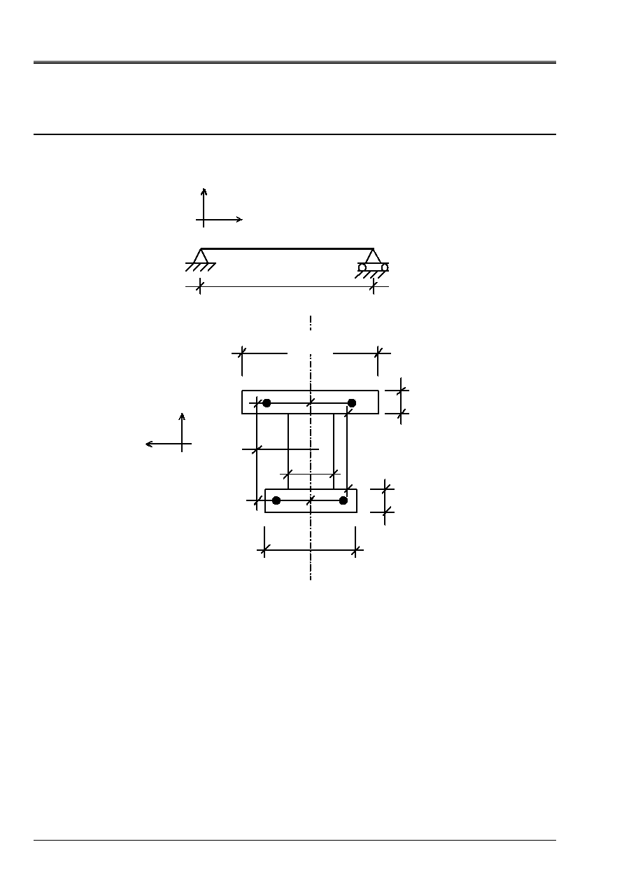
1.1 Geometry
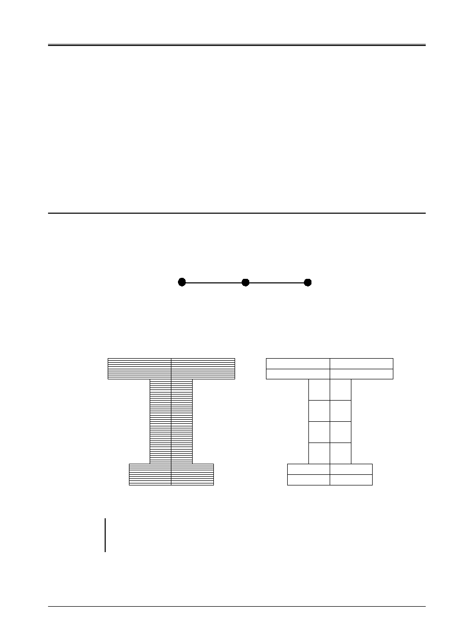
Beam in bending three points, defined by:
5 m
With
B
X
y
With a section in double T:
30 cm
5 cm
20 C m
10 cm
5 cm
20 cm
10 C m
10 C m
8 cm
8 cm
y
Z
O
12, 5 cm
12,5 cm
On this diagram, O is located at middle height of the section.
The total section of higher steels is 3.10
4
m
2
and that of lower steels is 4.10
4
m
2
.
1.2
Material properties
·
concrete: E = 2. 10
10
AP;
= 0.2;
= 2400 kg.m
3
;
= 10-5 K
1
·
steel: E = 2,1. 10
11
AP;
= 0.33;
= 7800 kg.m
3
;
= 10-5 K
1
1.3
Boundary conditions
Simple support in b: Dy = 0
Support “doubles” in a: dx = Dy = dz = 0 just as X-ray = ry = 0.
1.4 Loadings
Three loading cases are tested successively:
Loading 1: effort concentrated in the mediums of the beam, F = 10000 NR
Loading 2: actual weight of the beam, G = 9,8 Mr. S
2
Loading 3: homogeneous heating of the beam T = 100 K
Code_Aster
®
Version
6.2
Titrate:
SSLL111 - Elements of multifibre beam (straight lines)
Date:
05/11/02
Author (S):
S. MILL, L. DAVENNE, F.GATUINGT
Key
:
V3.01.111-A
Page:
3/8
Manual of Validation
V3.01 booklet: Linear statics of the linear structures
HT-66/02/001/A
2
Reference solution
Calculations of reference are carried out starting from a simple elastic design in RdM.
2.1 Center
rubber band
In pure bending, for an elastic behavior, the neutral axis passes by the elastic center
(barycentre of the sections balanced by the modules of materials):
C
such as
=
S
dS
CM
E
0
One determines initially the position of the centers of gravity of the concrete alone
G
B
and of steel alone
G
has
by
report/ratio at the point O.
y
G
B
=
0,125
×
0,3
×
0,05
-
0,125
×
0,2
×
0,05
0,2
×
0,05
+
0,1
×
0,2
+
0,3
×
0,05
=
1,38888.10
-
2
m
y
G
has
=
0,125
×
3
-
0,125
×
4
3
+
4
= -
1,78571.10
-
2
m
Z
G
has
=
Z
G
B
=
0 m
One can then determine the position compared to O of the elastic center
C
.
B
B
has
has
B
B
B
has
has
has
S
E
S
E
OG
S
E
OG
S
E
OC
+
+
=
The concrete section
S
B
is 0,045 m
2
and the steel section
S
has
is 7.10
4
m
2
. The Young modulus of
concrete is 2.10
10
MPa and that of steel 21.10
10
MPa. One thus has
y
C
=
2
×
0,045
×
1,38888
-
21
×
7.10
-
4
×
1,78571
2
×
0,045
+
21
×
7.10
-
4
=
0,94317.10
-
2
m
Z
C
=
0 m
2.2 Moments
quadratic
The quadratic moments of the rectangular concrete sections are calculated by the formula
following:
2
3
12
D
H
B
bh
×
×
+
Where, B represents the width, H the height and D the distance from the center of gravity of the section by report/ratio
with the axis for which one calculates the moment.
One then obtains the quadratic moment of the concrete section compared to axis Z passing by
center elastic:
(
)
(
)
(
)
(
)
(
)
(
)
4
3
2
2
3
2
2
3
2
2
3
10
.
4547
,
0
10
.
94317
,
0
125
,
0
05
,
0
2
,
0
12
05
,
0
2
,
0
10
.
94317
,
0
2
,
0
1
,
0
12
2
,
0
1
,
0
10
.
94317
,
0
125
,
0
05
,
0
3
,
0
12
05
,
0
3
,
0
m
I
concrete
-
-
-
-
=
+
×
+
×
+
×
+
×
+
-
×
+
×
=
Code_Aster
®
Version
6.2
Titrate:
SSLL111 - Elements of multifibre beam (straight lines)
Date:
05/11/02
Author (S):
S. MILL, L. DAVENNE, F.GATUINGT
Key
:
V3.01.111-A
Page:
4/8
Manual of Validation
V3.01 booklet: Linear statics of the linear structures
HT-66/02/001/A
Inertias of steels are calculated by the following formula:
4
64
+
S
×
D
2
S
×
D
2
Where,
represent the diameter of steel, S the steel section and D the distance from the center of gravity from
section compared to the axis for which one calculates the moment. The diameter of steels being small, one
neglect the first term.
One then obtains the quadratic moment of the steel sections compared to axis Z passing by the center
rubber band:
3.10
-
4
×
(0,125
-
0,94317.10
-
2
)
2
+
4.10
-
4
×
(0,125
+
0,94317.10
-
2
)
2
=
0,1124.10
-
4
m
4
For the complete section of the beam, the quadratic moment balanced by the Young moduli of
materials is:
I.E.(internal excitation)
=
2.10
10
×
0,4547.10
-
3
+
21.10
10
×
0,1124.10
-
4
=
11,4544.10
6
Pa.m
4
2.3
Loading case 1
In the case of load 1 (loading concentrated in the middle of the beam), the arrow is calculated by
formulate following RDM:
I.E.(internal excitation)
L
F
F
48
3
×
=
What gives the arrow:
F
=
10000
×
5
3
48
×
11,4544.10
6
=
2,2735.10
-
3
m
One can also calculate the following generalized efforts:
·
the shearing action at the beginning of the beam (left left) is worth
F
2
=
5000 NR
,
·
the bending moment in the middle of the beam is worth:
F
×
L
4
=
1,25.10
4
N.m
.
2.4
Loading case 2
In the case of load 2 (actual weight of the beam), the arrow is calculated by the formula of RDM
following:
F
=
5
×
p
×
L
4
384 I.E.(internal excitation)
where
p
is the linear load due to the weight of materials:
p
=
G (
has
S
has
+
B
S
B
)
=
9,8
×
(2800
×
7.10
-
4
+
2400
×
0,045)
=
1111,9 NR .m
-
1
What gives the arrow:
F
=
5
×
1111,9
×
5
4
384
×
11,4544.10
6
=
7,9.10
-
4
m
Code_Aster
®
Version
6.2
Titrate:
SSLL111 - Elements of multifibre beam (straight lines)
Date:
05/11/02
Author (S):
S. MILL, L. DAVENNE, F.GATUINGT
Key
:
V3.01.111-A
Page:
5/8
Manual of Validation
V3.01 booklet: Linear statics of the linear structures
HT-66/02/001/A
2.5
Loading case 3
In the case of load 3 (homogeneous front elevation in temperature), the beam being isostatic and them
expansion factors of the concrete and steel being identical, the solution is simple:
The generalized stresses and efforts are null.
The lengthening of the beam is:
L
=
×
L
×
T
What gives with the values of our case:
L
=
10
-
5
×
5
×
100
=
5.10
-
3
m
3 Modeling
3.1
Characteristics of modeling
Longitudinal mesh of the beam:
We have 3 nodes and two elements
(POU_D_EM)
.
With
B
C
The concrete part of the cross section of the beam is with a grid (
AFFE_SECT
) while steels
are given directly in the form of 4 specific fibers in
AFFE_CARA_ELEM
(
AFFE_PONCT
).
Two mesh of the concrete part is tested in the case of load 1. The fine mesh consists of
120 fibers and the coarse mesh consists of 16 fibers:
Note:
The problem being 2D, only one fiber in the width could seem sufficient
(multi-layer), but that would result in having null terms in the matrix of rigidity
(the own inertia of fibers not being taken into account) and with an error at the time of the resolution of
system of equations.
Code_Aster
®
Version
6.2
Titrate:
SSLL111 - Elements of multifibre beam (straight lines)
Date:
05/11/02
Author (S):
S. MILL, L. DAVENNE, F.GATUINGT
Key
:
V3.01.111-A
Page:
6/8
Manual of Validation
V3.01 booklet: Linear statics of the linear structures
HT-66/02/001/A
3.2 Functionalities
tested
Controls
CREA_MAILLAGE
CREA_GROUP_MA
AFFE_MODELE
MESH
“MECHANICAL”
“POU_D_EM”
DEFI_MATERIAU
“ELAS”
AFFE_MATERIAU
GROUP_MA
MATER
AFFE_CARA_ELEM
BEAM
GROUP_MA
SECTION
ORIENTATION
GROUP_MA
CARA
“ANGL_VRIL”
AFFE_SECT
GROUP_MA
MAILLAGE_SECT
TOUT_SECT
“YES”
COOR_AXE_POUTRE
NAME
AFFE_FIBER
GROUP_MA
“SURFACE”
CARA
VALE
COOR_AXE_POUTRE
NAME
AFFE_CHAR_MECA
MODEL
DDL_IMPO
GROUP_NO
FORCE_NODALE
GROUP_NO
GRAVITY
TEMP_CALCULEE
MECA_STATIQUE
MODEL
CHAM_MATER
CARA_ELEM
EXCIT
CHARGE
CALC_ELEM
REUSE
RESULT
MODEL
CHAM_MATER
CARA_ELEM
OPTION
EFGE_ELNO_DEPL
EXCIT
CALC_NO
REUSE
RESULT
OPTION
EFGE_NOEU_DEPL
Code_Aster
®
Version
6.2
Titrate:
SSLL111 - Elements of multifibre beam (straight lines)
Date:
05/11/02
Author (S):
S. MILL, L. DAVENNE, F.GATUINGT
Key
:
V3.01.111-A
Page:
7/8
Manual of Validation
V3.01 booklet: Linear statics of the linear structures
HT-66/02/001/A
4 Results
4.1
Loading case 1
Reference
Modeling Ar
Relative error %
Arrow
(fine mesh)
2,2735 10
3
2,2740
10
3
0,02
Arrow
(coarse mesh)
2,2735 10
3
2,2956
10
3
1,0
(1)
Sharp effort
(supports A)
5000
2500
0,0
(2)
Bending moment
(Medium) 1,25
10
4
6,25
10
3
0,0
(2)
1) Calculations are carried out without taking into account the own inertia of each fiber. Results
show that it is not nevertheless very useful to hold account of it because the difference between one
coarse mesh and a fine mesh is not obvious.
The mesh of the section does not need to be very fine to have precise results (in
elasticity).
2) The option
EFGE_NOEU_DEPL
used to calculate the efforts generalized with the nodes does one
average of the generalized efforts of all the elements connected to the node. In our case,
we have 2 superimposed elements of beam (for the concrete, for steel), the efforts
calculated are thus divided by 2.
If one adds the values with efforts by element (
EFGE_ELNO_DEPL
) of the element concrete and of
the element steel, one finds the theoretical values well.
Note:
If one makes a calculation of arrow by taking O (middle height) like reference axis to the place
elastic center (
COOR_AXE_POUTRE
), the relative error on the arrow is 0,2% here (bus it
center elastic is practically with middle height (see 1.2.1).
4.2
Loading case 2
Reference
Modeling Ar
Relative error %
Arrow
(fine mesh)
7,900 10
4
7,902
10
4
0,02
4.3
Loading case 3
Reference
Modeling Ar
Relative error %
Lengthening 5,00
10
3
5,00
10
3
0,0
Efforts 0,00
0,00
0,0

Code_Aster
®
Version
6.2
Titrate:
SSLL111 - Elements of multifibre beam (straight lines)
Date:
05/11/02
Author (S):
S. MILL, L. DAVENNE, F.GATUINGT
Key
:
V3.01.111-A
Page:
8/8
Manual of Validation
V3.01 booklet: Linear statics of the linear structures
HT-66/02/001/A
5
Summary of the results
The results obtained are in concord with the results of reference.