
Code_Aster
®
Version
5.0
Titrate:
SSLL404 - Buckling of an arch
Date:
23/09/02
Author (S):
J.M. PROIX, F. SOULIE
Key
:
V3.01.404-A
Page:
1/6
Manual of Validation
V3.01 booklet: Linear statics of the linear structures
HT-66/02/001/A
Organization (S):
EDF/AMA,
SAMTECH
Manual of Validation
V3.01 booklet: Linear statics of the linear structures
V3.01.404 document
SSLL404 - Buckling of an arch
Summary
The applicability of this test is the analysis of stability of the structures. The studied structure is an arch
bent by moments applied at the two ends; it is modelized by elements of beams
straight lines. The goal is to calculate the breaking values of the moments.
The interest of this test lies in the following aspects:
·
calculation of a geometrical matrix of rigidity for the elements
POU_D_E
.
·
test of the modal methods
MODE_ITER_SIMULT
and
MODE_ITER_INV
in stability
·
presence of close eigenvalues
The calculated clean loads are compared with values obtained analytically for a model of
beam of Euler-Bernoulli.
In this test, one also validates the option
RAYLEIGH
control
MODE_ITER_INV
.
Code_Aster
®
Version
5.0
Titrate:
SSLL404 - Buckling of an arch
Date:
23/09/02
Author (S):
J.M. PROIX, F. SOULIE
Key
:
V3.01.404-A
Page:
2/6
Manual of Validation
V3.01 booklet: Linear statics of the linear structures
HT-66/02/001/A
1
Problem of reference
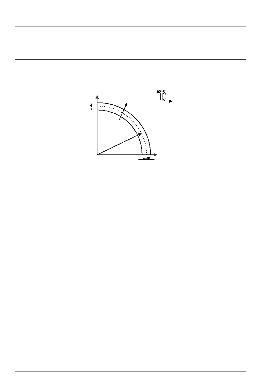
1.1 Geometry
X
Y
M
B
R
With
y
M
H
y
X
B
Radius of curvature
R = 0.3 m
Height of the profile
H = 0.015 m
Width of the profile
B = 0.002 m
Section
S = bh
1ère inertia of bending
I
X
= bh
3
/12
the 2nd inertia of bending
I
Y
= hb
3
/12
Inertia of torsion
J = hb
3
/3
1.2
Properties of materials
Young modulus
E = 7. E 10 NR/m ²
Poisson's ratio
= 0.3
Modulus of rigidity
G = E/2 (1+
)
1.3
Boundary conditions and loading
The beam Bi-is supported. One prevents the torsion of the section at ends A and B. to respect
the assumptions of the ideal model taken as reference, it is important that the moment is
constant and that the normal effort is null along the beam. This is why free it is left
displacement U according to X at the point B. the boundary conditions are:
At point a: U = v = W = 0;
Y
= 0
At point b: v = W = 0;
X
= 0
The initial state of stress which makes it possible to carry out the analysis of stability is obtained by imposing one
bending moment around axis Z:
At points A and b: M = 1 Nm
1.4 Conditions
initial
Without object in static analysis of stability.
Code_Aster
®
Version
5.0
Titrate:
SSLL404 - Buckling of an arch
Date:
23/09/02
Author (S):
J.M. PROIX, F. SOULIE
Key
:
V3.01.404-A
Page:
3/6
Manual of Validation
V3.01 booklet: Linear statics of the linear structures
HT-66/02/001/A
2
Reference solution
2.1
Method of calculation used for the reference solution
The reference solution is obtained analytically for a beam of Euler-Bernoulli. Aspects
theoretical are developed in the reference [bib1].
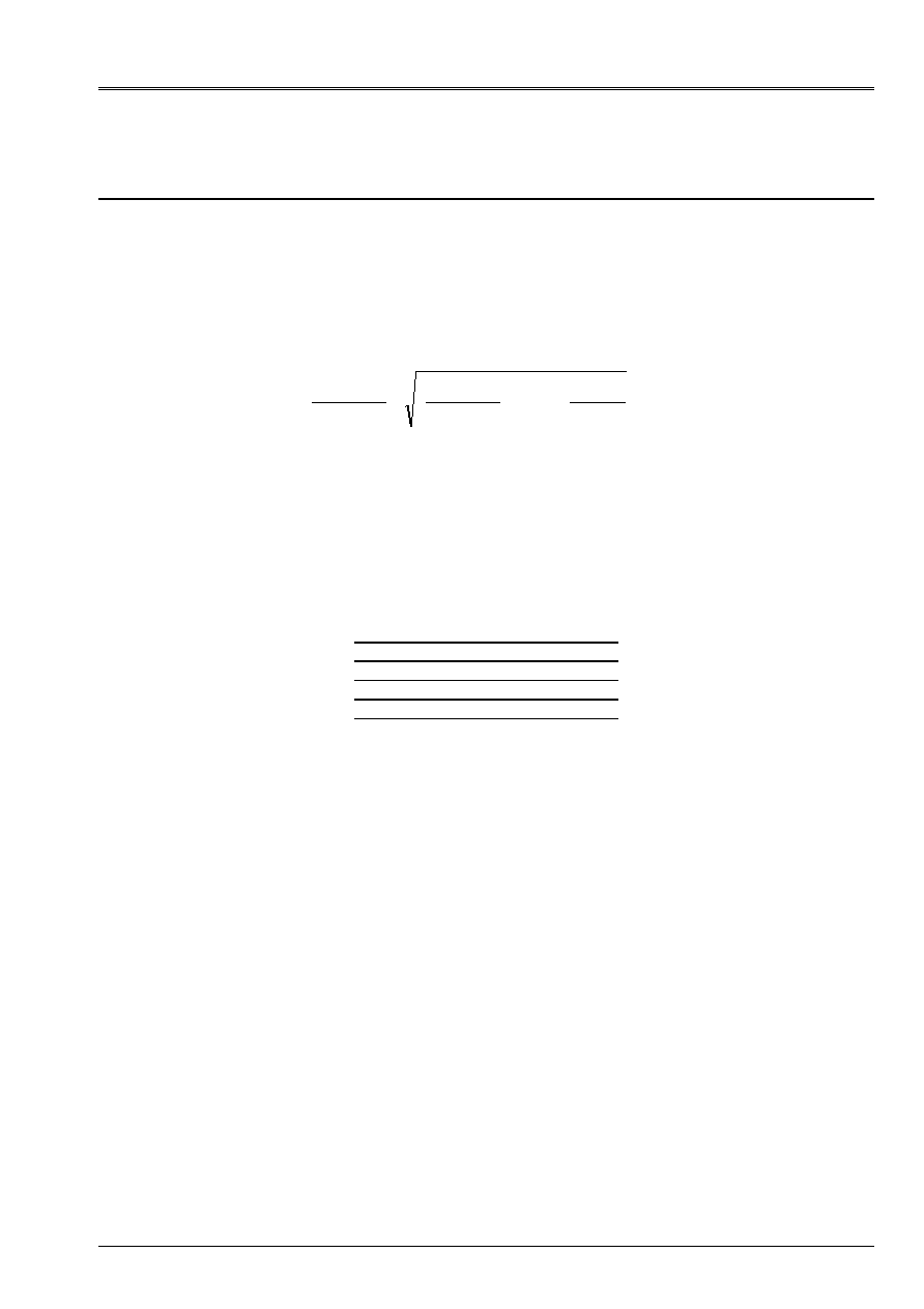
By using the notations of the paragraph [§1], the values criticize are given by the expression:
M
I.E.(internal excitation)
GJ
R
I.E.(internal excitation)
GJ
R
N I.E.(internal excitation) GJ
R
N
CR
X
X
X
= -
+
±
-
+
=
2
2
4
1 2 3
2
2
2
,….
The plus sign corresponds to positive moments such as they are indicated on the figure of [§1.1].
2.2
Results of reference
The first 5 critical loads are classified by command of increasing module.
Mode Moment criticizes (Nm)
1 2.86074
2 8.63207
3 8.78382
4 14.4147
5 14.5551
With Code_Aster, one finds the opposites of these critical loads (what is logical compared to
formulation of the problem to be solved).
2.3
Uncertainty on the solution
Analytical solution
2.4 References
bibliographical
[1]
TIMOSHENKO Stephen P., MANAGES James Mr., Theory off Elastic Stability, McGraw-Hill,
International Edition, 1963, pp. 313-318.
Code_Aster
®
Version
5.0
Titrate:
SSLL404 - Buckling of an arch
Date:
23/09/02
Author (S):
J.M. PROIX, F. SOULIE
Key
:
V3.01.404-A
Page:
4/6
Manual of Validation
V3.01 booklet: Linear statics of the linear structures
HT-66/02/001/A
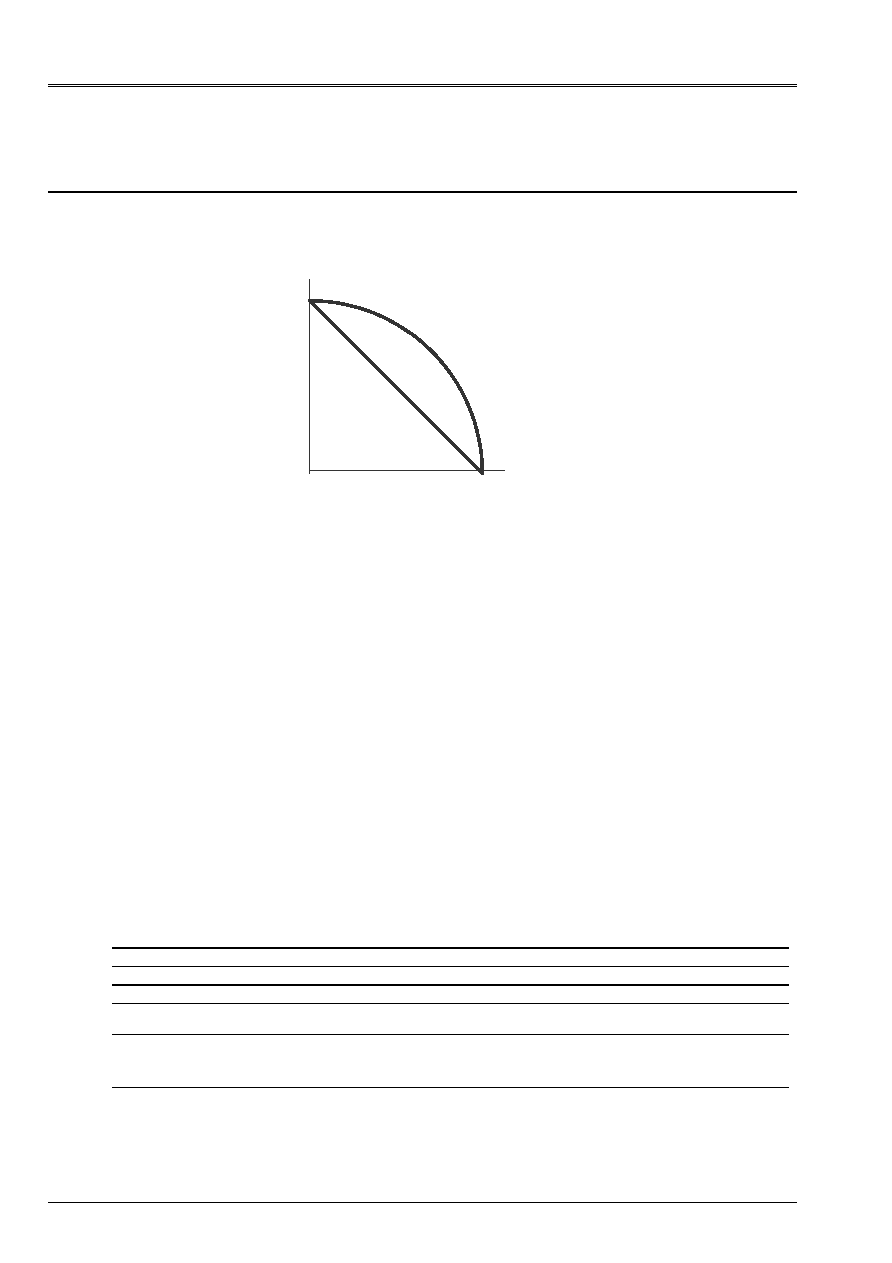
3 Modeling
With
3.1
Characteristics of modeling
X, DX
Y, DY
1
19
The arch is with a grid by means of elements of right beam of type
POU_D_E
.
Boundary conditions:
At point A such as X = R, Y = 0:
DX = DY = DZ = 0 and RY = 0
At the point B such as X = 0, Y = R:
DY = DZ = 0 and X-ray = 0
For the static analysis, unit moments around Z are defined in nodes 1 and 19.
3.2
Characteristics of the mesh
A number of nodes: 19
A number of meshs: 18 POU_D_E
3.3 Functionalities
tested
Controls
AFFE_MODELE
AFFE
MODELING
“POU_D_E”
AFFE_CHAR_MECA
DDL_IMPO
AFFE_CARA_ELEM
BEAM
CALC_MATR_ELEM
OPTION
“RIGI_GEOM”
“RIGI_MECA”
MODE_ITER_SIMULT
METHOD
“SORENSEN”
CALC_FREQ
OPTION
PLUS_PETITE'
NMAX_FREQ
MODE_ITER_INV
CALC_FREQ
OPTION
“NEAR”
CHAR_CRIT
CALC_MODE
OPTION
RAYLEIGH
Code_Aster
®
Version
5.0
Titrate:
SSLL404 - Buckling of an arch
Date:
23/09/02
Author (S):
J.M. PROIX, F. SOULIE
Key
:
V3.01.404-A
Page:
5/6
Manual of Validation
V3.01 booklet: Linear statics of the linear structures
HT-66/02/001/A
4
Results of modeling A
Critical load
4.1
MODE_ITER_SIMULT
with
METHOD = “SORENSEN”
Identification
N° critical load
Reference
(multiplied by - 1)
Code_Aster %
difference
1 2.86074
2.75137
3.823
2 8.63207
8.30613
3.776
3
8.78382 8.39554 4.420
4 14.4147
13.93216
3.348
5
14.5551 14.01104 3.738
4.2
MODE_ITER_INV
with
OPTION = “NEAR”
Identification
N° critical load
Reference
(multiplied by - 1)
Code_Aster %
difference
1 2.86074
2.75137
3.823
2 8.63207
8.30613
3.776
3 8.78382
8.39554
4.420
4 14.4147
13.93216
3.348
5 14.5551
14.01104
3.738

Code_Aster
®
Version
5.0
Titrate:
SSLL404 - Buckling of an arch
Date:
23/09/02
Author (S):
J.M. PROIX, F. SOULIE
Key
:
V3.01.404-A
Page:
6/6
Manual of Validation
V3.01 booklet: Linear statics of the linear structures
HT-66/02/001/A
5
Summary of the results
The methods of Sorensen and the iterations opposite give identical and satisfactory results
since the maximum change with the analytical solution is lower than 4.5%.On recalls than the solution
analytical takes into account the curvature of the structure.
Elements MEPOUCT could not be used in this test because the calculation of the matrix of rigidity
geometrical is not available for this type of element.