Code_Aster
®
Version
3
Titrate:
SSLP103 Calculation of
K
I
and
K
II
for a fissured circular plate
Date:
24/08/99
Author (S):
E. SCREWS
Key:
V3.02.103-A
Page:
1/6
Manual of Validation
V3.02 booklet: Linear statics of the plane systems
HI-75/96/016 - Ind A
Organization (S):
EDF/IMA/MN
Manual of Validation
V3.02 booklet: Linear statics of the plane systems
Document: V3.02.103
SSLP103 - Calculation of the coefficients of intensity of
stresses
K
I
and
K
II
for a circular plate
fissured in linear elasticity
Summary
It is about a test of breaking process in static linear elasticity for a two-dimensional problem. One
consider a circular plate fissured (with a tilted fissure of 30 degrees compared to the axis of
X-coordinates) for which one calculates:
·
coefficients of intensity of stresses
K
I
and
K
II
,
·
the rate of refund of energy G starting from the formula of IRWIN.
The interest of the test is to know the analytical solution which gives the coefficients of intensity of stresses and
to have a tilted fissure.
This test includes/understands a modeling which treats successively the plane strains and the plane stresses
(elements of continuous mediums).
The numerical results do not deviate more than 1 to 2% from the values of reference.
Code_Aster
®
Version
3
Titrate:
SSLP103 Calculation of
K
I
and
K
II
for a fissured circular plate
Date:
24/08/99
Author (S):
E. SCREWS
Key:
V3.02.103-A
Page:
2/6
Manual of Validation
V3.02 booklet: Linear statics of the plane systems
HI-75/96/016 - Ind A
1
Problem of reference
1.1 Geometry
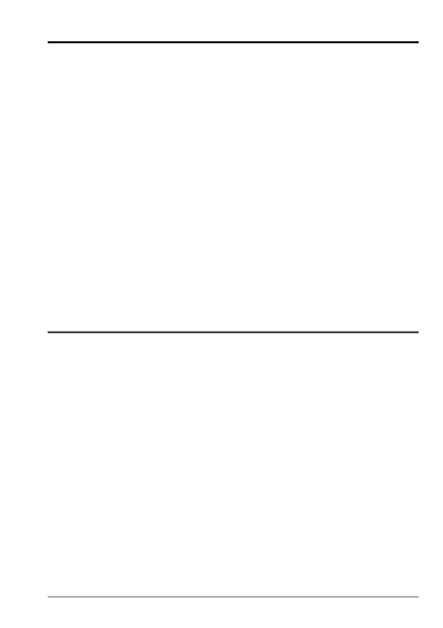
It is about a circular plate of radius 0A = 100 mm, with a tilted fissure of 30 degrees by
report/ratio with the X-axis.
Y
X
0
30°
With
1.2
Material properties
The characteristics of material are as follows:
E = 200.000 MPa
= 0.3
1.3
Boundary conditions and loadings
Displacements are imposed on the contour of the plate. They result from the analytical solution
singular in mixed mode (with
K
I
= 2. and
K
II
= 1.).
Code_Aster
®
Version
3
Titrate:
SSLP103 Calculation of
K
I
and
K
II
for a fissured circular plate
Date:
24/08/99
Author (S):
E. SCREWS
Key:
V3.02.103-A
Page:
3/6
Manual of Validation
V3.02 booklet: Linear statics of the plane systems
HI-75/96/016 - Ind A
2
Reference solution
2.1
Method of calculation used for the reference solution
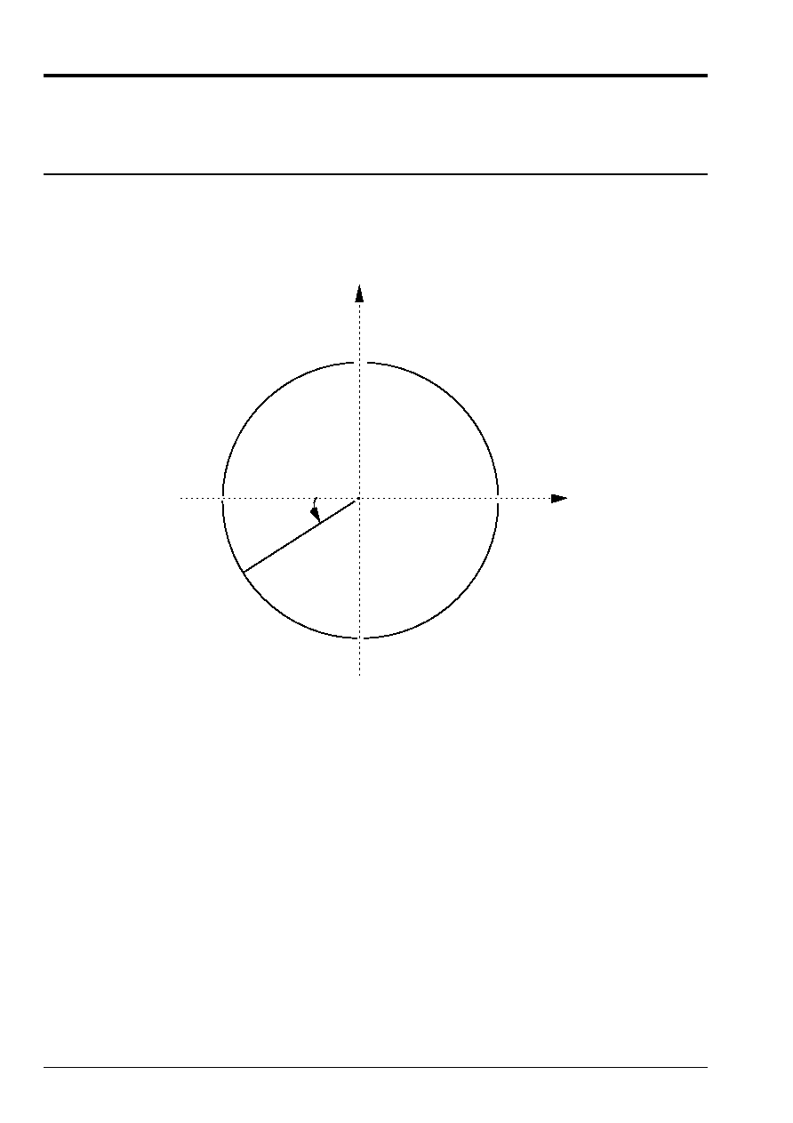
X
2
Y
M
X
1
X
O
R
In plane strains or plane stresses, the distribution of displacements is given in it
identify (0, X
1
, X
2
) by:
(
)
(
)
(
)
(
)
U
E
R
K
K
K
K
U
E
N
K
K
K
K
I
II
I
II
1
2
1
2
2
2
2
1
2
2
2
2
= +
-
+
-
+
= +
-
-
+
-
cos
cos
sin
cos
sin
cos
cos
cos
with
K
= -
3 4
in plane deformations
K
= - +
3
1
in plane stresses
or in the reference mark (O, X, Y) by:
U
U
U
U
U
U
X
Y
=
-
=
+
cos
sin
sin
cos
1
2
1
2
On the contour of the plate, one a: R = 0A = 100 Misters.
One chooses to take
K
I
= 2. and
K
II
= 1. and to impose displacements on the contour of the plate
circular.
2.2
Results of reference
K
I
= 2.
K
II
= 1.
G = 2.275 10
5
in plane deformations
G = 2.5 10
5
in plane stresses
2.3 References
bibliographical
[1]
Breaking process H.D. BUI Fragile - ED. Masson 1978
Code_Aster
®
Version
3
Titrate:
SSLP103 Calculation of
K
I
and
K
II
for a fissured circular plate
Date:
24/08/99
Author (S):
E. SCREWS
Key:
V3.02.103-A
Page:
4/6
Manual of Validation
V3.02 booklet: Linear statics of the plane systems
HI-75/96/016 - Ind A
3 Modeling
With
3.1
Characteristics of modeling
Calculation is carried out in plane stresses (
C_PLAN
) then in plane deformations (
D_PLAN
).
With
0
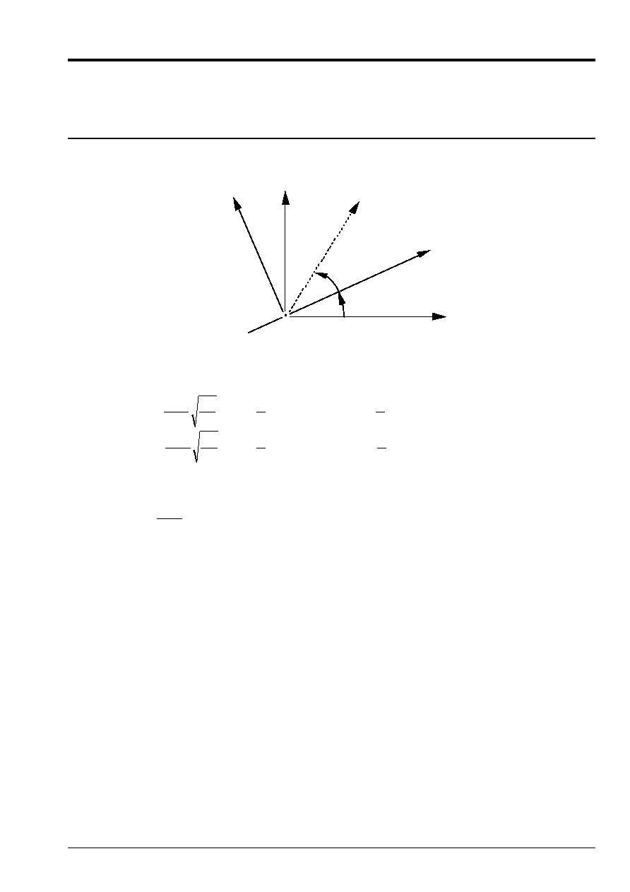
3.2
Characteristics of the mesh
A number of nodes: 737
A number of meshs and types: 204 meshs QUAD8, 30 meshs TRIA6
3.3 Functionalities
tested
Controls
Keys
CALC_G_THETA
CALC_K_G
U4.63.03
CALC_G_THETA
CALC_G
U4.63.03
Code_Aster
®
Version
3
Titrate:
SSLP103 Calculation of
K
I
and
K
II
for a fissured circular plate
Date:
24/08/99
Author (S):
E. SCREWS
Key:
V3.02.103-A
Page:
5/6
Manual of Validation
V3.02 booklet: Linear statics of the plane systems
HI-75/96/016 - Ind A
4
Results of modeling A
4.1 Values
tested
The values tested are the coefficients of intensity of stresses
K
I
and
K
II
and the rate of refund
of energy G calculated by the formula of IRWIN:
Identification
Reference
Aster
% difference
Plane stresses
K
I
2.0
2.0067
0.33
K
II
1.0
0.9877
1.23
G
2.5 10
- 5
2.5213 10
- 5
0.85
Plane deformations
K
I
2.0
2.0030
0.15
K
II
1.0
0.9960
0.39
G
2.275 10
- 5
2.2968 10
- 5
0.96
4.2 Remarks
(
) (
)
(
)
The formula of IRWIN gives:
in plane deformations
and
in plane stresses
G
E
K
K
G
E K
K
I
II
I
II
= -
+
=
+
1
1
2
2
2
2
2
Calculations are carried out with a crown of lower integration of radius 10.0 and radius
superior 20.0.
4.3 Parameters
of execution
Version: 3.06
Machine: CRAY C98
System: UNICOS
8.0
Overall dimension memory:
8 MW
Time CPU To use:
22 seconds

Code_Aster
®
Version
3
Titrate:
SSLP103 Calculation of
K
I
and
K
II
for a fissured circular plate
Date:
24/08/99
Author (S):
E. SCREWS
Key:
V3.02.103-A
Page:
6/6
Manual of Validation
V3.02 booklet: Linear statics of the plane systems
HI-75/96/016 - Ind A
5
Summaries of the results
Numerical values of the coefficients of intensity of stresses and the rate of refund of energy
do not deviate more than 1 to 2% from the values of reference, which is satisfactory.
The mesh could be improved, in particular in the vicinity of the bottom of fissure.