
Code_Aster
®
Version
6.0
Titrate:
SSLP304 - Orthotropic square plate in traction
Date:
12/12/02
Author (S):
J.M. PROIX, J.F. BILLAUD
Key
:
V3.02.304-A
Page:
1/10
Manual of Validation
V3.02 booklet: Linear statics of the plane systems
HT-66/02/001/A
Organization (S):
EDF-R & D/AMA, CETIM
Manual of Validation
V3.02 booklet: Linear statics of the plane systems
V3.02.304 document
SSLP304 - Orthotropic square plate in traction
uniaxial out of the axes of orthotropism
Summary:
This test represents the static calculation of a square plate, out of orthotropic elastic material, of which axes
othotropie are tilted 30 degrees compared to the basic edge, subjected to a uniaxial traction. It allows
to validate the good taking into account of orthotropic elastic materials and the change of associated reference mark.
4 modelings are used:
C_PLAN
with meshs
QUAD8
and
TRIA6
, in a first reference mark,
C_PLAN
in a second reference mark,
COQUE_3D
with meshs
QUAD9
and
TRIA7
, in small displacements and
COQUE_3D
in
great displacements. Displacements and the stresses obtained are compared with a reference solution
analytical.
The first two modelings of this test result from the validation independent of version 3 of
Code_Aster (linear static batch).
Code_Aster
®
Version
6.0
Titrate:
SSLP304 - Orthotropic square plate in traction
Date:
12/12/02
Author (S):
J.M. PROIX, J.F. BILLAUD
Key
:
V3.02.304-A
Page:
2/10
Manual of Validation
V3.02 booklet: Linear statics of the plane systems
HT-66/02/001/A
1
Problem of reference
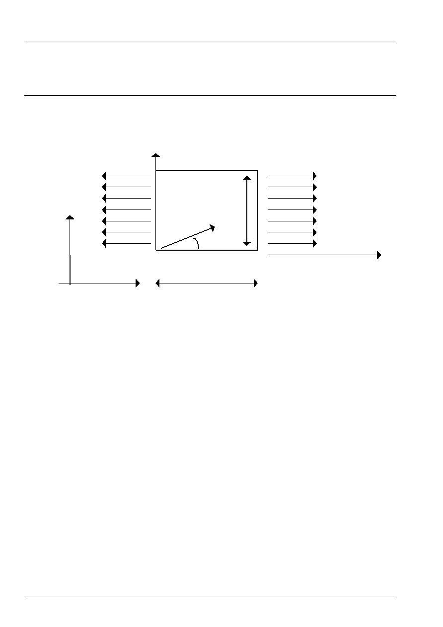
1.1 Geometry
A square plate, made up of a tilted orthotropic material of 30 degrees compared to edge AB.
With B = 1 m, unspecified thickness (plane stresses), angle of orthotropism:
= 30 degrees.
1.2
Properties of materials
The properties of materials constituting the plate are:
orthotropic rubber band:
E_L = 4.E10 AP
E_T = 1.E10 AP
G_LT = 0.45E10 AP
G_TN = 0.35E10 AP
NU_LT = 0.075
The axis L is tilted 30 degrees compared to AB.
1.3
Boundary conditions and loadings
·
At point a: DX = 0, DY = 0
·
At point b: DX = 0,
·
Linear loading distributed: Fx = 10
4
AP on BC
·
Linear loading distributed: Fx = - 10
4
AP on DA
1.4 Conditions
initial
Without object.
With
B
B
B
L
y
y
D
C
X

Code_Aster
®
Version
6.0
Titrate:
SSLP304 - Orthotropic square plate in traction
Date:
12/12/02
Author (S):
J.M. PROIX, J.F. BILLAUD
Key
:
V3.02.304-A
Page:
3/10
Manual of Validation
V3.02 booklet: Linear statics of the plane systems
HT-66/02/001/A
2
Reference solution
2.1
Method of calculation used for the reference solution
Analytical solution, obtained with the assumption of uniaxiality of the stresses:
0
)
,
(
)
,
(
)
,
(
)
,
(
=
=
=
=
y
X
y
X
y
X
F
y
X
zz
yy
xy
X
xx
maybe in the reference mark (A, L, T):
X
LT
X
TT
X
L
csF
y
X
F
S
y
X
F
C
y
X
-
=
=
=
)
,
(
)
,
(
,
)
,
(
2
2
By the orthotropic law of behavior elastic, by using conventions of Code_Aster in what
relate to NU_LT, (cf document of use of the control
DEFI_MATERIAU
[§3.5.2]), one obtains
directly (see for example [bib1]):
()
X
X
xx
E
F
y
X
=
,
,
yy
xy
X
X
X y
E F
(,)
,
= -
2
xy
X
X
X
X y
E F
(,)
=
with:
1
1
2
4
4
2 2
E
C
E
S
E
C S G
E
X
L
T
LT
LT
T
()
=
+
+
-
xy
X
LT
T
L
T
LT
E
C
S
E
C S
E
E
G
()
(
)
=
+
-
+
-
4
4
2 2
1
1
1
(
)
sin
cos
2
1
2
)
(
2
2
2
2
=
=
-
-
+
-
-
=
S
C
G
E
S
C
E
S
E
C
Cs
E
LT
T
LT
T
L
X
y
with
As the deformations are uniform in the plate one obtains, by integration, displacements
in the reference mark (A, X, y):
U X y
X
X
xx
(,)
.
=
U X y
y
X
y
yy
xy
(,)
.
.
=
+
2
2.2
Results of reference
Displacements in the reference mark (A, X, y) (in m):
Not B
C
D
U
X
0.
5.917 10
7
5.917
10
7
U
X
2.292 10
7
5.028
10
7
7.319
10
7
Code_Aster
®
Version
6.0
Titrate:
SSLP304 - Orthotropic square plate in traction
Date:
12/12/02
Author (S):
J.M. PROIX, J.F. BILLAUD
Key
:
V3.02.304-A
Page:
4/10
Manual of Validation
V3.02 booklet: Linear statics of the plane systems
HT-66/02/001/A
Stresses in the reference mark related to the orthotropism:
L
X y
(,)
= 7500Pa,
TT
X y
(,)
= 2500Pa,
LT
X y
(,)
= 4330.127Pa
2.3
Uncertainty on the solution
Analytical solution
2.4 References
bibliographical
[1]
GAY D: “Composite Materials”; 3
ème
edition, Hermès
3 Modeling
With
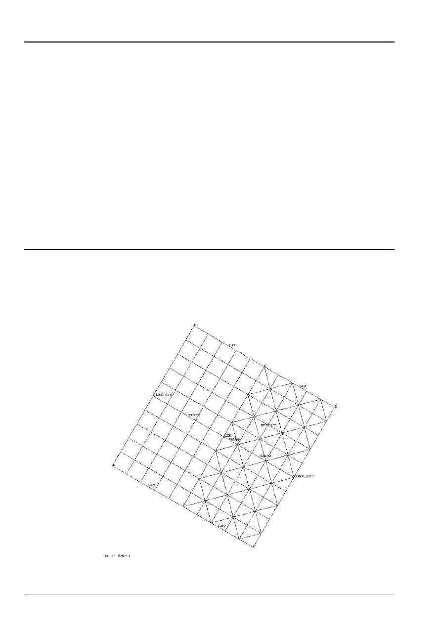
3.1
Characteristics of modeling
Modeling C_PLAN. The plate is turned of - 30 degrees around Z, i.e. axis X total
is colinéaire with the axis of orthotropism L. the boundary conditions and loadings, to apply in
identify (A, X, y) related to the plate, are thus projected on the total reference mark (A, X, Y) (use of
LIAISON_DDL in B).
Code_Aster
®
Version
6.0
Titrate:
SSLP304 - Orthotropic square plate in traction
Date:
12/12/02
Author (S):
J.M. PROIX, J.F. BILLAUD
Key
:
V3.02.304-A
Page:
5/10
Manual of Validation
V3.02 booklet: Linear statics of the plane systems
HT-66/02/001/A
3.2
Characteristics of the mesh
A number of nodes: 391
A number of meshs and types: 50 QUAD8, 100 TRIA6
3.3 Functionalities
tested
Controls
AFFE-MODELE
“AFFE”
MODELING = “C_PLAN”
AFFE_CARA_ELEM
SOLID MASS
ANGL_REP = 0
AFFE_CHAR_MECA_F FORCE_CONTOUR FX,
FY
AFFE_CHAR_MECA_F LIAISON_DDL
DEFI_MATERIAU ELAS_ORTH
MODI_REPERE
DEFI_REPERE
IDENTIFY = “USER”
3.4 Values
tested
Value Identification Reference
Aster %
difference
Ux (c) = Ux (D)
DX (C)
5.917 10
7
5.9167
10
7
0.007
Uy (B) DY
(B)
2.292 10
7
2.2916
10
7
0.01
Uy (C) DY
(C)
5.028 10
7
5.0279
10
7
0.001
Uy (D)
DY (D)
7.319 10
7
7.3196
10
7
0.008
Sigma L
SIXX (any point)
7500
7500.4
0.006
Sigma TT
SIYY (any point)
2500
2500.3
0.01
Sigma L
SIXY (any point)
4300.127
433.06
0.01
Code_Aster
®
Version
6.0
Titrate:
SSLP304 - Orthotropic square plate in traction
Date:
12/12/02
Author (S):
J.M. PROIX, J.F. BILLAUD
Key
:
V3.02.304-A
Page:
6/10
Manual of Validation
V3.02 booklet: Linear statics of the plane systems
HT-66/02/001/A
4 Modeling
B
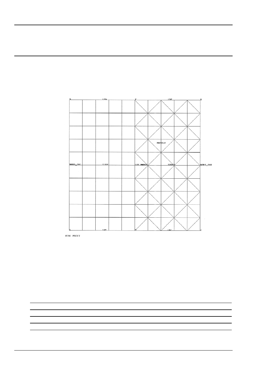
4.1
Characteristics of modeling
Modeling C_PLAN. The plate is parallel to the total axes, i.e. total axis X is
colinéaire with axis X. It is thus the axis of orthotropism L which is to be directed (using the key word
SOLID MASS
of
AFFE_CARA_ELEM
).
4.2
Characteristics of the mesh
A number of nodes: 391
A number of meshs and types: 50 QUAD8, 100 TRIA6
4.3 Functionalities
tested
Controls Key word
factor
Key word
AFFE_MODELE
AFFE
MODELING = “C_PLAN”
AFFE_CARA_ELEM
SOLID MASS
ANGL_REP = 30
AFFE_CHAR_MECA_F FORCE_CONTOUR
FX,
FY
DEFI_MATERIAU ELAS_ORTH
MODI_REPERE
DEFI_REPERE
IDENTIFY = “USER”
Code_Aster
®
Version
6.0
Titrate:
SSLP304 - Orthotropic square plate in traction
Date:
12/12/02
Author (S):
J.M. PROIX, J.F. BILLAUD
Key
:
V3.02.304-A
Page:
7/10
Manual of Validation
V3.02 booklet: Linear statics of the plane systems
HT-66/02/001/A
4.4 Values
tested
Value Identification
Reference
Aster %
difference
Ux (c) = Ux (D)
DX (C)
5.917 10
7
5.9167
10
7
0.006
Uy (B) DY
(B)
2.292 10
7
2.29166
10
7
0.015
Uy (C) DY
(C)
5.028 10
7
5.0277
10
7
0.005
Uy (D)
DY (D)
7.319 10
7
7.3194
10
7
0.006
Sigma L
SIXX (any point)
7500
7500
0.
Sigma TT
SIYY (any point)
2500
2500
0.
Sigma L
SIXY (any point)
4300.127
4330.127
0.
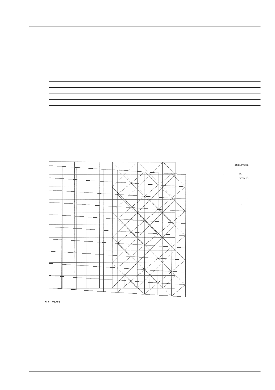
4.5 Remarks
Pace of the deformation: nonsymmetrical because of the orthotropism.
Code_Aster
®
Version
6.0
Titrate:
SSLP304 - Orthotropic square plate in traction
Date:
12/12/02
Author (S):
J.M. PROIX, J.F. BILLAUD
Key
:
V3.02.304-A
Page:
8/10
Manual of Validation
V3.02 booklet: Linear statics of the plane systems
HT-66/02/001/A
5 Modeling
C
5.1
Characteristics of modeling
Modeling COQUE_3D. The plate is parallel to the total axes, i.e. total axis X is
colinéaire with axis X. It is thus the axis of orthotropism L which is to be directed (using the key word
SOLID MASS
of
AFFE_CARA_ELEM
). The mesh is identical to that of modeling B.
5.2
Characteristics of the mesh
A number of nodes: 541
A number of meshs and types: 50 QUAD9, 100 TRIA7
5.3 Functionalities
tested
Controls Key word
factor
Key word
AFFE_MODELE
AFFE
MODELING = “COQUE_3D”
AFFE_CARA_ELEM
HULL
ANGL_REP = 30
AFFE_CARA_ELEM
HULL
THICK = 1
AFFE_CHAR_MECA_F FORCE_ARETE
FX,
FY
DEFI_MATERIAU ELAS_ORTH
5.4 Values
tested
Value Identification
Reference Aster %
difference
Ux (c) = Ux (D)
DX (C)
5.917 10
7
5.9167
10
7
0.006
Uy (B) DY
(B)
2.292 10
7
2.29166
10
7
0.015
Uy (C) DY
(C)
5.028 10
7
5.0277
10
7
0.005
Uy (D)
DY (D)
7.319 10
7
7.3194
10
7
0.006
Sigma L
SIXX (any point)
7500
7500
0.
Sigma TT
SIYY (any point)
2500
2500
0.
Sigma L
SIXY (any point)
4300.127
4330.127
0.
Code_Aster
®
Version
6.0
Titrate:
SSLP304 - Orthotropic square plate in traction
Date:
12/12/02
Author (S):
J.M. PROIX, J.F. BILLAUD
Key
:
V3.02.304-A
Page:
9/10
Manual of Validation
V3.02 booklet: Linear statics of the plane systems
HT-66/02/001/A
6 Modeling
D
6.1
Characteristics of modeling
Modeling COQUE_3D in great displacements. The plate is parallel to the total axes,
i.e. total axis X is colinéaire with axis X. It is thus the axis of orthotropism L which is to be directed
(using the key word
SOLID MASS
of
AFFE_CARA_ELEM
). The mesh is identical to that of
modeling B.
6.2
Characteristics of the mesh
A number of nodes: 541
A number of meshs and types: 50 QUAD9, 100 TRIA7
6.3 Functionalities
tested
Controls Key word
factor
Key word
AFFE_MODELE
AFFE
MODELING = “COQUE_3D”
AFFE_CARA_ELEM
HULL
ANGL_REP = 30
AFFE_CARA_ELEM
HULL
THICK = 1
AFFE_CHAR_MECA_F FORCE_ARETE
FX,
FY
DEFI_MATERIAU ELAS_ORTH
STAT_NON_LINE COMP_ELAS
DEFORMATION=' GRENN_GR'
6.4 Values
tested
Value Identification
Reference Aster %
difference
Ux (c) = Ux (D)
DX (C)
5.917 10
7
5.9167
10
7
0.006
Uy (B) DY
(B)
2.292 10
7
2.29166
10
7
0.015
Uy (C) DY
(C)
5.028 10
7
5.0277
10
7
0.005
Uy (D)
DY (D)
7.319 10
7
7.3194
10
7
0.006
Sigma L
SIXX (any point)
7500
7499.99
0.001
Sigma TT
SIYY (any point)
2500
2499.93
0.003
Sigma L
SIXY (any point)
4300.127
4329.99
0.007

Code_Aster
®
Version
6.0
Titrate:
SSLP304 - Orthotropic square plate in traction
Date:
12/12/02
Author (S):
J.M. PROIX, J.F. BILLAUD
Key
:
V3.02.304-A
Page:
10/10
Manual of Validation
V3.02 booklet: Linear statics of the plane systems
HT-66/02/001/A
7
Summary of the results
The results of four modelings are very close to the analytical solution: to the maximum 0.015
% of variation for 4 modelings.
This test thus validates the taking into account of orthotropic elasticity.