Code_Aster
®
Version
5.0
Titrate:
SSLP311 - Biblio_65. Fissure central oblique in a plate
Date:
05/11/02
Author (S)
:
S. GRANET, I. CORMEAU, E. LECLERE
Key:
V3.02.311-A
Page:
1/8
Manual of Validation
V3.02 booklet: Linear statics of the plane systems
HT-66/02/001/A
Organization (S)
: EDF-R & D/AMA, CS IF
Manual of Validation
V3.02 booklet: Linear statics of the plane systems
V3.02.311 document
SSLP311 - Biblio_65. Fissure central oblique in
a finished rectangular plate, with two materials,
subjected to uniform traction
Summary:
This test results from the validation independent of version 3 in breaking process.
It is about a two-dimensional test in statics with Bi-material in the presence of an internal fissure of interface
oblique.
The behavior of the structure (Bi-material) is elastic linear isotropic.
The case test includes/understands four modelings in plane stresses in which the influence of the slope of
the fissure
is studied (4 cases).
Code_Aster
®
Version
5.0
Titrate:
SSLP311 - Biblio_65. Fissure central oblique in a plate
Date:
05/11/02
Author (S)
:
S. GRANET, I. CORMEAU, E. LECLERE
Key:
V3.02.311-A
Page:
2/8
Manual of Validation
V3.02 booklet: Linear statics of the plane systems
HT-66/02/001/A
1
Problem of reference
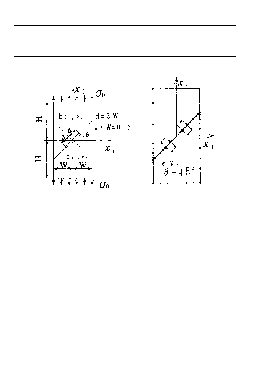
1.1 Geometry
4 values of the angle are considered
= 15°, 30°, 45° and 60°.
Other dimensions are selected such as H = 2W = 4a.
The value of A is worth 1.E-3 Mr.
1.2
Properties of materials
Material n° 1
Rubber band, linear, isotropic, Young modulus E1 = 2e+12 AP and Poisson's ratio
1 = 0,3.
Material n° 2
Rubber band, linear, isotropic, Young modulus E2 = 2e+11 AP and Poisson's ratio
2 = 0,3.
1.3
Boundary conditions and loading
·
The loading being autoéquilibré, one is satisfied to lock the 3 rigid modes:
UX = UY = 0 with the left lower corner of the complete model.
UY = 0 with the corner lower right of the complete model.
·
On the lower edge, we impose UY = 0
·
Loading: uniform voltage
yy =
0 on the higher edge:
The value of
0 are worth 100MPa.
Code_Aster
®
Version
5.0
Titrate:
SSLP311 - Biblio_65. Fissure central oblique in a plate
Date:
05/11/02
Author (S)
:
S. GRANET, I. CORMEAU, E. LECLERE
Key:
V3.02.311-A
Page:
3/8
Manual of Validation
V3.02 booklet: Linear statics of the plane systems
HT-66/02/001/A
2
Reference solution
2.1
Method of calculation used for the reference solution
Method of the elements of border, with quadratic elements [bib1].
The calculation of KI and KII is carried out by an integral of contour (integral M [bib2]) in which
the stresses and displacements calculated in the part intervene, as well as the stresses and
displacements deduced from analytically definite asymptotic solutions, in which KI and KII
are alternatively null. The calculation of K is also carried out by the method of virtual extension,
as comparison.
2.2
Results of reference
Method
On the left-hand side
On the right-hand side
= 15°
= 30°
= 45°
= 60°
= 15°
= 30°
= 45°
= 60°
integral FI
1,0115 0,7868 0,5211 0,2770 1,1266 0,9910 0,7646 0,4919
MR. FII
-
0,4434
-
0,6244
-
0,6723
-
0,5804
0,0862 0,2961 0,4056 0,4057
extension FI
1,0110 0,7864 0,5210 0,2769 1,1260 0,9904 0,7643 0,4919
virtual FII
-
0,4429
-
0,6240
-
0,6720
-
0,5801
0,0865 0,2960 0,4055 0,4056
In this table one a:
F
K
has
J
I II
J
J
=
=
0
,
The relation between the total rate of restitution of energy G and Kj is written as follows [bib3]:
(
)
()
(
)
µ
µ
µ
µ
µ
µ
µ
I
I
I
I
I
I
I
II
I
E
CH
G
K
K
= - +
=
=
+
=
+
+
=
+
+ +
=
+
3
1
1 2
2 1
1
2
1
1
1
1
16
1
1
2
2
2
1
1
1
2
2
2
2
2
,
ln
2.3
Uncertainty on the solution
Estimated at less than 0,1%.
2.4 References
bibliographical
[1]
Stress intensity Factor analysis off interface ace using boundary element method. Application
off contour-integral method. NR. MIYAZAKI, T. IKEDA, T.SODA and T. MUNAKATA.
Engng.Fract.Mechs., 45, n°5, 599-610, 1993.
[2]
Year analysis off interface aces between dissimilar isotropic materials using conservation
integrals in elasticity. J.F. YAU and T.C. CHANG. Engng.Fract.Mechs., 20, 423-432, 1984.
[3]
The strength off adhesive gaskets using the theory off aces. B. Mr. MALYSHEV and
R.L. SALGANIK. Int.J.Fract.Mech., 1, 114-128, 1965.
Code_Aster
®
Version
5.0
Titrate:
SSLP311 - Biblio_65. Fissure central oblique in a plate
Date:
05/11/02
Author (S)
:
S. GRANET, I. CORMEAU, E. LECLERE
Key:
V3.02.311-A
Page:
4/8
Manual of Validation
V3.02 booklet: Linear statics of the plane systems
HT-66/02/001/A
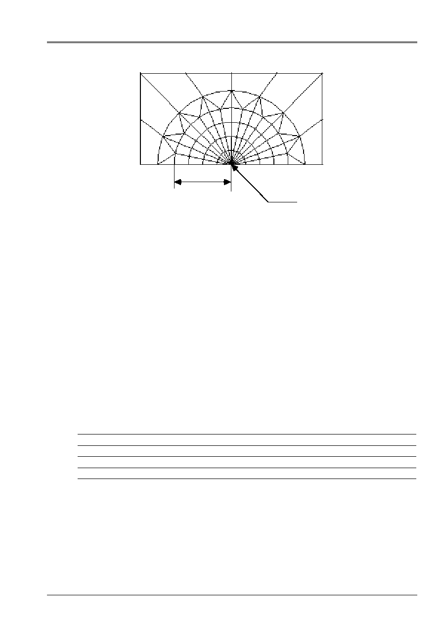
3
Modelings A, B, C, D
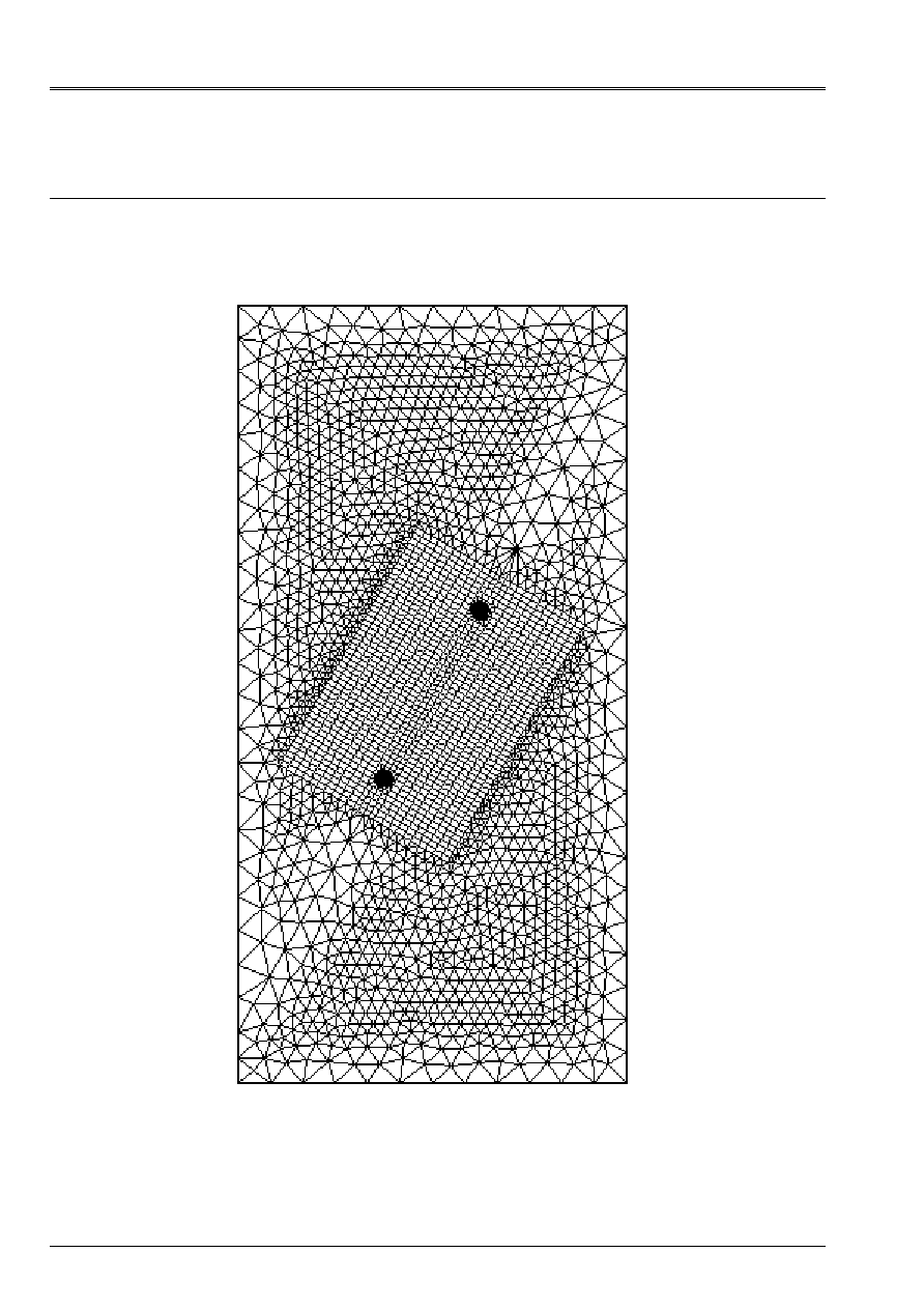
3.1
Characteristics of modeling
Various modelings are identical to share the slope of the fissure.
Complete mesh for an angle
from 60 °
Code_Aster
®
Version
5.0
Titrate:
SSLP311 - Biblio_65. Fissure central oblique in a plate
Date:
05/11/02
Author (S)
:
S. GRANET, I. CORMEAU, E. LECLERE
Key:
V3.02.311-A
Page:
5/8
Manual of Validation
V3.02 booklet: Linear statics of the plane systems
HT-66/02/001/A
radius
center
Zoom on the point of fissure
The radius is worth 7.5E-5 Mr.
There are four crowns defined by the control
CALC_THETA
:
crown 1: Rinf = 0.
Rsup = 1.875E-5m
crown 2: Rinf = 1.875E-5m
Rsup = 3.750E-5m
crown 3: Rinf = 3.750E-5m
Rsup = 5.625E-5m
crown 4: Rinf = 5.625E-5m
Rsup = 7.500E-5m
The direction of propagation is defined by: cos
, sin
3.2
Characteristics of the mesh
The mesh consists of 10676 nodes and 4584 elements, including 1392 elements QUA8 and 3168
elements TRI6.
3.3 Functionalities
tested
Controls
AFFE_MODELE
MECHANICS
C_PLAN
ALL
MECA_STATIQUE
AFFE_CHAR_MECA
FORCE_CONTOUR
CALC_THETA
THETA_2D
CALC_G_THETA
OPTION
CALC_G
The calculation of KI and KII is not valid for a bimatériau.
Code_Aster
®
Version
5.0
Titrate:
SSLP311 - Biblio_65. Fissure central oblique in a plate
Date:
05/11/02
Author (S)
:
S. GRANET, I. CORMEAU, E. LECLERE
Key:
V3.02.311-A
Page:
6/8
Manual of Validation
V3.02 booklet: Linear statics of the plane systems
HT-66/02/001/A
4
Results of modeling A
4.1 Values
tested
Identification Reference
Aster %
difference
Left end,
= 15°
G, crown 1
9,67362E+1
9,2428E+1
-
4,45
G, crown 2
9,67362E+1
9,6392E+1
-
0,356
G, crown 3
9,67362E+1
9,6417E+1
-
0,330
G, crown 4
9,67362E+1
9,6421E+1
-
0,326
KI 5,6694E+6
-
-
KII
-
2,4852E+6
- -
Right end,
= 15°
G, crown 1
1,0125E+2
9,6763E+1
-
4,33
G, crown 2
1,0125E+2
1,0093E+2
-
0,315
G, crown 3
1,0125E+2
1,0095E+2
-
0,295
G, crown 4
1,0125E+2
1,0095E+2
-
0,291
KI 6,3145E+6
-
-
KII 4,8309E+5
-
-
Code_Aster
®
Version
5.0
Titrate:
SSLP311 - Biblio_65. Fissure central oblique in a plate
Date:
05/11/02
Author (S)
:
S. GRANET, I. CORMEAU, E. LECLERE
Key:
V3.02.311-A
Page:
7/8
Manual of Validation
V3.02 booklet: Linear statics of the plane systems
HT-66/02/001/A
5
Results of modeling B
5.1 Values
tested
Identification Reference
Aster %
difference
Left end,
= 30°
G, crown 1
8,0017E+1
7,6431E+1
-
4,48
G, crown 2
8,0017E+1
7,9707E+1
-
0,387
G, crown 3
8,0017E+1
7,9730E+1
-
0,358
G, crown 4
8,0017E+1
7,9734E+1
-
0,353
KI 4,4100E+6
-
-
KII
-
3,499E+6
- -
Right end,
= 30°
G, crown 1
8,48417E+1
8,1080E+1
-
4,433
G, crown 2
8,48417E+1
8,4583E+1
-
0,305
G, crown 3
8,48417E+1
8,4602E+1
-
0,282
G, crown 4
8,48417E+1
8,4602E+1
-
0,282
KI 5,5545E+6
-
-
KII 1,6596E+6
-
-
6
Results of modeling C
6.1 Values
tested
Identification Reference
Aster %
difference
Left end,
= 45°
G, crown 1
5,73826E+1
5,48161E+1
-
4,473
G, crown 2
5,73826E+1
5,71687E+1
-
0,373
G, crown 3
5,73826E+1
5,71865E+1
-
0,342
G, crown 4
5,73826E+1
5,7189E+1
-
0,337
KI 2,92076E+6
-
-
KII
-
3,7682E+6
- -
Right end,
= 45°
G, crown 1
5,94122E+1
5,7039E+1
-
3,994
G, crown 2
5,94122E+1
5,9505E+1
0,157
G, crown 3
5,94122E+1
5,9516E+1
0,175
G, crown 4
5,94122E+1
5,9518E+1
0,179
KI 4,28557E+6
-
-
KII 2,27338E+6
-
-
Code_Aster
®
Version
5.0
Titrate:
SSLP311 - Biblio_65. Fissure central oblique in a plate
Date:
05/11/02
Author (S)
:
S. GRANET, I. CORMEAU, E. LECLERE
Key:
V3.02.311-A
Page:
8/8
Manual of Validation
V3.02 booklet: Linear statics of the plane systems
HT-66/02/001/A
7
Results of modeling D
7.1 Values
tested
Identification Reference
Aster %
difference
Left end,
= 60°
G, crown 1
3,28015E+1
3,10680E+1
-
5,285
G, crown 2
3,28015E+1
3,24037E+1
-
1,213
G, crown 3
3,28015E+1
3,24140E+1
-
1,181
G, crown 4
3,28015E+1
3,24156E+1
-
1,177
KI 1,55258E+6
-
-
KII
-
3,2531E+6
- -
Right end,
= 60°
G, crown 1
3,22436E+1
3,11825E+1
-
3,291
G, crown 2
3,22436E+1
3,25321E+1
0,895
G, crown 3
3,22436E+1
3,25383E+1
0,914
G, crown 4
3,22436E+1
3,25398E+1
0,919
KI 2,75709E+6
-
-
KII 2,27394E+6
-
-
7.2 Remarks
To obtain G on the bottom of fissure, one calculates the rate of refund of energy using the relation
between G and Kj [bib3]:
(
)
µ
µ
1
2
1
2
2
2
2 076923
7 6923
11
7 6923
10
9 37742
2
2 524488
12
=
=
=
+
=
+
= -
-
=
-
=
+
,
,
,
,
,
E
E
E
E
G
K
K
I
II
8
Summary of the results
The calculation of G is not precise on the first crown in all the cases of slope of the fissure.
With regard to the other crowns, the variations are about 0,4%. In the case of slope
= 60° the variation exceeds 1%. As a whole the results are satisfactory for G.
The calculation of KI and KII is not available for a fissure located at the interface of a bimatériau.