Code_Aster
®
Version
6.5
Titrate:
SSLS07 - Thin cylinder under uniform axial loading
Date
:
01/10/03
Author (S):
X. DESROCHES
Key
:
V3.03.007-A
Page:
1/8
Manual of Validation
V3.03 booklet: Linear statics of the plates and hulls
HT-66/03/008/A
Organization (S):
EDF-R & D/AMA
Manual of Validation
V3.03 booklet: Linear statics of the plates and hulls
Document: V3.03.007
SSLS07 - Thin cylinder under axial loading
uniform
Summary:
The purpose of this test from guide VPCS (SSLS 07/89) is to validate a linear loading (FORCE_POUTRE) in
axisymmetric modeling.
One will use for that the 2 controls: AFFE_CHAR_MECA (modeling A) and AFFE_CHAR_MECA_F
(modeling B).
Code_Aster
®
Version
6.5
Titrate:
SSLS07 - Thin cylinder under uniform axial loading
Date
:
01/10/03
Author (S):
X. DESROCHES
Key
:
V3.03.007-A
Page:
2/8
Manual of Validation
V3.03 booklet: Linear statics of the plates and hulls
HT-66/03/008/A
1
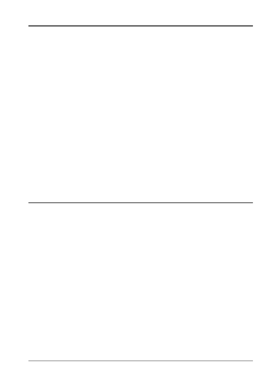
Problem of reference
1.1 Geometry
Average radius: R
O
=
1m
Thickness
: H
= 0.02 m
Height
: L
= 4 m
Internal radius: R
I
=
R
O
H/2
1.2
Material properties
Young modulus
: E = 2.1 X 10
11
AP
Poisson's ratio:
= 0.3
1.3
Boundary conditions and loadings
·
Axial displacement no one at the low end (U = 0) + conditions of symmetry
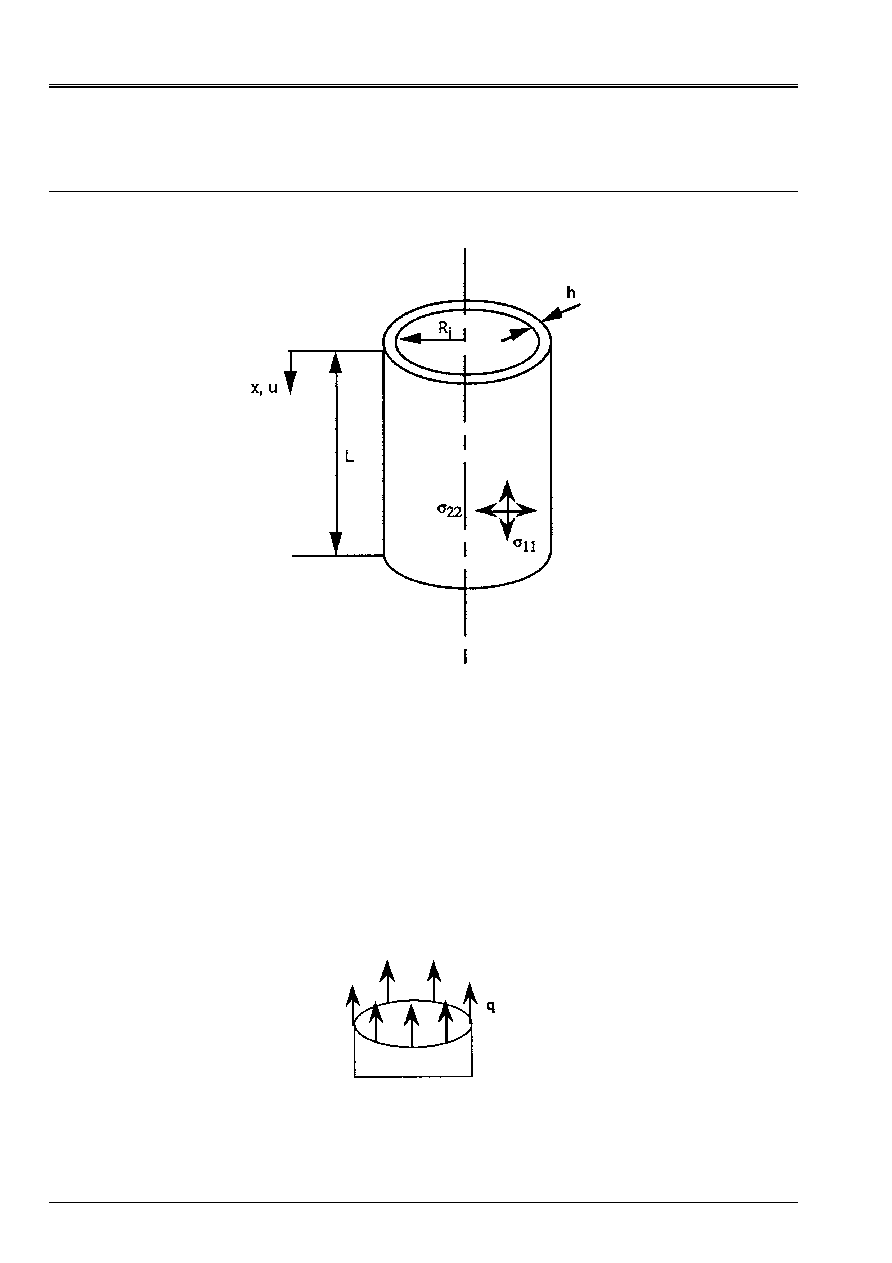
·
Uniform axial loading per unit of length Q = 10000 NR/m, applied at the high end
1.4 Conditions
initial
Without object for the static analysis.
Code_Aster
®
Version
6.5
Titrate:
SSLS07 - Thin cylinder under uniform axial loading
Date
:
01/10/03
Author (S):
X. DESROCHES
Key
:
V3.03.007-A
Page:
3/8
Manual of Validation
V3.03 booklet: Linear statics of the plates and hulls
HT-66/03/008/A
2
Reference solution
2.1
Method of calculation used for the reference solution
Axial stress:
H
Q
=
11
Circumferential stress:
0
22
=
Lengthening of the cylinder:
Eh
qL
U
X
=
Radial displacement:
Eh
R
Q
U
O
R
-
=
2.2
Results of reference
11
= 5 X 10
5
AP
X
U
= 9.52 X 10
6
m
R
U
= 7.14 X 10
7
m
2.3
Uncertainty on the solution
Analytical solution.
2.4 Reference
bibliographical
[1]
Guide VPCS Edition 1990 (SSLS 07/89)
[2]
R.J. ROARK and W.C. YOUNG: Formulated for stress and strain, 5
ème
edition, New York,
Mc Graw-Hill, 1975
Code_Aster
®
Version
6.5
Titrate:
SSLS07 - Thin cylinder under uniform axial loading
Date
:
01/10/03
Author (S):
X. DESROCHES
Key
:
V3.03.007-A
Page:
4/8
Manual of Validation
V3.03 booklet: Linear statics of the plates and hulls
HT-66/03/008/A
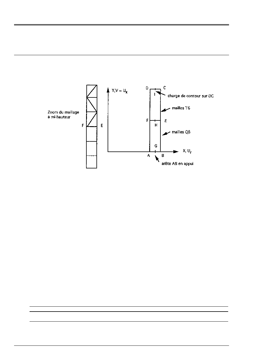
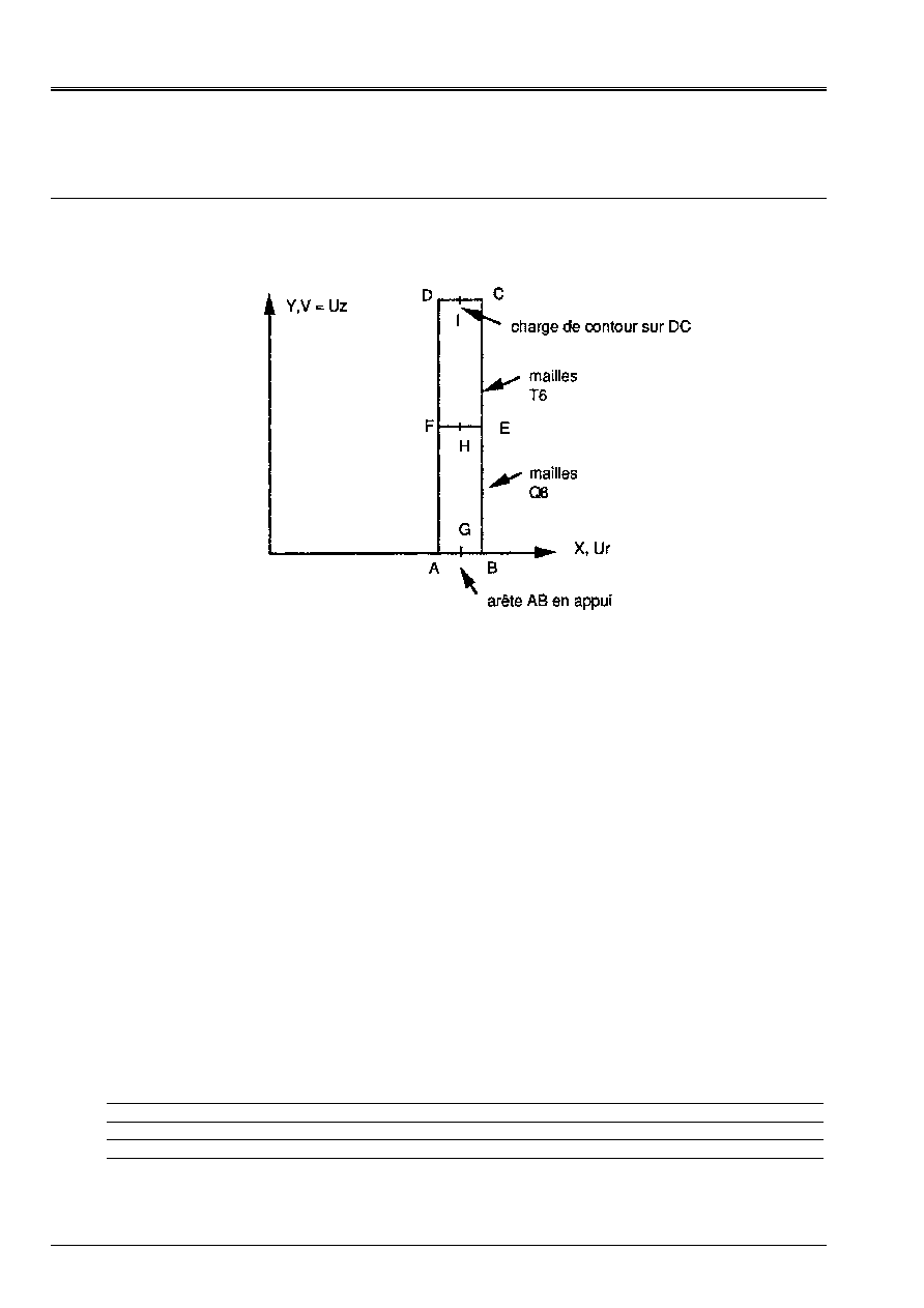
3 Modeling
With
3.1
Characteristics of modeling
AXIS, T6 meshs and Q8
Position of the points:
·
E, F with middle height
·
G, H, I remote R
O
axis
Cutting:
100 elements according to the height
1 element in the thickness
Limiting conditions: DY = 0
on AB
Loading:
Force distributed = 500 000
on CD
Name of the nodes:
Not A = N1
Not C = N452
Not E = N201
Not G = N51
Not I = N503
Not B = N101
Not D = N504
Not F = N203
Not H = N202
3.2
Characteristics of the mesh
A number of nodes: 553
A number of meshs and types: 50 QUAD8, 100 TRIA6, 204 SEG3
3.3 Functionalities
tested
Controls
“MECHANICAL” AFFE_MODELE “AXIS”
ALL
AFFE_CHAR_MECA DDL_IMPO
FORCE_CONTOUR
GROUP_NO
GROUP_MA
CALC_CHAM_ELEM OPTION
“SIGM_ELNO_DEPL”

Code_Aster
®
Version
6.5
Titrate:
SSLS07 - Thin cylinder under uniform axial loading
Date
:
01/10/03
Author (S):
X. DESROCHES
Key
:
V3.03.007-A
Page:
5/8
Manual of Validation
V3.03 booklet: Linear statics of the plates and hulls
HT-66/03/008/A
4
Results of modeling A
4.1 Values
tested
Standard localization
of
value Reference Aster
% difference
Points G, H, I
U
R
(m)
7.14 10
7
7.14 10
7
0.
Points C, D, I
U
X
(m)
9.52 10
6
9.52 10
6
0.
Points A, B, C, D, E,
F, G, H, I
22
(AP)
0.
10
6
-
Points A, B, C, D, E,
F, G, H, I
11
(AP)
5. 10
5
5.00 10
5
0.
4.2 Notice
The Fy value provided corresponds to the pressure p = Q/h.
Code_Aster
®
Version
6.5
Titrate:
SSLS07 - Thin cylinder under uniform axial loading
Date
:
01/10/03
Author (S):
X. DESROCHES
Key
:
V3.03.007-A
Page:
6/8
Manual of Validation
V3.03 booklet: Linear statics of the plates and hulls
HT-66/03/008/A
5 Modeling
B
5.1
Characteristics of modeling
AXIS, T6 meshs and Q8
Position of the points:
·
E, F with middle height
·
G, H, I remote R
O
axis
Cutting: 100 elements according to the height
1 element in the thickness
The load is broken up in the following way:
·
charge q1 varying linearly of 0 in D with 10000 NR/m out of C field of displacements
U1
·
charge q2 varying linearly of 10000 NR/m in D with 0 out of C field of displacements
U2
The results are given separately for each field
U1
and
U2
.
Name of the nodes:
Not A = N1
Not C = N452
Not E = N201
Not G = N51
Not I = N503
Not B = N101
Not D = N504
Not F = N203
Not H = N202
5.2
Characteristics of the mesh
A number of nodes: 557
A number of meshs and types: 50 QUAD8, 100 TRIA6, 204 SEG3
5.3 Functionalities
tested
Controls
“MECHANICAL” AFFE_MODELE “AXIS”
ALL
AFFE_CHAR_MECA_F FORCE_CONTOUR
GROUP_MA
AFFE_CHAR_MECA DDL_IMPO
GROUP_NO
CALC_CHAM_ELEM OPTION
“SIGM_ELNO_DEPL”

Code_Aster
®
Version
6.5
Titrate:
SSLS07 - Thin cylinder under uniform axial loading
Date
:
01/10/03
Author (S):
X. DESROCHES
Key
:
V3.03.007-A
Page:
7/8
Manual of Validation
V3.03 booklet: Linear statics of the plates and hulls
HT-66/03/008/A
6
Results of modeling B
6.1 Values
tested
Fields Standard Localization
of
value
Reference
Aster
% difference
U1
Not G (N51)
Not H (N202)
Not I (N503)
U
R
(m)
3,583. 10
7
3,583. 10
7
1,012. 10
6
3,5833. 10
7
3,5833. 10
7
1,0116. 10
7
0,009
0,009
0,036
Not C (N452)
Not D (N504)
Not I (N503)
U
X
(m)
4,896. 10
6
4,658. 10
6
4,777. 10
6
4,8963. 10
6
4,6583. 10
6
4,7774. 10
6
0,007
0,006
0,009
U2
Not G
Not H
Not I
U
R
(m)
3,559. 10
7
3,559. 10
7
2,973. 10
7
3,5595. 10
7
3,5595. 10
7
2,9735. 10
7
0,015
0,015
0,017
Not C (N452)
Not D (N504)
Not I (N503)
4,627. 10
6
4,865. 10
6
4,746. 10
6
4,6275. 10
6
4,8655. 10
6
4,7464. 10
6
0,001
0,011
0,008

Code_Aster
®
Version
6.5
Titrate:
SSLS07 - Thin cylinder under uniform axial loading
Date
:
01/10/03
Author (S):
X. DESROCHES
Key
:
V3.03.007-A
Page:
8/8
Manual of Validation
V3.03 booklet: Linear statics of the plates and hulls
HT-66/03/008/A
7
Summary of the results
Key word FORCE_CONTOUR used starting from 2 controls AFFE_CHAR_MECA and
AFFE_CHAR_MECA_F provides right results.