
Code_Aster
®
Version
4.0
Titrate:
SSLS100 Plates circular embedded subjected to a pressure
Date:
22/12/98
Author (S):
P. MASSIN, D. BUI, A. LAULUSA
Key
:
V3.03.100-C AP
Ge:
1/24
Manual of Validation
V3.03 booklet: Linear statics of the hulls and the plates
HI-75/01/010/A
Organization (S):
EDF/IMA/MN, SAMTECH
Manual of Validation
V3.03 booklet: Linear statics of the hulls and the plates
Document: V3.03.100
SSLS100 - Plate circular embedded subjected
with a uniform pressure
Summary:
This problem allows a comparison between the solutions obtained and various elements of plate in elasticity
linear:
·
models of Coils-Kirchhoff (plate known as thin):
-
triangular surface mesh (
TRIA3
)
DKT
,
-
quadrangular surface mesh (
QUAD4
)
DKQ
,
-
linear mesh (
SEG3
)
COQUE_AXIS
,
·
models of Mindlin-Reissner (plate known as thick):
-
triangular surface mesh (
TRIA3
)
DST
,
-
quadrangular surface mesh (
QUAD4
)
DSQ
,
-
linear mesh (
SEG3
)
COQUE_AXIS
,
·
models of hulls thick:
COQUE_3D
(
QUAD9
and
TRIA7
).
The same reference solution is treated with three forms of loadings: pressure, gravity and
force-hull. The sizes observed are: displacements (translation/rotation), deformations and efforts
generalized.
Modelings C and D were removed: resorption of modeling
COQU_CYL
.
Code_Aster
®
Version
4.0
Titrate:
SSLS100 Plates circular embedded subjected to a pressure
Date:
22/12/98
Author (S):
P. MASSIN, D. BUI, A. LAULUSA
Key
:
V3.03.100-C AP
Ge:
2/24
Manual of Validation
V3.03 booklet: Linear statics of the hulls and the plates
HI-75/01/010/A
1
Problem of reference
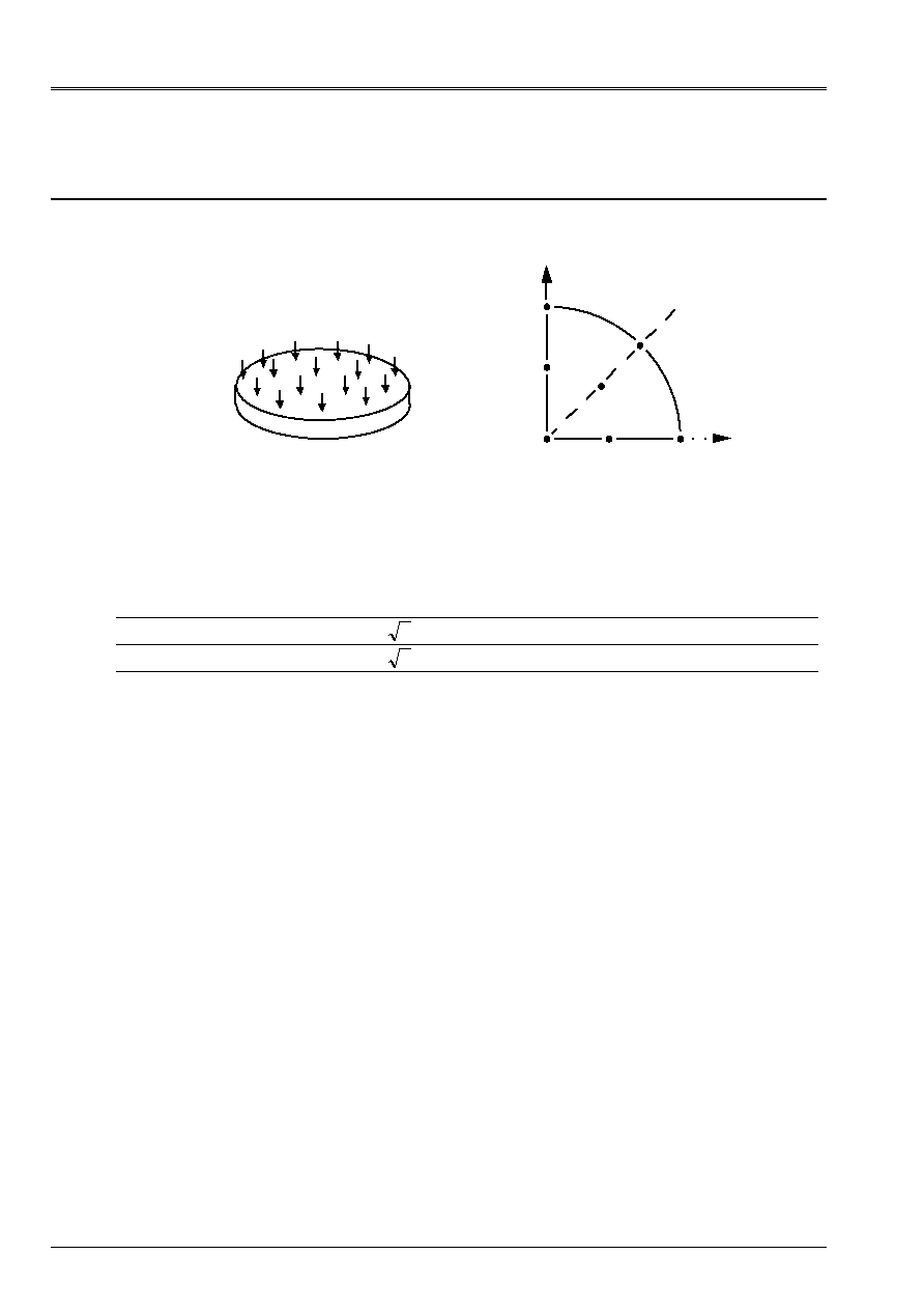
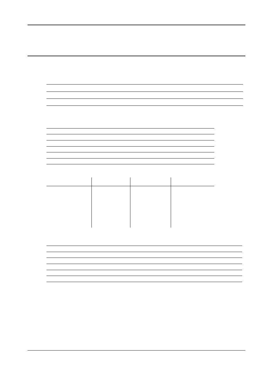
1.1 Geometry
With
B
C
O
D
E
F
y
X
1/4 of plate
Radius
R = 1 m
Thickness
T = 0.1 m
Co-ordinates of the points:
0 A B C D E F
X 0.
1.
2 2
/
0. 0.5
0.
0.4
y 0.
0.
2 2
/
1. 0.
0.5
0.4
Z 0
0.
0.
0.
0.
0.
0.
1.2
Material properties
E = 1 AP
= 0.3
= 1 kg/m
3
1.3
Boundary conditions and loadings
Embedding on the edge of the plate:
in all the points P such as COp = R: U = v = W = 0,
X
=
y
=
Z
= 0.
FORCE_COQUE
Uniform pressure
P = 1 NR/m
2
FORCE_COQUE
Charge distributed normal
F3 = 1 NR/m
2
GRAVITY
G = 10 m/s
2
according to Z
from where
FZ =
WP = 1 NR/m
2
These three loadings lead to the same solution.

Code_Aster
®
Version
4.0
Titrate:
SSLS100 Plates circular embedded subjected to a pressure
Date:
22/12/98
Author (S):
P. MASSIN, D. BUI, A. LAULUSA
Key
:
V3.03.100-C AP
Ge:
3/24
Manual of Validation
V3.03 booklet: Linear statics of the hulls and the plates
HI-75/01/010/A
2
Reference solution
2.1
Method of calculation used for the reference solution
Two reference solutions are usable, for the calculation of the deformation:
·
the theory of LOVE-KIRCHHOFF, usually used for the plates known as “thin”, that
one will retain for modelings A, B, C, D, E and I,
·
the theory of MINDLIN-REISSNER, including the effects of shearing for the plates known as
“thick”, that one will retain for modelings F, G, H and J.
In any distant point of R of the center of the plate (R R), the arrow is expressed:
()
(
)
W R
P R
D
R
R
R
R
D
E T
T
R
= -
-
-
+
=
-
=
=
-
-
4
2
2
2
2
3
2
2
64
1
1
12 1
0
16
5
1
1
.
with
with
(KIRCHHOFF COILS) or
(REISSNER)
For the calculation of the moments the two theories lead to the same expressions:
()
(
)
(
)
()
(
)
(
)
M
R
P R
R
R
M
R
P R
R
R
rr
=
+ - +
=
+
- +
2
2
2
2
16
3
1
16
1 3
1
In the center of the plate:
()
()
(
)
()
()
(
)
W
P R
D
W
P R
D
M
M
P R
rr
0
64
0
64
1
0
0
16 1
4
4
2
= -
= -
+
=
= -
+
-
(
)
(
)
COIL KIRCHHOFF or
REISSNER
Note:
Code_Aster calculates the moments with the nodes of each finite element in the reference mark of
reference defined by the external normal and the reference axes defined on the hull (see
AFFE_CARA_ELEM
[U4.24.01]).
The value of the moment
M
xx
(or
M
yy
) in a node pertaining to several finite elements can
to be regarded as being the average of the computed values on the elements which have this node
jointly. This average can be obtained by the procedure
POST_RELEVE
[U4.74.03].
For each node, one a:
(
)
(
)
M
M
M
M
Sm
rr
xx
yy
+
=
+
=
(
)
for the point O
for the points A and D
and
for the points C and E
and
for the points B and F
M
M
M
M
M
M
M
M
M
M
M
M
M
M
M
M
xx
yy
rr
xx
rr
yy
xx
yy
rr
xx
yy
rr
=
=
=
=
=
=
=
=
=
+
/2
2.2
Results of reference
Arrow and moments at the points O, A, B, C, D, E, F. Extraction of the average values of the components
M
M
xx
yy
and
field
“EFGE_ELNO_DEPL”
.
2.3
Uncertainty on the solution
Analytical solution.
2.4 References
bibliographical
[1]
TIMOSHENKO and WOINOWSKY-KRIEGER. Plates and hulls. Béranger edition, (1961).
[2]
BATOZ and DHATT. Modeling of the structures by finite elements. Hulls. Presses
Univ. Laval, 1992.
Code_Aster
®
Version
4.0
Titrate:
SSLS100 Plates circular embedded subjected to a pressure
Date:
22/12/98
Author (S):
P. MASSIN, D. BUI, A. LAULUSA
Key
:
V3.03.100-C AP
Ge:
4/24
Manual of Validation
V3.03 booklet: Linear statics of the hulls and the plates
HI-75/01/010/A
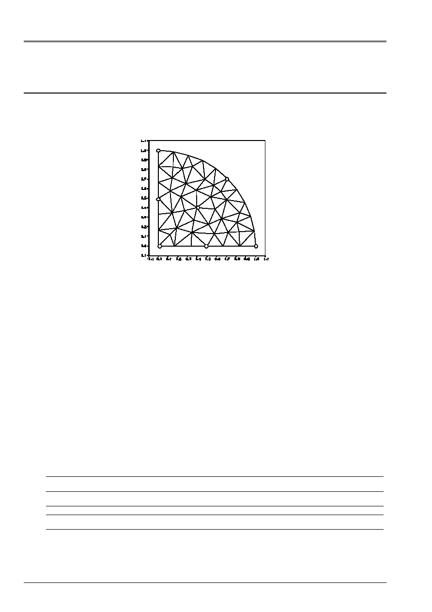
3 Modeling
With
3.1
Characteristics of modeling
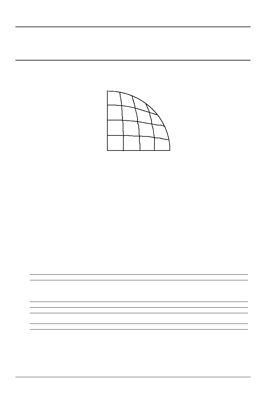
Element of hull DKT (modeling of a quarter of plate)
O
With
B
C
E
D
F
Limiting conditions:
DDL_IMPO
in all the nodes of the arc ABC
(GROUP_NO: ABC DX: 0., DY: 0., DZ: 0.)
DRX:0., DRY:0., DRZ:0.)
in all the nodes of segment] OA [
(GROUP_NO: OA DY: 0., DRX:0., DRZ:0.)
in all the nodes of segment] OC [
(GROUP_NO: OC DX: 0., DRY:0., DRZ:0.)
with the node O
(GROUP_NO: O DX: 0., DY: 0., DRX:0., DRY:0., DRZ:0.)
Not O
meshs: M30, M33
Not A
meshs: M76
Not B
meshs: M39, M40, M51
Not C
meshs: M1
Not D
meshs: M55, M56, M65
Not E
meshs: M8, M17, M18
Not F
meshs: M34, M35, M37, M41, M46, M47, M48
3.2
Characteristics of the mesh
A number of nodes: 50
A number of meshs and types: 76 TRIA3
3.3 Functionalities
tested
Controls
Keys
AFFE_CARA_ELEM HULL
THICK
ANGL_REP
[U4.24.01]
AFFE_CHAR_MECA DDL_IMPO
FORCE_COQUE
GROUP_NO
NEAR
[U4.25.01]
“MECHANICAL” AFFE_MODELE “DKT”
ALL
[U4.22.01]
CALC_CHAM_ELEM “EFGE_ELNO_DEPL”
“SIGM_ELNO_DEPL”
[U4.61.01]
POST_RELEVE ACTION
OPERATION
“EXTRACTION”
[U4.74.03]

Code_Aster
®
Version
4.0
Titrate:
SSLS100 Plates circular embedded subjected to a pressure
Date:
22/12/98
Author (S):
P. MASSIN, D. BUI, A. LAULUSA
Key
:
V3.03.100-C AP
Ge:
5/24
Manual of Validation
V3.03 booklet: Linear statics of the hulls and the plates
HI-75/01/010/A
4
Results of modeling A
4.1 Values
tested
Not Reference
Coil-Kirchhoff
Aster %
difference
tolerance
O
()
W R
170.6251 169.32
0.76
rel 1.10
2
D
()
W R
95.9766 95.76
0.23 rel 0.5 10
2
E
()
W R
95.9766 95.73
0.25 rel 0.5 10
2
F
()
W R
78.897 78.64
0.32 rel 0.5 10
2
Reference
Not
M
rr
M
Sm/2
O
0.08125 0.08125 0.08125
With
+0.125 +0.0375 +0.08125
B
+0.125 +0.0375 +0.08125
C
+0.125 +0.0375 +0.08125
D
0.02969 0.05156 0.04062
E
0.02969 0.05156 0.04062
F
0.01525 0.04325 0.02925
Aster
Not
M
xx
M
yy
Sm/2
O
0.08031 0.08033 0.08032
With
+0.1260 +0.0378 +0.0819
B
+0.08487 +0.08507 +0.08497
C
+0.03778 +0.1259 +0.08184
D
0.03166 0.05328 0.04227
E
0.05330 0.03164 0.04247
F
0.02958 0.02994 0.02974
% difference (with eps 10
- 14
and % difference on the absolute values)
Not
M
xx
M
yy
Sm/2
Relative tolerance
O
1.15 1.14 1.15
1.5
With
+0.81 +0.81 +0.81
1.
B
+4.46 +4.71 +4.58
5.
C
+0.75 +0.75 +0.75
1.
D
+6.65 +3.34 +4.55
7./3.5
E
+3.38 +6.58 +4.55
3.5/7.
F
+1.14 +2.35 +1.71
1.5
4.2 Parameters
of execution
Version: 4.00.02
Machine: CRAY C90
System:
UNICOS 8.0
Overall dimension memory:
16 MW
Time CPU To use:
5.7 seconds
Code_Aster
®
Version
4.0
Titrate:
SSLS100 Plates circular embedded subjected to a pressure
Date:
22/12/98
Author (S):
P. MASSIN, D. BUI, A. LAULUSA
Key
:
V3.03.100-C AP
Ge:
6/24
Manual of Validation
V3.03 booklet: Linear statics of the hulls and the plates
HI-75/01/010/A
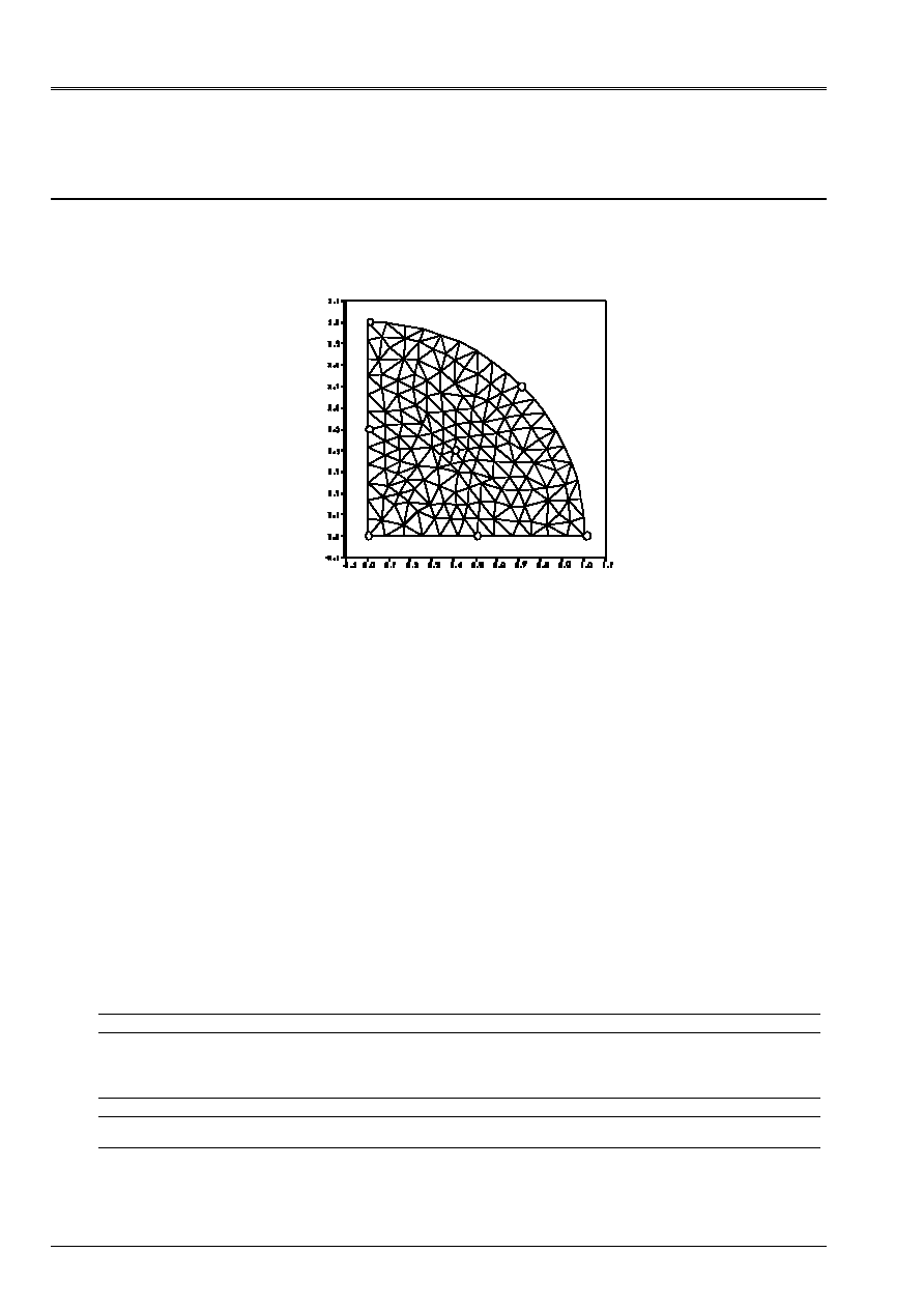
5 Modeling
B
5.1
Characteristics of modeling
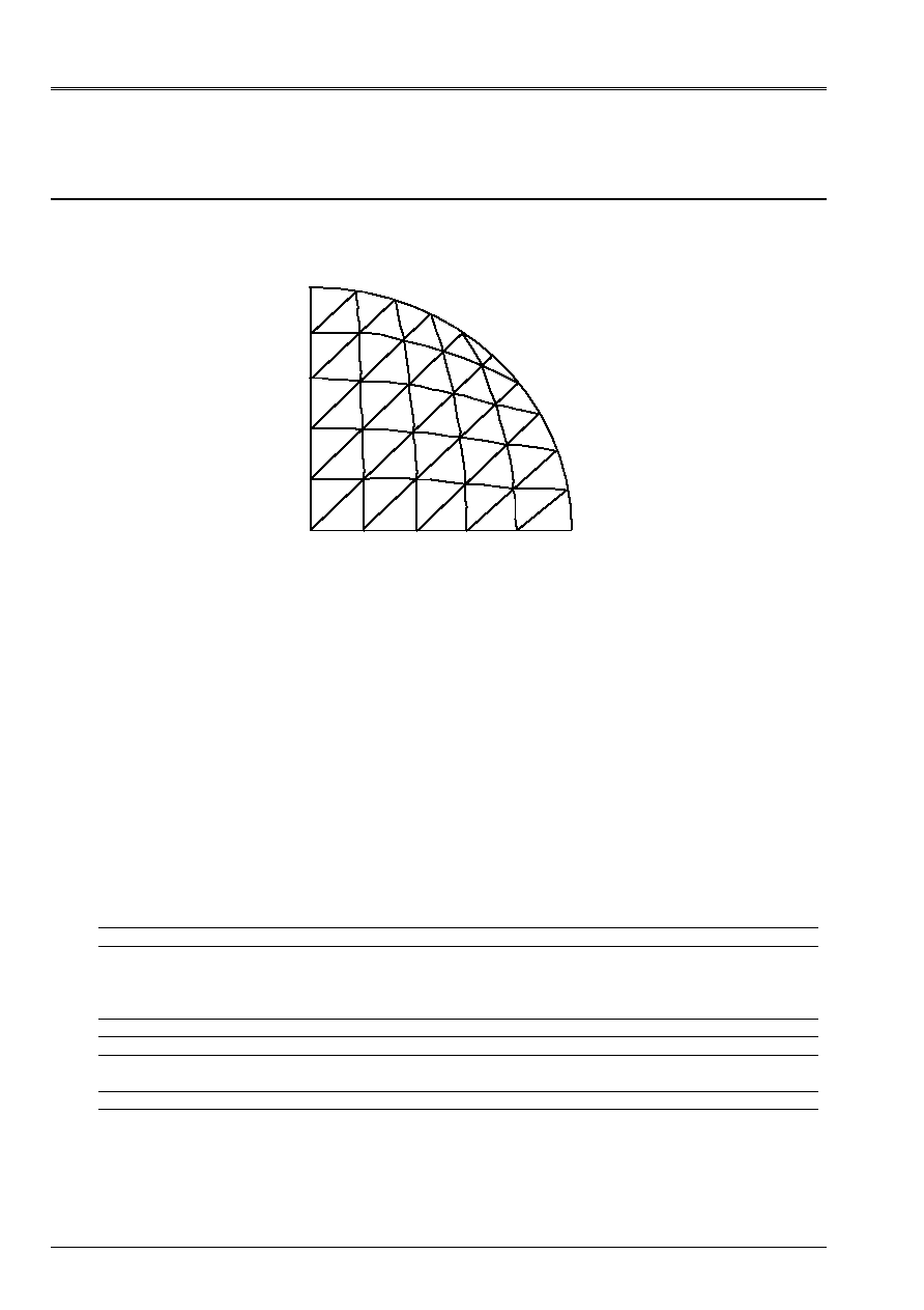
Element of hull
DKT (
modeling of a quarter of plate)
C
O
With
D
B
E
F
Limiting conditions:
DDL_IMPO
in all the nodes of the arc ABC
(GROUP_NO: ABC DX: 0., DY: 0., DZ: 0.)
DRX:0., DRY:0., DRZ:0.)
in all the nodes of segment] OA [
(GROUP_NO: OA DY: 0., DRX:0., DRZ:0.)
in all the nodes of segment] OC [
(GROUP_NO: OC DX: 0., DRY:0., DRZ:0.)
with the node O
(GROUP_NO: O DX: 0., DY: 0., DRX:0., DRY:0., DRZ:0.)
Not O
meshs: M1 m2
Not A
meshs: M248 M255
Not B
meshs: M292 M293 M296
Not C
meshs: M74 M75
Not D
meshs: M76 M108 M109
Not E
meshs: M34 M40 M41
Not F
meshs: M122 M123 M124 M148 M152 M153
5.2
Characteristics of the mesh
A number of nodes: 170
A number of meshs and types: 296 TRIA3
5.3 Functionalities
tested
Controls
Keys
AFFE_CARA_ELEM HULL
[U4.24.01]
AFFE_CHAR_MECA DDL_IMPO
FORCE_COQUE
GROUP_NO
NEAR
F3
[U4.25.01]
GRAVITY
“MECHANICAL” AFFE_MODELE “DKT”
ALL
[U4.22.01]
CALC_CHAM_ELEM “EFGE_ELNO_DEPL”
“SIGM_ELNO_DEPL”
[U4.61.01]
POST_RELEVE ACTION
OPERATION
“EXTRACTION”
[U4.74.03]

Code_Aster
®
Version
4.0
Titrate:
SSLS100 Plates circular embedded subjected to a pressure
Date:
22/12/98
Author (S):
P. MASSIN, D. BUI, A. LAULUSA
Key
:
V3.03.100-C AP
Ge:
7/24
Manual of Validation
V3.03 booklet: Linear statics of the hulls and the plates
HI-75/01/010/A
6
Results of modeling B
6.1 Values
tested
Not Reference
Coil-Kirchhoff
Aster %
difference
tolerance
O
()
W R
170.6251 170.8384 0.12 rel 0.5 10
2
D
()
W R
95.9766 96.1477 0.18
rel 0.5 10
2
E
()
W R
95.9766 96.2078 0.24
rel 0.5 10
2
F
()
W R
78.897 79.072 0.22
rel 0.5 10
2
Reference
Not
M
rr
M
Sm/2
O
0.08125 0.08125 0.08125
With
+0.125 +0.0375 +0.08125
B
+0.125 +0.0375 +0.08125
C
+0.125 +0.0375 +0.08125
D
0.02969 0.05156 0.04062
E
0.02969 0.05156 0.04062
F
0.01525 0.04325 0.02925
Aster
Not
M
xx
M
yy
Sm/2
O
0.08151 0.08131 0.08141
With
0.1282 0.04083 0.08451
B
0.08340 0.08340 0.08340
C
0.04085 0.12836 0.08460
D
0.03037 0.05249 0.04143
E
0.05259 0.03043 0.04151
F
0.02981 0.02988 0.02985
% difference (with eps 10
- 14
and % difference on the absolute values)
Not
M
xx
M
yy
Sm/2
Relative tolerance
O
0.33 0.07 0.19
0.5
With
2.62 8.88 4.02
3./9.
B
2.64 2.64 2.64
3.
C
8.95 2.69 4.13
9./3.
D
2.29 1.81 1.99
2.5
E
2.01 2.49 2.19
2.5
F
1.92 2.18 2.05
2.5
6.2 Parameters
of execution
Version: 4.00.02
Machine: CRAY C90
System:
UNICOS 8.0
Overall dimension memory:
16 megawords
Time CPU To use:
9.5 seconds
Code_Aster
®
Version
4.0
Titrate:
SSLS100 Plates circular embedded subjected to a pressure
Date:
22/12/98
Author (S):
P. MASSIN, D. BUI, A. LAULUSA
Key
:
V3.03.100-C AP
Ge:
8/24
Manual of Validation
V3.03 booklet: Linear statics of the hulls and the plates
HI-75/01/010/A
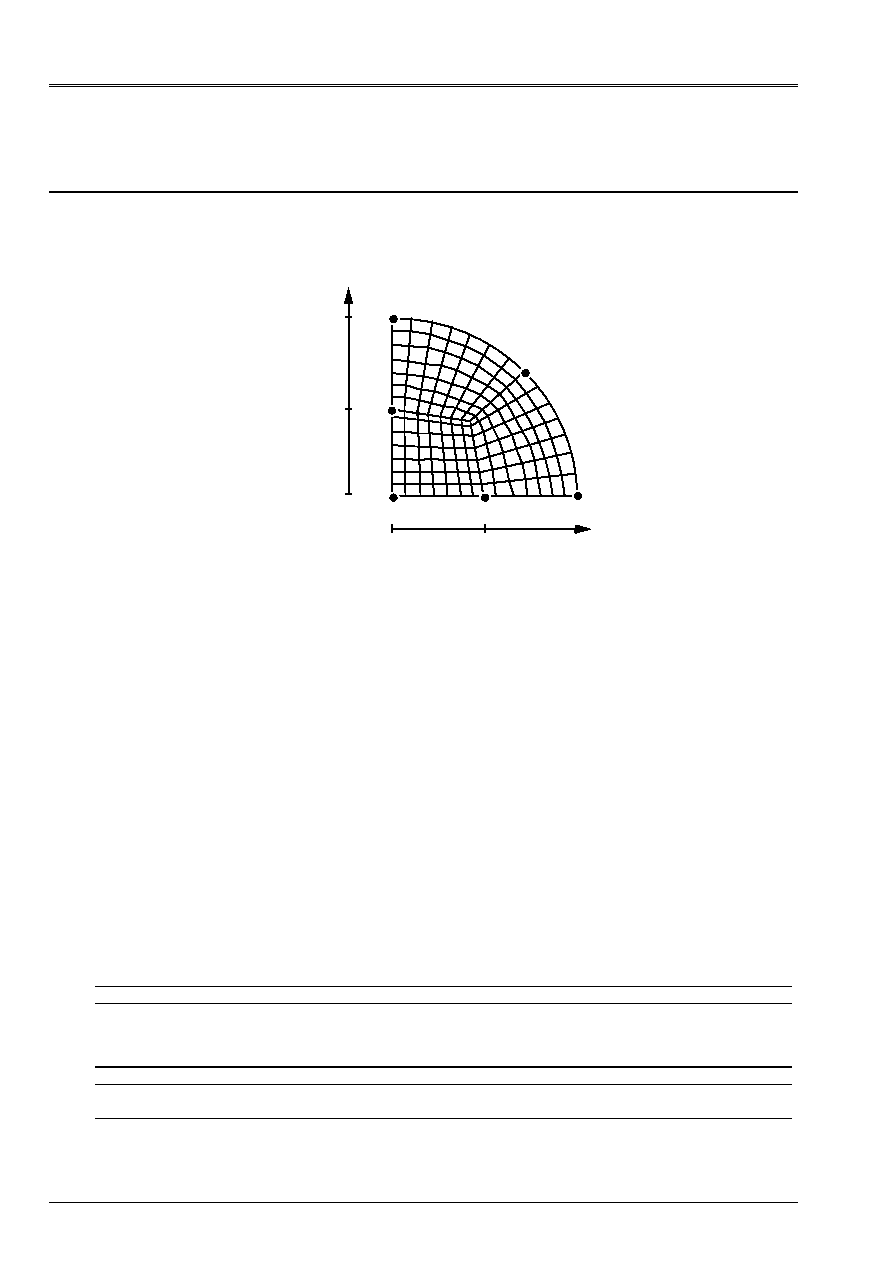
7 Modeling
E
7.1
Characteristics of modeling
Element of hull
DKQ
(modeling of a quarter of plate)
C
B
With
D
E
0.0
0.5
1.0
0.0
1.0
0.5
O
Limiting conditions:
DDL_IMPO
in all the nodes of the arc ABC
(GROUP_NO: ABC DX: 0., DY: 0., DZ: 0.)
DRX:0., DRY:0., DRZ:0.)
in all the nodes of segment] OA [
(GROUP_NO: OA DY: 0., DRX:0., DRZ:0.)
in all the nodes of segment] OC [
(GROUP_NO: OC DX: 0., DRY:0., DRZ:0.)
with the node O
(GROUP_NO: O DX: 0., DY: 0., DRX:0., DRY:0., DRZ:0.)
Not O
meshs: M1
Not A
meshs: M147
Not B
meshs: M98 M111
Not C
meshs: M14
Not D
meshs: M85 M99
Not E
meshs: M7 M8
Not F
meshs: M91 M92 M105
7.2
Characteristics of the mesh
A number of nodes: 169
A number of meshs and types: 147 QUAD4
7.3 Functionalities
tested
Controls
Keys
AFFE_CARA_ELEM HULL
[U4.24.01]
AFFE_CHAR_MECA DDL_IMPO
FORCE_COQUE
GROUP_NO
NEAR
F3
[U4.25.01]
GRAVITY
“MECHANICAL” AFFE_MODELE “DKT”
ALL
[U4.22.01]
CALC_CHAM_ELEM “EFGE_ELNO_DEPL”
“SIGM_ELNO_DEPL”
[U4.61.01]
POST_RELEVE ACTION
OPERATION
“EXTRACTION”
[U4.74.03]

Code_Aster
®
Version
4.0
Titrate:
SSLS100 Plates circular embedded subjected to a pressure
Date:
22/12/98
Author (S):
P. MASSIN, D. BUI, A. LAULUSA
Key
:
V3.03.100-C AP
Ge:
9/24
Manual of Validation
V3.03 booklet: Linear statics of the hulls and the plates
HI-75/01/010/A
8
Results of modeling E
8.1 Values
tested
Not Reference
Coil-Kirchhoff
Aster %
difference
tolerance
O
()
W R
170.6251 171.00
0.22 rel 0.5 10
2
D
()
W R
95.9766 96.198 0.23
rel 0.5 10
2
E
()
W R
95.9766 96.198 0.23
rel 0.5 10
2
F
()
W R
78.897 79.06 0.20
rel 0.5 10
2
Reference
Not
M
rr
M
Sm/2
O
0.08125 0.08125
0.08125
With
+0.125 +0.0375
+0.08125
B
+0.125 +0.0375
+0.08125
C
+0.125 +0.0375
+0.08125
D
0.02969 0.05156
0.04062
E
0.02969 0.05156
0.04062
F
0.01525 0.04325
0.02925
Aster
Not
M
xx
M
yy
Sm/2
O
0.08162 0.08162 0.08162
With
0.1256 0.03768 0.08164
B
0.08141 0.08140 0.08141
C
0.03767 0.12557 0.08162
D
0.03030 0.05314 0.04172
E
0.05314 0.03030 0.04172
F
0.02903 0.02901 0.02902
% difference (with eps 10
14
and % difference on the absolute values)
Not
M
xx
M
yy
Sm/2
Relative tolerance
O
0.46 0.46 0.46
0.5
With
0.49 0.49 0.49
0.5
B
0.2.0.2.0.2
0.5
C
0.45 0.45 0.45
0.5
D
2.06 3.07 2.71
2.5/3.5
E
3.07 2.06 2.71
3.5/2.5
F
0.73 0.83 0.79
1
8.2 Parameters
of execution
Version: 4.00.02
Machine: CRAY C90
System:
UNICOS 8.0
Overall dimension memory:
16 megawords
Time CPU To use:
8.4 seconds

Code_Aster
®
Version
4.0
Titrate:
SSLS100 Plates circular embedded subjected to a pressure
Date:
22/12/98
Author (S):
P. MASSIN, D. BUI, A. LAULUSA
Key
:
V3.03.100-C AP
Ge:
10/24
Manual of Validation
V3.03 booklet: Linear statics of the hulls and the plates
HI-75/01/010/A
9 Modeling
F
9.1
Characteristics of modeling
Element of hull
DST
(modeling of a quarter of plate)
C
O
With
D
B
E
F
Limiting conditions:
DDL_IMPO
in all the nodes of the arc ABC
(GROUP_NO: AB DX: 0., DY: 0., DZ: 0.)
DRX:0., DRY:0., DRZ:0.)
in all the nodes of segment] OA [
(GROUP_NO: OA DY: 0., DRX:0., DRZ:0.)
in all the nodes of segment] OC [
(GROUP_NO: OC DX: 0., DRY:0., DRZ:0.)
with the node O
(GROUP_NO: O DX: 0., DY: 0., DRX:0., DRY:0., DRZ:0.)
Not O
meshs: M1 m2
Not A
meshs: M248 M255
Not B
meshs: M292 M293 M296
Not C
meshs: M74 M75
Not D
meshs: M76 M108 M109
Not E
meshs: M34 M40 M41
Not F
meshs: M122 M123 M124 M148 M152 M153
9.2
Characteristics of the mesh
A number of nodes: 170
A number of meshs and types: 296 TRIA3
9.3 Functionalities
tested
Controls
Keys
AFFE_CARA_ELEM HULL
[U4.24.01]
AFFE_CHAR_MECA DDL_IMPO
FORCE_COQUE
GROUP_NO
NEAR
F3
[U4.25.01]
GRAVITY
“MECHANICAL” AFFE_MODELE “DST”
ALL
[U4.22.01]
CALC_CHAM_ELEM “EFGE_ELNO_DEPL”
“SIGM_ELNO_DEPL”
[U4.61.01]
POST_RELEVE ACTION
OPERATION
“EXTRACTION”
[U4.74.03]

Code_Aster
®
Version
4.0
Titrate:
SSLS100 Plates circular embedded subjected to a pressure
Date:
22/12/98
Author (S):
P. MASSIN, D. BUI, A. LAULUSA
Key
:
V3.03.100-C AP
Ge:
11/24
Manual of Validation
V3.03 booklet: Linear statics of the hulls and the plates
HI-75/01/010/A
10 Results of modeling F
10.1 Values
tested
Not Reference
Reissner
Aster %
difference tolerance
O
()
W R
178.419 179.743 +0.74 rel 1.0 10
2
D
()
W R
101.82 102.60 +0.77 rel 1.0 10
2
E
()
W R
101.82 102.67 +0.84 rel 1.0 10
2
F
()
W R
84.198 84.83 +0.75 rel 1.0 10
2
Reference
Not
M
rr
M
Sm/2
O
0.08125 0.08125 0.08125
With
+0.125 +0.0375 +0.08125
B
+0.125 +0.0375 +0.08125
C
+0.125 +0.0375 +0.08125
D
0.02969 0.05156 0.04062
E
0.02969 0.05156 0.04062
F
0.01525 0.04325 0.02925
Aster
Not
M
xx
M
yy
Sm/2
O
0.08216 0.08204 0.08210
With
+0.12515 +0.04591 +0.08553
B
+0.08289 +0.08289 +0.08289
C
+0.04594 +0.12524 +0.08559
D
0.03108 0.05184 0.04146
E
0.05195 0.03116 0.04155
F
0.02956 0.02963 0.02960
% difference (with eps 10
14
and % difference on the absolute values)
Not
M
xx
M
yy
Sm/2
Relative tolerance
O
+1.12 0.97 +1.04
1.5/1.
With
+0.12 +22.44 +5.26
0.5/23.
B
+2.02 +2.02 +2.02
2.5
C
+22.52 +0.19 +5.34
23./0.5
D
+4.67 +0.54 +2.07
5./1.
E
+0.76 +4.94 +2.29
1./5.
F
+1.07 +1.33 +1.19
1.5
10.2 Contents of the file results
Values at the points of observation of displacements and moments realized.
10.3 Parameters
of execution
Version: 4.00.02
Machine: CRAY C90
System:
UNICOS 8.0
Overall dimension memory:
16 megawords
Time CPU To use:
9.2 seconds

Code_Aster
®
Version
4.0
Titrate:
SSLS100 Plates circular embedded subjected to a pressure
Date:
22/12/98
Author (S):
P. MASSIN, D. BUI, A. LAULUSA
Key
:
V3.03.100-C AP
Ge:
12/24
Manual of Validation
V3.03 booklet: Linear statics of the hulls and the plates
HI-75/01/010/A
11 Modeling
G
11.1 Characteristics of modeling
Element of hull
DSQ
(modeling of a quarter of plate)
C
B
With
D
E
0.0
0.5
1.0
0.0
1.0
0.5
O
Limiting conditions:
DDL_IMPO
in all the nodes of the arc ABC
(GROUP_NO: ABC DX: 0., DY: 0., DZ: 0.)
DRX:0., DRY:0., DRZ:0.)
in all the nodes of segment] OA [
(GROUP_NO: OA DY: 0., DRX:0., DRZ:0.)
in all the nodes of segment] OC [
(GROUP_NO: OC DX: 0., DRY:0., DRZ:0.)
with the node O
(GROUP_NO: O DX: 0., DY: 0., DRX:0., DRY:0., DRZ:0.)
Not O
meshs: M1
Not A
meshs: M147
Not B
meshs: M98 M111
Not C
meshs: M14
Not D
meshs: M85 M99
Not E
meshs: M7 M8
Not F
meshs: M91 M92 M105
11.2 Characteristics of the mesh
A number of nodes: 169
A number of meshs and types: 147 QUAD4
11.3 Functionalities
tested
Controls
Keys
AFFE_CARA_ELEM HULL
[U4.24.01]
AFFE_CHAR_MECA DDL_IMPO
FORCE_COQUE
GROUP_NO
NEAR
F3
[U4.25.01]
GRAVITY
“MECHANICAL” AFFE_MODELE “DST”
ALL
[U4.22.01]
CALC_CHAM_ELEM “EFGE_ELNO_DEPL”
“SIGM_ELNO_DEPL”
[U4.61.01]
POST_RELEVE ACTION
OPERATION
“EXTRACTION”
[U4.74.03]
Code_Aster
®
Version
4.0
Titrate:
SSLS100 Plates circular embedded subjected to a pressure
Date:
22/12/98
Author (S):
P. MASSIN, D. BUI, A. LAULUSA
Key
:
V3.03.100-C AP
Ge:
13/24
Manual of Validation
V3.03 booklet: Linear statics of the hulls and the plates
HI-75/01/010/A
12 Results of modeling G
12.1 Values
tested
Not Reference
Reissner
Aster %
difference tolerance
O
()
W R
178.419 178.754 +0.19 rel 0.3 10
2
D
()
W R
101.82 102.015 +0.19 rel 0.3 10
2
E
()
W R
101.82 102.014 +0.19 rel 0.3 10
2
F
()
W R
84.198 84.318 +0.14 rel 0.3 10
2
Reference
Not
M
rr
M
Sm/2
O
0.08125 0.08125 0.08125
With
+0.125 +0.0375 +0.08125
B
+0.125 +0.0375 +0.08125
C
+0.125 +0.0375 +0.08125
D
0.02969 0.05156 0.04062
E
0.02969 0.05156 0.04062
F
0.01525 0.04325 0.02925
Aster
Not
M
xx
M
yy
Sm/2
O
0.08098 0.08098 0.08098
With
+0.12730 +0.04136 +0.08433
B
+0.08261 +0.08261 +0.08261
C
+0.04114 +0.12727 +0.08420
D
0.03029 0.05217 0.04078
E
0.05217 0.03029 0.04078
F
0.03449 0.03444 0.03447
% difference (with eps 10
- 14
and % difference on the absolute values)
Not
M
xx
M
yy
Sm/2
Relative tolerance
O
0.33 0.33 +0.33
0.5
With
+1.84 +10.31 +3.79
2./11.
B
+1.68 +1.68 +1.69
2.
C
+9.07 +1.82 +3.64
10./2.
D
+2.05 +1.19 +0.4
2.5/1.5
E
+1.19 +2.05 +0.4
1.5/2.5
F
+17.91 +17.74 +17.80
18
12.2 Contents of the file results
Values at the points of observation of displacements and moments realized.
12.3 Parameters
of execution
Version: 4.00.02
Machine: CRAY C90
System:
UNICOS 8.0
Overall dimension memory:
16 megawords
Time CPU To use:
8.6 seconds
Code_Aster
®
Version
4.0
Titrate:
SSLS100 Plates circular embedded subjected to a pressure
Date:
22/12/98
Author (S):
P. MASSIN, D. BUI, A. LAULUSA
Key
:
V3.03.100-C AP
Ge:
14/24
Manual of Validation
V3.03 booklet: Linear statics of the hulls and the plates
HI-75/01/010/A
13 Modeling
H
13.1 Characteristics of modeling
Element of hull
Q4G
(modeling of a quarter of plate)
C
B
With
D
E
0.0
0.5
1.0
0.0
1.0
0.5
O
Limiting conditions:
DDL_IMPO
in all the nodes of the arc ABC
(GROUP_NO: ABC DX: 0., DY: 0., DZ: 0.)
D DRX:0., DRY:0., DRZ:0.)
in all the nodes of segment] OA [
(GROUP_NO: OA DY: 0., DRX:0., DRZ:0.)
in all the nodes of segment] OC [
(GROUP_NO: OC DX: 0., DRY:0., DRZ:0.)
with the node O
(GROUP_NO: O DX: 0., DY: 0., DRX:0., DRY:0., DRZ:0.)
Not O
meshs: M1
Not A
meshs: M147
Not B
meshs: M98 M111
Not C
meshs: M14
Not D
meshs: M85 M99
Not E
meshs: M7 M8
Not F
meshs: M91 M92 M105
13.2 Characteristics of the mesh
A number of nodes: 169
A number of meshs and types: 147 QUAD4
13.3 Functionalities
tested
Controls
Keys
AFFE_CARA_ELEM HULL
[U4.24.01]
AFFE_CHAR_MECA DDL_IMPO
FORCE_COQUE
GROUP_NO
NEAR
F3
[U4.25.01]
GRAVITY
“MECHANICAL” AFFE_MODELE “DKT”
ALL
[U4.22.01]
CALC_CHAM_ELEM “EFGE_ELNO_DEPL”
“SIGM_ELNO_DEPL”
[U4.61.01]
POST_RELEVE ACTION
OPERATION
“EXTRACTION”
[U4.74.03]

Code_Aster
®
Version
4.0
Titrate:
SSLS100 Plates circular embedded subjected to a pressure
Date:
22/12/98
Author (S):
P. MASSIN, D. BUI, A. LAULUSA
Key
:
V3.03.100-C AP
Ge:
15/24
Manual of Validation
V3.03 booklet: Linear statics of the hulls and the plates
HI-75/01/010/A
14 Results of modeling H
14.1 Values
tested
Not Reference
Reissner
Aster %
difference tolerance
O
()
W R
178.419 178.282 0.08
rel 0.4 10
2
D
()
W R
101.82 101.532 0.28
rel 0.4 10
2
E
()
W R
101.82 101.531 0.28
rel 0.4 10
2
F
()
W R
84.198 83.91 0.34
rel 0.4 10
2
Reference
Not
M
rr
M
Sm/2
O
0.08125 0.08125 0.08125
With
+0.125 +0.0375 +0.08125
B
+0.125 +0.0375 +0.08125
C
+0.125 +0.0375 +0.08125
D
0.02969 0.05156 0.04062
E
0.02969 0.05156 0.04062
F
0.01525 0.04325 0.02925
Aster
Not
M
xx
M
yy
Sm/2
O
0.08119 0.08119 0.08119
With
+0.11589 +0.03348 +0.07468
B
+0.07236 +0.07234 +0.07235
C
+0.03349 +0.11164 +0.07256
D
0.02961 0.05223 0.04092
E
0.05222 0.02961 0.04091
F
0.02897 0.02898 0.02897
% difference (with eps 10
- 14
and % difference on the absolute values)
Not
M
xx
M
yy
Sm/2
Relative tolerance
O
0.07 0.07 0.07
0.1
With
10.73 10.73 10.73
11.
B
10.94 10.96 10.95
11.
C
10.69 10.69 10.69
11.
D
0.25 +1.3 +0.74
0.5/1.5
E
+1.29 0.27 +0.74
1.5/0.5
F
0.95 0.92 0.94
1.
14.2 Contents of the file results
Values at the points of observation of displacements and moments realized.
14.3 Parameters
of execution
Version: 4.00.02
Machine: CRAY C90
System:
UNICOS 8.0
Overall dimension memory:
16 megawords
Time CPU To use:
8.4 seconds
Code_Aster
®
Version
4.0
Titrate:
SSLS100 Plates circular embedded subjected to a pressure
Date:
22/12/98
Author (S):
P. MASSIN, D. BUI, A. LAULUSA
Key
:
V3.03.100-C AP
Ge:
16/24
Manual of Validation
V3.03 booklet: Linear statics of the hulls and the plates
HI-75/01/010/A
15 Modeling
I
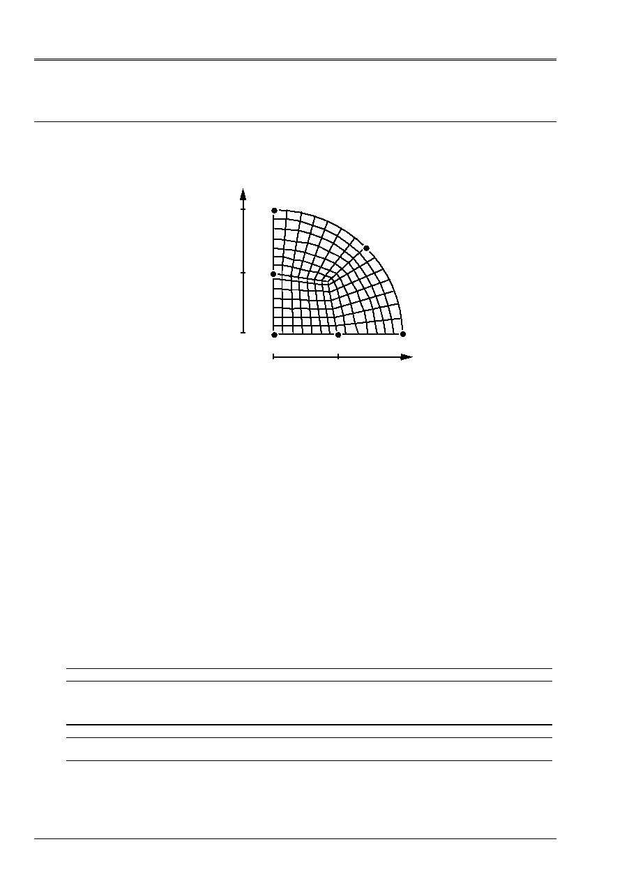
15.1 Characteristics of modeling
Axisymmetric element of hull SEG3, in theory of Coils-Kirchhoff: one does not consider
amendment of metric, the coefficient
A_CIS
is worth 10
6
.
y
O
D
With
X
p
0
0.5
1.0
Limiting conditions:
DDL_IMPO:
(NODE: WITH DX: 0., DY: 0., DRZ: 0.)
(NODE:
O
DRZ:
0.)
15.2 Characteristics of the mesh
A number of nodes: 21
A number of meshs and types: 10 SEG3
15.3 Functionalities
tested
Controls
Keys
“MECHANICAL” AFFE_MODELE “COQUE_AXIS”
ALL
[U4.22.01]
AFFE_CARA_ELEM HULL
A_CIS
MODI_METRIQUE
[U4.24.01]
AFFE_CHAR_MECA DDL_IMPO
FORCE_COQUE
GROUP_NO
ALL
[U4.25.01]
CALC_CHAM_ELEM “DEGE_ELNO_DEPL”
“EFGE_ELNO_DEPL”
“SIEF_ELGA_DEPL”
“SIGM_ELNO_DEPL”
[U4.61.01]
POST_RELEVE ACTION
NODE
“EXTRACTION”
[U4.74.03]

Code_Aster
®
Version
4.0
Titrate:
SSLS100 Plates circular embedded subjected to a pressure
Date:
22/12/98
Author (S):
P. MASSIN, D. BUI, A. LAULUSA
Key
:
V3.03.100-C AP
Ge:
17/24
Manual of Validation
V3.03 booklet: Linear statics of the hulls and the plates
HI-75/01/010/A
16 Results of modeling I
16.1 Values
tested
Not Reference
Coil-Kirchhoff
Aster %
difference
tolerance
O arrow
()
W R
170.6251 169.759 0.51 rel 10
2
D arrow
()
W R
95.9765 95.0383
0.98 rel 10
2
D rotation
()
R
255.940 257.120
0.46 rel 10
2
Not
Réfé rence
Aster
%
diff érence
K
rr
K
mall
K
xx
K
yy
K
xx
K
yy
D
170.625 511.875 IJK
60.0456 514.124
0.44
KLM
265.473
514.361
0.49
moy
162.760
514.242
4.61
0.46
Not
Réfé rence
Aster
%
diff érence
M
rr
M
mall
M
xx
M
yy
M
xx
M
yy
O 0.08125
0.08125
STU
0.08139
0.08139
0.18
0.18
To +0.125
+0.0375
ABC
+0.10717
+0.03215
14.2
14.2
D 0.02969
0.05156
IJK
KLM
moy
0.01962
0.03844
0.02903
0.04873
0.05439
0.05156
2.21
5.8
- 5.2
0.00
Note:
One notes the good results obtained, except on
K
rr
and
M
rr
, which utilizes derivative
of a higher nature less better calculated by the element.
16.2 Contents of the file results
Generalized displacements, deformations and efforts and stresses with the nodes.
16.3 Parameters
of execution
Version: 3.02.11
Machine: CRAY C90
System:
UNICOS 8.0
Overall dimension memory:
16 MW
Time CPU To use:
5.11 seconds
Code_Aster
®
Version
4.0
Titrate:
SSLS100 Plates circular embedded subjected to a pressure
Date:
22/12/98
Author (S):
P. MASSIN, D. BUI, A. LAULUSA
Key
:
V3.03.100-C AP
Ge:
18/24
Manual of Validation
V3.03 booklet: Linear statics of the hulls and the plates
HI-75/01/010/A
17 Modeling
J
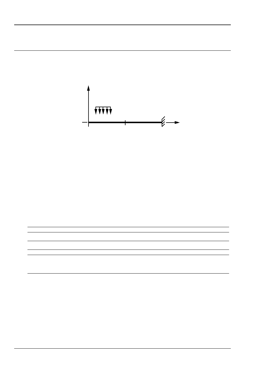
17.1 Characteristics of modeling
Axisymmetric element of hull SEG3, in theory of Mindlin-Reissner: one does not consider
amendment of metric, the coefficient
A_CIS
is worth 5/6.
y
O
D
With
X
p
0
0.5
1.0
Limiting conditions:
DDL_IMPO:
(NODE: WITH DX: 0., DY: 0., DRZ: 0.)
(NODE:
O
DRZ:
0.)
17.2 Characteristics of the mesh
A number of nodes: 21
A number of meshs and types: 10 SEG3
17.3 Functionalities
tested
Controls
Keys
“MECHANICAL” AFFE_MODELE “COQUE_AXIS”
ALL
[U4.22.01]
AFFE_CARA_ELEM HULL
A_CIS
MODI_METRIQUE
[U4.24.01]
AFFE_CHAR_MECA DDL_IMPO
FORCE_COQUE
GROUP_NO
ALL
[U4.25.01]
CALC_CHAM_ELEM “DEGE_ELNO_DEPL”
“EFGE_ELNO_DEPL”
“SIEF_ELGA_DEPL”
“SIGM_ELNO_DEPL”
[U4.61.01]
POST_RELEVE ACTION
NODE
“EXTRACTION”
[U4.74.03]

Code_Aster
®
Version
4.0
Titrate:
SSLS100 Plates circular embedded subjected to a pressure
Date:
22/12/98
Author (S):
P. MASSIN, D. BUI, A. LAULUSA
Key
:
V3.03.100-C AP
Ge:
19/24
Manual of Validation
V3.03 booklet: Linear statics of the hulls and the plates
HI-75/01/010/A
18 Results of modeling J
18.1 Values
tested
Not Reference
REISSNER
Aster %
difference
tolerance
O arrow
()
W R
178.424 178.368
0.03
rel 10
2
D arrow
()
W R
101.827 101.7769
0.05
rel 10
2
D rotation
()
R
255.940 256.001
0.02
rel 10
2
Not
Réfé rence
Aster
%
diff érence
K
rr
K
mall
K
xx
K
yy
K
xx
K
yy
D
170.625 511.875 IJK
167.892 512.050 - 1.62 0.03
KLM
178.920
511.952
4.86
0.01
moy
173.406
512.001
1.60
0.02
Not
Réfé rence
Aster
%
diff érence
M
rr
M
mall
M
xx
M
yy
M
xx
M
yy
O
0.08125 0.08125 STU
0.08175 0.08175 0.62
0.62
To +0.125
+0.0375
ABC
0.12373
+0.03712
1.02
1.01
D 0.02969
0.05156
IJK
KLM
moy
0.02944
0.03045
0.02994
0.05150
0.05179
0.05165
- 0.85
2.49
0.85
- 0.11
0.46
0.17
Note:
One notes the good results obtained, except on
K
rr
and
M
rr
, which utilizes derivative
of a higher nature less better calculated by the element.
18.2 Contents of the file results
Generalized displacements, deformations and efforts and stresses with the nodes.
18.3 Parameters
of execution
Version: 3.02.11
Machine: CRAY C90
System:
UNICOS 8.0
Overall dimension memory:
16 MW
Time CPU To use:
4.99 seconds
Code_Aster
®
Version
4.0
Titrate:
SSLS100 Plates circular embedded subjected to a pressure
Date:
22/12/98
Author (S):
P. MASSIN, D. BUI, A. LAULUSA
Key
:
V3.03.100-C AP
Ge:
20/24
Manual of Validation
V3.03 booklet: Linear statics of the hulls and the plates
HI-75/01/010/A
19 Modeling
K
19.1 Characteristics of modeling
Modeling: Element of hull
COQUE_3D
MEC3QU9H
C
E
O
D
With
B
Limiting conditions:
DDL_IMPO:
in all the nodes of the arc
ABC
(Group_no:ABC DX:0., DY: 0., DZ: 0.)
DRX:0., DRY:0., DRZ:0.)
segment] OA]
(Group_no:OA DY:0., DRX:0., DRZ:0.)
segment] OC]
(Group_no:OC DX:0., DRY:0., DRZ:0.)
with the node O
(Group_no:O DX:0., DY:0., DRX:0., DRY:0., DRZ:0.)
Names of the nodes:
Point 0
meshs: M1
Not A
meshs: M21
Not B
meshs: M25
Not C
meshs: M5
Not D
meshs: M11
Not E
meshs: M3
19.2 Characteristics of the mesh
A number of nodes: 96
A number of meshs and types: 25 QUAD9
19.3 Functionalities
tested
Controls
Keys
AFFE_CARA_ELEM HULL
[U4.24.01]
AFFE_CHAR_MECA DDL_IMPO
GROUP_NO
[U4.25.01]
FORCE_COQUE
NEAR
F3
GRAVITY
AFFE_MATERIAU ALL
[U4.23.02]
“MECHANICAL” AFFE_MODELE “COQUE_3D”
ALL
[U4.22.01]
CALC_CHAM_ELEM “EFFO_ELNO_DEPL”
[U4.61.01]
“SIGM_ELNO_DEPL”
DEFI_MATERIAU ELAS
[U4.23.01]
POST_RELEVE ACTION
OPERATION “EXTRACTION”
[U4.74.03]
VALE_TEST
EPSI_TEST

Code_Aster
®
Version
4.0
Titrate:
SSLS100 Plates circular embedded subjected to a pressure
Date:
22/12/98
Author (S):
P. MASSIN, D. BUI, A. LAULUSA
Key
:
V3.03.100-C AP
Ge:
21/24
Manual of Validation
V3.03 booklet: Linear statics of the hulls and the plates
HI-75/01/010/A
20 Results of modeling K
20.1 Values
tested
Not Reference
REISSNER
Aster %
difference
tolerance
O
178.419 178.39
0.016 rel 10
2
With
0. eps
- ABS 10
10
B
0. eps
- ABS 10
10
C W
(R)
0. eps
- ABS 10
10
D
101.82 101.79
0.029 rel 10
2
E
101.82 101.79
0.029 rel 10
2
Not Reference
Aster
M
rr
M
Sm/2
M
xx
M
yy
Sm/2
O 0.08125
0.08125
0.08125
0.08342
0.08342
0.08342
To +0.125
+0.0375
+0.08125
0.03675
0.1234
0.08007
C +0.125
+0.0375
+0.08125
0.1243
0.03582
0.08006
D 0.02969
0.05156
0.04062
0.05241
0.02971
0.04106
E 0.02969
0.05156
0.04062
0.02958
0.05254
0.04106
Not
% difference
Relative tolerance
M
xx
M
yy
Sm/2
O 2.67
2.67
2.67 3.
To 2.
1.28
1.45 3.
C 0.56
4.48
1.46 5.
D 1.65
0.067
1.08 2.
E 0.37
1.9
0.95 2.
·
with eps 10
14
and % difference on the absolute values
Note:
The test of the values is carried out automatically using the functionalities offered by
procedure
POST_RELEVE
:
·
extraction on the nodes corresponding to the points observed of the average values of
components
M
xx
and
M
yy
; these values are extracted from the field
“EFGE_ELNO_DEPL”
, and
the average is calculated for all the liquid assets on the meshs which contain it
node observed,
·
calculation of the variation compared to the value of reference provided by observing the rules of
correspondence enters
M
xx
,
M
yy
and
M
rr
,
M
data page 3.
Contents of the file results
Values at the points of observation of displacements and moments realized.
20.2 Parameters
of execution
Version: 4.00.14
Machine: CRAY C90
System:
UNICOS 8.0
Overall dimension memory:
16 MW
Time CPU To use:
8.77 seconds
Code_Aster
®
Version
4.0
Titrate:
SSLS100 Plates circular embedded subjected to a pressure
Date:
22/12/98
Author (S):
P. MASSIN, D. BUI, A. LAULUSA
Key
:
V3.03.100-C AP
Ge:
22/24
Manual of Validation
V3.03 booklet: Linear statics of the hulls and the plates
HI-75/01/010/A
21 Modeling
L
21.1 Characteristics of modeling
Modeling: Element of
COQUE_3D
MEC3TR7H
C
E
O
D
With
B
Limiting conditions:
DDL_IMPO:
in all the nodes of the arc
ABC
(Group_no:ABC DX:0., DY: 0., DZ: 0.)
DRX:0., DRY:0., DRZ:0.)
segment] OA]
(Group_no:OA DY:0., DRX:0., DRZ:0.)
segment] OC]
(Group_no:OC DX:0., DRY:0., DRZ:0.)
with the node O
(Group_no:O DX:0., DY:0., DRX:0., DRY:0., DRZ:0.)
Names of the nodes:
Point 0
meshs: M1 and m2
Not A
meshs: M41
Not B
meshs: M49 and M50
Not C
meshs: M10
Not D
meshs: M21
Not E
meshs: M6
21.2 Characteristics of the mesh
A number of nodes: 121
A number of meshs and types: 50 TRIA7
21.3 Functionalities
tested
Controls
Keys
AFFE_CARA_ELEM HULL
[U4.24.01]
AFFE_CHAR_MECA DDL_IMPO
GROUP_NO
[U4.25.01]
FORCE_COQUE
NEAR
F3
GRAVITY
AFFE_MATERIAU ALL
[U4.23.02]
“MECHANICAL” AFFE_MODELE “COQUE_3D”
ALL
[U4.22.01]
CALC_CHAM_ELEM “EFFO_ELNO_DEPL”
[U4.61.01]
“SIGM_ELNO_DEPL”
DEFI_MATERIAU ELAS
[U4.23.01]
POST_RELEVE ACTION
OPERATION “EXTRACTION”
[U4.74.03]
VALE_TEST
EPSI_TEST
Code_Aster
®
Version
4.0
Titrate:
SSLS100 Plates circular embedded subjected to a pressure
Date:
22/12/98
Author (S):
P. MASSIN, D. BUI, A. LAULUSA
Key
:
V3.03.100-C AP
Ge:
23/24
Manual of Validation
V3.03 booklet: Linear statics of the hulls and the plates
HI-75/01/010/A
22 Results of modeling L
22.1 Values
tested
Not Reference
REISSNER
Aster %
difference
tolerance
O
178.419 178.18
0.13
rel 10
2
With
0. eps
- ABS 10
10
B
0. eps
- ABS 10
10
C W
(R)
0. eps
- ABS 10
10
D
101.82 101.46
0.35 rel 10
2
E
101.82 101.46
0.35 rel 10
2
Not Reference
Aster
M
rr
M
Sm/2
M
xx
M
yy
Sm/2
O 0.08125
0.08125
0.08125
0.08360
0.08360
0.08360
To +0.125
+0.0375
+0.08125
0.03741
0.12294
0.08017
C +0.125
+0.0375
+0.08125
0.12325
0.03711
0.08018
D 0.02969
0.05156
0.04062
0.05117
0.02907
0.04012
E 0.02969
0.05156
0.04062
0.02905
0.05119
0.04012
Not
% difference
Relative tolerance
M
xx
M
yy
Sm/2
O 2.89
2.89
2.89 3.
With 0.24
1.65
1.33 3.
C 1.4
1.04
1.32 3.
D 0.76
2.09
1.23 3.
E 2.16
0.72
1.23 3.
·
with eps 10
14
and % difference on the absolute values
Note:
The test of the values is carried out automatically using the functionalities offered by
procedure
POST_RELEVE
:
·
extraction on the nodes corresponding to the points observed of the average values of
components
M
xx
and
M
yy
; these values are extracted from the field
“EFGE_ELNO_DEPL”
, and
the average is calculated for all the liquid assets on the meshs which contain it
node observed,
·
calculation of the variation compared to the value of reference provided by observing the rules of
correspondence enters
M
xx
,
M
yy
and
M
rr
,
M
data page 3.
Contents of the file results
Values at the points of observation of displacements and moments realized.
22.2 Parameters
of execution
Version: 4.00.14
Machine: CRAY C90
System:
UNICOS 8.0
Overall dimension memory:
16 MW
Time CPU To use:
9.29 seconds

Code_Aster
®
Version
4.0
Titrate:
SSLS100 Plates circular embedded subjected to a pressure
Date:
22/12/98
Author (S):
P. MASSIN, D. BUI, A. LAULUSA
Key
:
V3.03.100-C AP
Ge:
24/24
Manual of Validation
V3.03 booklet: Linear statics of the hulls and the plates
HI-75/01/010/A
23 Summary of the results
% of the differences compared to the reference solutions
DKT DKQ
DST
DSQ
Q4G
Mode. With
Coil
B
Kirchhoff
E
Coil-Kirchhoff
F
Reissner
G
Reissner
H
Reissner
Point 50
nodes
76 TRIA3
170 nodes
296 TRIA3
169 nodes
147 QUAD4
170 nodes
296 TRIA3
169 nodes
147 QUAD4 169 nodes
147 QUAD4
O
()
W R
0.76 +0.12 +0.22
+0.74 +0.19 0.08
D
()
W R
0.23 +0.18 +0.23
+0.77 +0.19 0.28
E
()
W R
0.25 +0.24 +0.23
+0.84 +0.19 0.28
F
()
W R
0.32 +0.22 +0.20
+0.75 +0.14 0.34
COQU_AXIS MEC3QU9H
MEC3TR7H
Mode. I
Coil-Kirchhoff
J
Reissner
K
L
Point 21
nodes
10 SEG3
96
nodes
25 QUAD9
121 nodes
50 TRIA7
O
()
W R
+0.51 0.03
0.16 0.13
D
()
W R
+0.28 0.05
0.029
0.35
E
()
W R
- -
0.029
0.35
F
()
W R
- +0.22
- -
DKT DKQ
DST
DSQ
Q4G
Mode. With
Coil
B
Kirchhoff
E
Coil-Kirchhoff
F
Reissner
G
Reissner
H
Reissner
Point 50
nodes
76 TRIA3
170 nodes
296 TRIA3
169 nodes
147 QUAD4
170 nodes
296 TRIA3
169 nodes
147 QUAD4 169 nodes
147 QUAD4
O
Sm/2
1.15
+0.19
+0.46
+1.04
0.33
0.07
With
Sm/2
+0.81
+4.02
+0.49
+5.26
+3.79
10.73
B
Sm/2
+4.58
+2.64
+0.20
+2.02
+1.69
10.95
C
Sm/2
+0.75
+4.13
+0.45
+5.34
+3.64
10.69
D
Sm/2
+4.55
+1.99
+2.71
+2.07
+0.40
+0.74
E
Sm/2
+4.55
+2.19
+2.71
+2.29
+0.40
+0.74
F
Sm/2
+1.71
+2.05
0.79
+1.19
+17.80
0.94
COQU_AXIS MEC3QU9H
MEC3TR7H
Mode. I
Coil-Kirchhoff
J
Reissner
K
L
Point 21
nodes
10 SEG3
96
nodes
25 QUAD9
121 nodes
50 TRIA7
O
Sm/2
+0.18 +0.62
2.67 2.89
With
Sm/2
+14.2 1.01
1.45 1.33
B
Sm/2
- -
- -
C
Sm/2
- -
1.46
1.32
D
Sm/2
+0.84 0.85
1.08 1.23
E
Sm/2
- -
0.95
1.23
F
Sm/2
- -
- -
Note:
Concerning the efforts, direct calculation with the nodes leads to variations in several nodes,
in particular at the point F in DSQ and on the edge ABC in Q4
.