
Code_Aster
®
Version
7.2
Titrate:
SSLS101 Plates circular posed subjected to a uniform pressure
Date:
05/01/04
Author (S):
J.M. PROIX, P. MASSIN, D. BUI, A. LAULUSA
Key
:
V3.03.101-D
Page:
1/22
Manual of Validation
V3.03 booklet: Linear statics of the hulls and the plates
HT-66/03/008/A
Organization (S):
EDF-R & D/AMA, SAMTECH
Manual of Validation
V3.03 booklet: Linear statics of the hulls and the plates
Document: V3.03.101
SSLS101 - Plate circular posed subjected
with a uniform pressure
Summary:
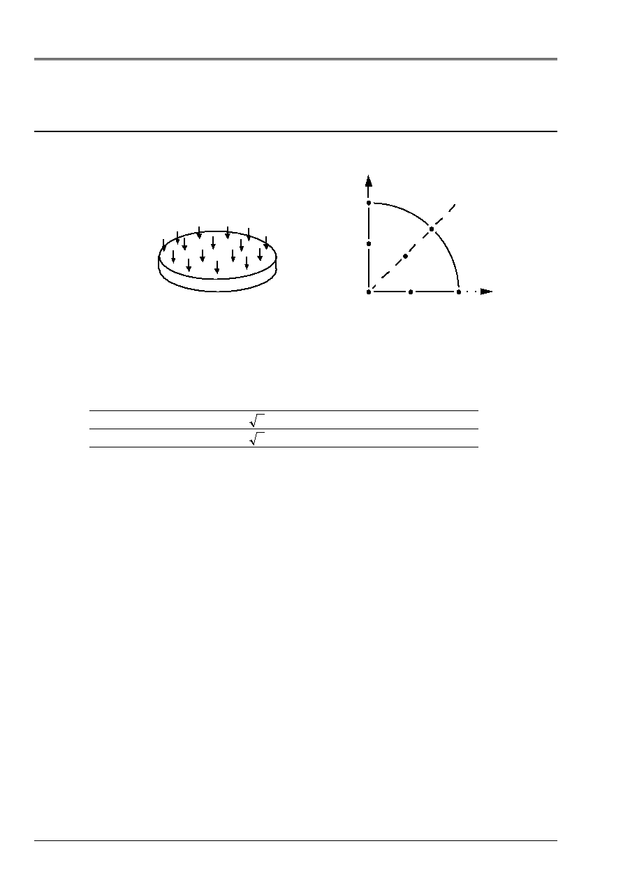
One treats the case of a circular plate posed on the edge in linear elasticity under 3 loadings (weight
clean, pressure, effort distributed constant) which gives the same deformation.
The first two modelings make it possible to evaluate the influence of the mesh.
The test gathers 9 modelings (model Coils-Kirchhoff, Mindlin-Reissner and
COQUE_3D
and SHB8).
Code_Aster
®
Version
7.2
Titrate:
SSLS101 Plates circular posed subjected to a uniform pressure
Date:
05/01/04
Author (S):
J.M. PROIX, P. MASSIN, D. BUI, A. LAULUSA
Key
:
V3.03.101-D
Page:
2/22
Manual of Validation
V3.03 booklet: Linear statics of the hulls and the plates
HT-66/03/008/A
1
Problem of reference
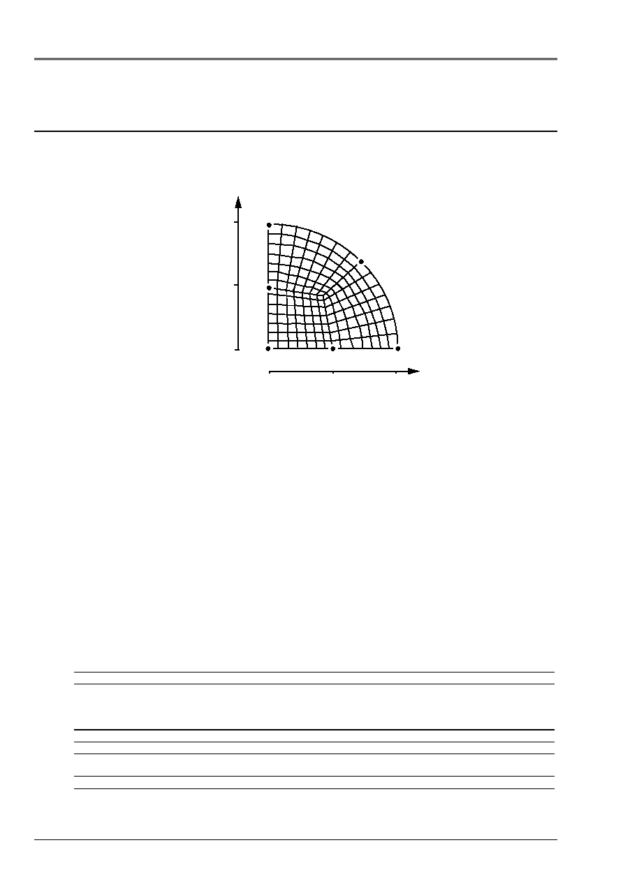
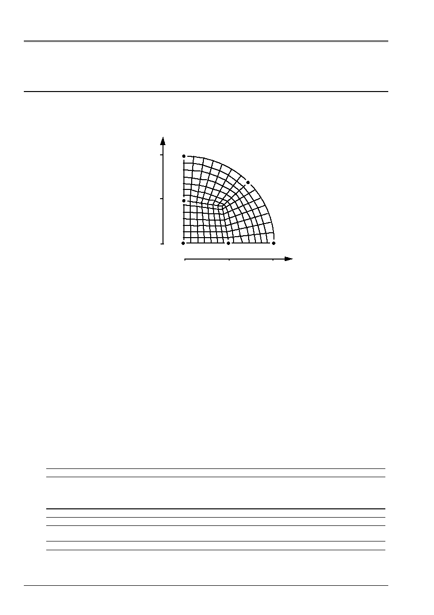
1.1 Geometry
With
B
C
O
D
E
F
y
X
1/4 of plate
Radius
R = 1 m
Thickness
T = 0.1 m
Co-ordinates of the points:
O WITH B C D E F
X 0.
1.
2 2
/
0. 0.5
0. 0.4
y 0.
0.
2 2
/
1. 0. 0.5
0.4
Z
0. 0. 0. 0. 0. 0. 0.
1.2
Material properties
E = 1. AP
= 0.3
= 1. kg/m
3
1.3
Boundary conditions and loadings
Simple support on the edge of the plate:
in all the points P such as COp = R: U = v = W = 0
FORCE_COQUE
Uniform pressure
P = 1 NR/m
2
FORCE_COQUE
Charge distributed normal
F3 = 1 NR/m
2
GRAVITY
G = 10 m/s
2
according to Z
from where
FZ =
WP = 1 NR/m
2
These three loadings lead to the same solution.
Code_Aster
®
Version
7.2
Titrate:
SSLS101 Plates circular posed subjected to a uniform pressure
Date:
05/01/04
Author (S):
J.M. PROIX, P. MASSIN, D. BUI, A. LAULUSA
Key
:
V3.03.101-D
Page:
3/22
Manual of Validation
V3.03 booklet: Linear statics of the hulls and the plates
HT-66/03/008/A
2
Reference solution
2.1
Method of calculation used for the reference solution
Two reference solutions are usable, for the calculation of the deformation, according to the theory of plate
used:
·
the theory of Coils-Kirchhoff, usually used for the plates known as “thin”, that one
will retain for modelings A, B and E,
·
the theory of Reissner, including the effects of shearing for the plates known as “thick”,
that one will retain for modelings F, G and H.
In any distant point of
R
center of the plate
(
)
R R
, one has for the calculation of the arrow:
()
(
)
()
.
(Reissner)
or
Kirchhoff)
(Coils
and
with
-
=
=
-
=
-
+
+
-
+
-
-
=
-
1
1
5
16
0
1
12
1
3
2
1
1
64
2
2
3
2
2
2
2
4
R
T
T
E
D
R
R
R
R
D
R
P
R
W
For the calculation of the moments the two theories lead to the same expressions:
()
(
)
()
(
)
M
R
P R
R
R
M
R
P R
R
R
rr
=
+
-
=
+
- ++
2
2
2
2
16
3
1
16
3
1 1 3
3
In the center of the plate:
()
(
)
()
(
)
()
()
(
)
+
-
=
=
+
+
+
-
=
+
+
-
=
-
3
16
0
0
1
5
64
0
1
5
64
0
2
4
4
R
P
M
M
D
R
P
W
D
R
P
W
rr
Reissner
or
Kirchhoff
Coil
Note:
Code_Aster calculates the moments with the nodes of each finite element in the reference mark of
reference defined by the external normal and the reference axes defined on the hull (see
AFFE_CARA_ELEM
in the documentation of use).
The value of the moment
M
xx
(or
M
yy
), extracted the field
“EFGE_ELNO_DEPL”
, in a node
belonging to several finite elements can be regarded as being the average of
computed values on the elements which have this joint node. This average can be
obtained by the procedure
POST_RELEVE
[U4.74.03].
For each node, one a:
(
)
(
)
M
M
M
M
Sm
rr
xx
yy
+
=
+
=
(
)
for the point O
for the points A and D
and
for the points C and E
and
for the points B and F
M
M
M
M
M
M
M
M
M
M
M
M
M
M
M
M
xx
yy
rr
xx
rr
yy
xx
yy
rr
xx
yy
rr
=
=
=
=
=
=
=
=
=
+
/2
2.2
Results of reference
Arrow and moments at the points: O, A, B C, D E, F.
2.3
Uncertainty on the solution
Analytical solution.
2.4 References
bibliographical
[1]
TIMOSHENKO and WOINOWSKY-KRIEGER, Plates and hulls, Béranger Edition - (1961).

Code_Aster
®
Version
7.2
Titrate:
SSLS101 Plates circular posed subjected to a uniform pressure
Date:
05/01/04
Author (S):
J.M. PROIX, P. MASSIN, D. BUI, A. LAULUSA
Key
:
V3.03.101-D
Page:
4/22
Manual of Validation
V3.03 booklet: Linear statics of the hulls and the plates
HT-66/03/008/A
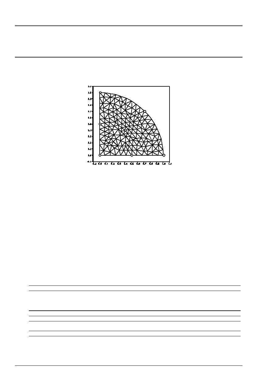
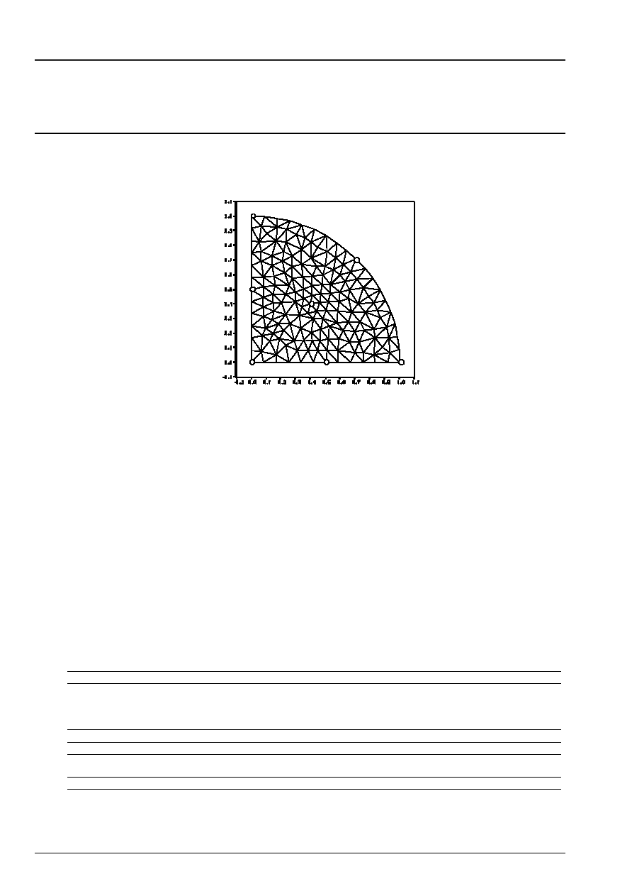
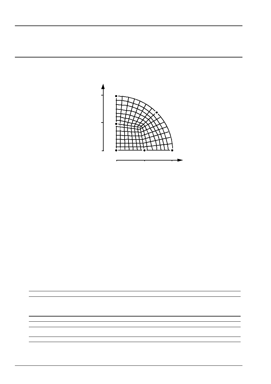
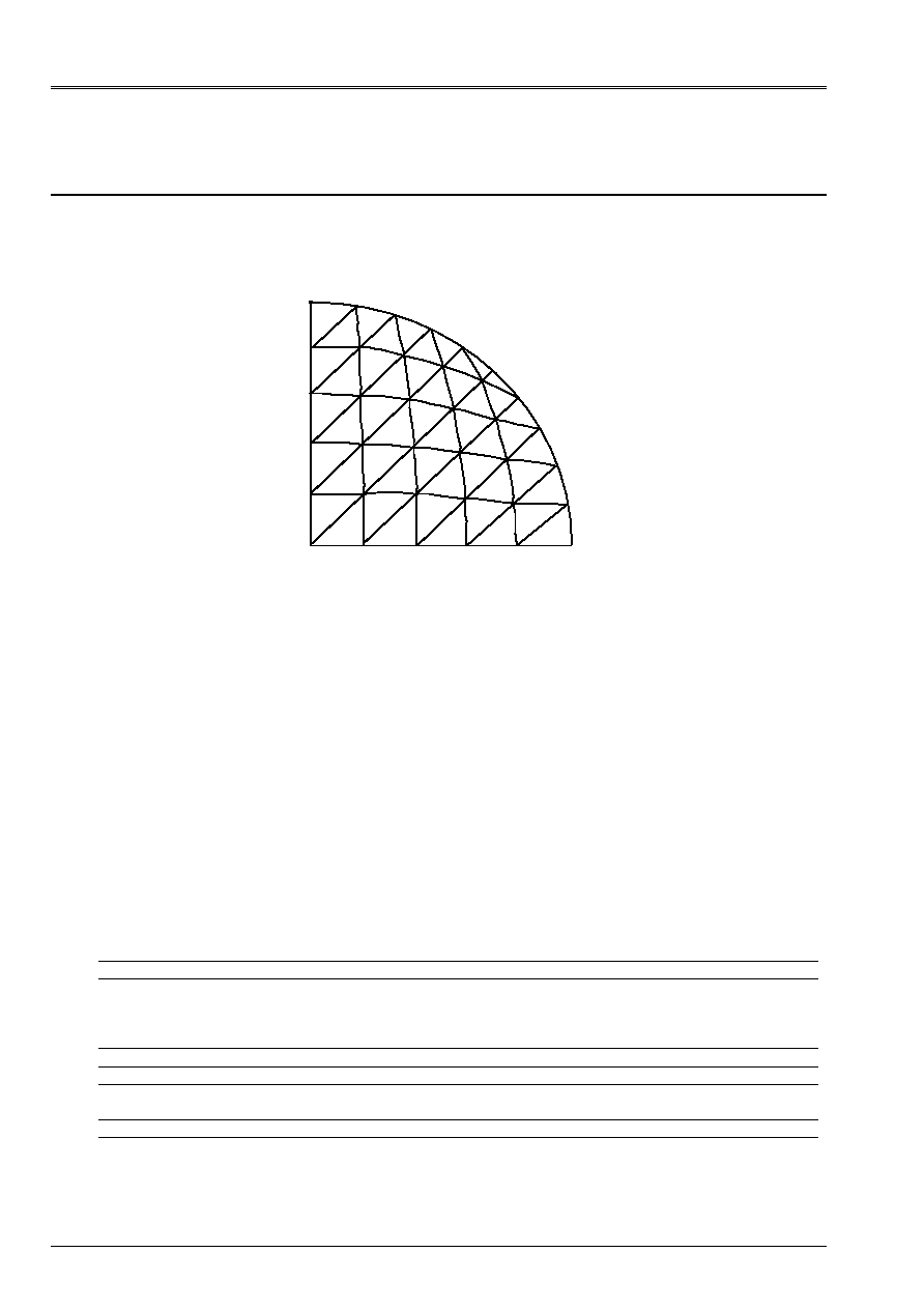
3 Modeling
With
3.1
Characteristics of modeling
Element of hull DKT (modeling of a quarter of plate)
O
With
B
C
E
D
F
3.1.1 Conditions
limits
in all the nodes of the arc ABC
:
DX: 0., DY: 0., DZ: 0.
in all the nodes of segment] OA [
:
DY: 0., DRX:0., DRZ:0.
in all the nodes of segment] OC [:
DX: 0., DRY:0., DRZ:0.
with the node O
:
DX: 0., DY: 0., DRX:0., DRY:0., DRZ:0.
Point 0
meshs: M30 M33
Not A
meshs: M76
Not B
meshs: M39 M40 M51
Not C
meshs: M1
Not D
meshs: M55 M56 M65
Not E
meshs: M8 M17 M18
Not F
meshs: M34 M35 M37 M41 M46 M47 M48
3.2
Characteristics of the mesh
A number of nodes: 50
A number of meshs and types: 76 TRIA3
3.3 Functionalities
tested
Controls
AFFE_CARA_ELEM HULL
THICK
ANGL_REP
AFFE_CHAR_MECA DDL_IMPO
FORCE_COQUE
GROUP_NO
NEAR
AFFE_MATERIAU ALL
“MECHANICAL” AFFE_MODELE “DKT” ALL
CALC_CHAM_ELEM “EFGE_ELNO_DEPL”
“SIGM_ELNO_DEPL”
DEFI_MATERIAU ELAS
POST_RELEVE ACTION
OPERATION
VALE_TEST
EPSI_TEST
“EXTRACTION”
Code_Aster
®
Version
7.2
Titrate:
SSLS101 Plates circular posed subjected to a uniform pressure
Date:
05/01/04
Author (S):
J.M. PROIX, P. MASSIN, D. BUI, A. LAULUSA
Key
:
V3.03.101-D
Page:
5/22
Manual of Validation
V3.03 booklet: Linear statics of the hulls and the plates
HT-66/03/008/A
4
Results of modeling A
4.1 Values
tested
Identification Reference
Aster %
difference
0
()
W R
695.6256
687.95
1.10
D
()
W R
489.727
484.76
1.01
E
()
W R
489.727
484.69
1.03
F
()
W R
435.8974
431.33
1.05
Reference
Not
M
rr
M
2
/
Sm
O 0.20625
0.20625
0.20625
To 0.
0.0875
0.04375
B 0.
0.0875
0.04375
C 0.
0.0875
0.04375
D 0.15469
0.17656
0.1656
E 0.15469
0.17656
0.1656
F 0.14025
0.16825
0.15425
Aster
Not
M
xx
M
yy
2
/
Sm
O 0.20377
0.20382
0.20379
To 0.00992
0.08265
0.04628
B 0.03827
0.03771
0.03799
C 0.08263
0.00990
0.04626
D 0.15516
0.17680
0.16597
E 0.17677
0.15509
0.16593
F 0.15307
0.15342
0.15324
% difference (% difference on the absolute values)
Not
M
xx
M
yy
Sm/2
Relative tolerance
O
1.20 1.18 1.19
1.5
With
- 5.54
+5.79
-/6.
B
12.5 13.8 13.1
13./14.
C
5.56 - +5.73
6./-
D
0.30 0.14
+0.2
0.5
E
0.12 0.26
+0.19
0.3
F
+9.15 8.81 0.66
10.
Code_Aster
®
Version
7.2
Titrate:
SSLS101 Plates circular posed subjected to a uniform pressure
Date:
05/01/04
Author (S):
J.M. PROIX, P. MASSIN, D. BUI, A. LAULUSA
Key
:
V3.03.101-D
Page:
6/22
Manual of Validation
V3.03 booklet: Linear statics of the hulls and the plates
HT-66/03/008/A
5 Modeling
B
5.1
Characteristics of modeling
Element of hull DKT (modeling of a quarter of plate)
-
C
O
With
D
B
E
F
5.1.1 Conditions
limits
in all the nodes of the arc ABC
:
DX: 0., DY: 0., DZ: 0.
in all the nodes of segment] OA [
:
DY: 0., DRX:0., DRZ:0.
in all the nodes of segment] OC [
:
DX: 0., DRY:0., DRZ:0.
with the node O
:
DX: 0., DY: 0., DRX:0., DRY:0., DRZ:0.
Not O
meshs: M1 m2
Not A
meshs: M248 M255
Not B
meshs: M292 M293 M296
Not C
meshs: M74 M75
Not D
meshs: M76 M108 M109
Not E
meshs: M34 M40 M41
Not F
meshs: M122 M123 M124 M148 M152 M153
5.2
Characteristics of the mesh
A number of nodes: 170
A number of meshs and types: 296 TRIA3
5.3 Functionalities
tested
Controls
AFFE_CARA_ELEM HULL
AFFE_CHAR_MECA DDL_IMPO
FORCE_COQUE
GROUP_NO
NEAR
F3
GRAVITY
AFFE_MATERIAU ALL
“MECHANICAL” AFFE_MODELE “DKT” ALL
CALC_CHAM_ELEM “EFGE_ELNO_DEPL”
“SIGM_ELNO_DEPL”
DEFI_MATERIAU ELAS
POST_RELEVE ACTION
OPERATION
VALE_TEST
EPSI_TEST
“EXTRACTION”
Code_Aster
®
Version
7.2
Titrate:
SSLS101 Plates circular posed subjected to a uniform pressure
Date:
05/01/04
Author (S):
J.M. PROIX, P. MASSIN, D. BUI, A. LAULUSA
Key
:
V3.03.101-D
Page:
7/22
Manual of Validation
V3.03 booklet: Linear statics of the hulls and the plates
HT-66/03/008/A
6
Results of modeling B
6.1 Values
tested
Identification Reference Aster %
difference
O
()
W R
695.6256
694.97
0.09
D
()
W R
489.727
489.24
0.1
E
()
W R
489.727
489.31
0.09
F
()
W R
435.8974
435.48
0.09
Reference
Not
M
rr
M
Sm/2
O 0.20625
0.20625
0.20625
To 0.
0.0875
0.04375
B 0.
0.0875
0.04375
C 0.
0.0875
0.04375
D 0.15469
0.17656
0.1656
E 0.15469
0.17656
0.1656
F 0.14025
0.16825
0.15425
Aster
Not
M
xx
M
yy
Sm/2
O 0.20631
0.20609
0.20620
To 0.00238
0.08459
0.04348
B 0.4132
0.04134
0.04133
C 0.08460
0.00238
0.04349
D 0.15516
0.17727
0.16621
E 0.17739
0.15523
0.16631
F 0.15461
0.15468
0.15464
% difference (% difference on the absolute values)
Not
M
xx
M
yy
Sm/2
Relative tolerance
O
0.03 0.7
0.02
0.1
With
- 3.32
0.06
-/3.5
B
5.56 5.51 5.53
6.
C
3.31 - 0.06
3.5/-
D
+0.30 +0.40 +0.35
0.5
E
+0.47 +0.35 +0.42
0.5
F
+0.23 +0.28 +0.25
0.3

Code_Aster
®
Version
7.2
Titrate:
SSLS101 Plates circular posed subjected to a uniform pressure
Date:
05/01/04
Author (S):
J.M. PROIX, P. MASSIN, D. BUI, A. LAULUSA
Key
:
V3.03.101-D
Page:
8/22
Manual of Validation
V3.03 booklet: Linear statics of the hulls and the plates
HT-66/03/008/A
7 Modeling
C
7.1
Characteristics of modeling
Element of hull SHB8 (modeling of a quarter of plate)
C
B
With
D
E
0.0
0.5
1.0
0.0
1.0
0.5
O
7.1.1 Conditions
limits
in all the nodes of the arc ABC
:
DX: 0., DY: 0., DZ: 0.
in all the nodes of face] OA [
:
DY: 0.,
in all the nodes of face] OC [
:
DX: 0.,
with the node O
:
DX: 0., DY: 0.,
The mesh is built starting from the surface mesh of modeling E, by thickening, with
aid
CREA_MAILLAGE
/
COQU_VOLU
. One builds 2 layers of meshs HEXA8.
7.2
Characteristics of the mesh
A number of nodes: 338
A number of meshs and types: 147 HEXA8
7.3 Functionalities
tested
Controls
AFFE_CHAR_MECA DDL_IMPO
FORCE_FACE
FORCE_INTERN
GROUP_NO
F2
F2
GRAVITY
AFFE_MATERIAU ALL
“MECHANICAL” AFFE_MODELE SHB8
ALL
CALC_CHAM_ELEM “EFGE_ELNO_DEPL”
“SIGM_ELNO_DEPL”
DEFI_MATERIAU ELAS
CREA_MAILLAGE COQU_VOLU
CALC_CHAM_ELEM OPTION
COOR_ELGA

Code_Aster
®
Version
7.2
Titrate:
SSLS101 Plates circular posed subjected to a uniform pressure
Date:
05/01/04
Author (S):
J.M. PROIX, P. MASSIN, D. BUI, A. LAULUSA
Key
:
V3.03.101-D
Page:
9/22
Manual of Validation
V3.03 booklet: Linear statics of the hulls and the plates
HT-66/03/008/A
8
Results of modeling C
8.1 Values
tested
Identification Reference
Aster %
difference
O
()
W R
695.6256
698.6
0.4
D
()
W R
489.727
491.4
0.3
E
()
W R
489.727
491.4
0.3
F
()
W R
435.8974
436.6
0.2
Code_Aster
®
Version
7.2
Titrate:
SSLS101 Plates circular posed subjected to a uniform pressure
Date:
05/01/04
Author (S):
J.M. PROIX, P. MASSIN, D. BUI, A. LAULUSA
Key
:
V3.03.101-D
Page:
10/22
Manual of Validation
V3.03 booklet: Linear statics of the hulls and the plates
HT-66/03/008/A
9 Modeling
E
9.1
Characteristics of modeling
Element of hull DKQ (modeling of a quarter of plate)
C
B
With
D
E
0.0
0.5
1.0
0.0
1.0
0.5
O
9.1.1 Conditions
limits
in all the nodes of the arc ABC
:
DX: 0., DY: 0., DZ: 0.
in all the nodes of segment] OA [
:
DY: 0., DRX:0., DRZ:0.
in all the nodes of segment] OC [
:
DX: 0., DRY:0., DRZ:0.
with the node O
:
DX: 0., DY: 0., DRX:0., DRY:0., DRZ:0.
Not O
meshs: M1
Not A
meshs: M147
Not B
meshs: M98 M111
Not C
meshs: M14
Not D
meshs: M85 M99
Not E
meshs: M7 M8
Not F
meshs: M91 M92 M105
9.2
Characteristics of the mesh
A number of nodes: 169
A number of meshs and types: 147 QUAD4
9.3 Functionalities
tested
Controls
AFFE_CARA_ELEM HULL
AFFE_CHAR_MECA DDL_IMPO
FORCE_COQUE
GROUP_NO
NEAR
F3
GRAVITY
AFFE_MATERIAU ALL
“MECHANICAL” AFFE_MODELE “DKT” ALL
CALC_CHAM_ELEM “EFGE_ELNO_DEPL”
“SIGM_ELNO_DEPL”
DEFI_MATERIAU ELAS
POST_RELEVE ACTION
OPERATION
VALE_TEST
EPSI_TEST
“EXTRACTION”
Code_Aster
®
Version
7.2
Titrate:
SSLS101 Plates circular posed subjected to a uniform pressure
Date:
05/01/04
Author (S):
J.M. PROIX, P. MASSIN, D. BUI, A. LAULUSA
Key
:
V3.03.101-D
Page:
11/22
Manual of Validation
V3.03 booklet: Linear statics of the hulls and the plates
HT-66/03/008/A
10 Results of modeling E
10.1 Values
tested
Identification Reference
Aster %
difference
O
()
W R
695.6256
695.01
0.09
D
()
W R
489.727
489.20
0.11
E
()
W R
489.727
489.20
0.12
F
()
W R
435.8974
435.38
0.09
Reference
Not
M
rr
M
Sm/2
O
0.20625 0.20625 0.20625
To 0.
0.0875
0.04375
B 0.
0.0875
0.04375
C 0.
0.0875
0.04375
D
0.15469 0.17656 0.1656
E
0.15469 0.17656 0.1656
F
0.14025 0.16825 0.15425
Aster
Not
M
xx
M
yy
Sm/2
O
0.20639 0.20639 0.20639
To +0.00036
0.087104
0.04353
B
0.04330 0.04332 0.04331
C 0.087133
+0.00034
0.04355
D
0.15506 0.17790 0.16648
E
0.17790 0.15507 0.16648
F
0.15380 0.15377 0.15378
% difference (% difference on the absolute values)
Not
M
xx
M
yy
Sm/2
Relative tolerance
O
+0.07 +0.07 +0.07
0.1
With
- 0.45
0.49
-/0.5
B
1.02 +0.98 +1.0
1.1
C
0.42 - 0.46
0.5/-
D
+0.24 +0.76 +0.5
1.
E
+0.76 +0.24 +0.5
1.
F
0.29 0.31 0.3
0.5
Code_Aster
®
Version
7.2
Titrate:
SSLS101 Plates circular posed subjected to a uniform pressure
Date:
05/01/04
Author (S):
J.M. PROIX, P. MASSIN, D. BUI, A. LAULUSA
Key
:
V3.03.101-D
Page:
12/22
Manual of Validation
V3.03 booklet: Linear statics of the hulls and the plates
HT-66/03/008/A
11 Modeling
F
11.1 Characteristics of modeling
Element of hull DST (modeling of a quarter of plate)
C
O
With
D
B
E
F
11.1.1 Limiting conditions
in all the nodes of the arc ABC
:
DX: 0., DY: 0., DZ: 0.
in all the nodes of segment] OA [
:
DY: 0., DRX:0., DRZ:0.
in all the nodes of segment] OC [
:
DX: 0., DRY:0., DRZ:0.
with the node O
:
DX: 0., DY: 0., DRX:0., DRY:0., DRZ:0.
Not O
meshs: M1 m2
Not A
meshs: M248 M255
Not B
meshs: M3292 M293 M296
Not C
meshs: M74 M75
Not D
meshs: M76 M108 M109
Not E
meshs: M34 M40 M41
Not F
meshs: M122 M123 M124 M148 M152 M153
11.2 Characteristics of the mesh
A number of nodes: 170
A number of meshs and types: 296 TRIA3
11.3 Functionalities
tested
Controls
AFFE_CARA_ELEM HULL
AFFE_CHAR_MECA DDL_IMPO
FORCE_COQUE
GROUP_NO
NEAR
F3
GRAVITY
AFFE_MATERIAU ALL
“MECHANICAL” AFFE_MODELE “DST” ALL
CALC_CHAM_ELEM “EFGE_ELNO_DEPL”
“SIGM_ELNO_DEPL”
DEFI_MATERIAU ELAS
POST_RELEVE ACTION
OPERATION
VALE_TEST
EPSI_TEST
“EXTRACTION”

Code_Aster
®
Version
7.2
Titrate:
SSLS101 Plates circular posed subjected to a uniform pressure
Date:
05/01/04
Author (S):
J.M. PROIX, P. MASSIN, D. BUI, A. LAULUSA
Key
:
V3.03.101-D
Page:
13/22
Manual of Validation
V3.03 booklet: Linear statics of the hulls and the plates
HT-66/03/008/A
12 Results of modeling F
12.1 Values
tested
Identification Reference
Reissner Aster %
difference
0
()
W R
703.40
704.25
+0.12
D
()
W R
495.56
495.96
+0,08
E
()
W R
495.56
496.04
+0.09
F
()
W R
441.18
441.50
+0.07
Reference
Not
M
rr
M
Sm/2
O 0.20625
0.20625
0.20625
To 0.
0.0875
0.04375
B 0.
0.0875
0.04375
C 0.
0.0875
0.04375
D 0.15469
0.17656
0.1656
E 0.15469
0.17656
0.1656
F 0.14025
0.16825
0.15425
Aster
Not
M
xx
M
yy
Sm/2
O
0.20705 0.20692 0.20698
With
0.01143 0.07992 0.04567
B
0.03976 0.03977 0.03977
C
0.07993 0.01143 0.4568
D
0.15597 0.17665 0.16631
E
0.17678 0.15606 0.16642
F
0.15445 0.15452 0.15448
% difference (% difference on the absolute values)
Not
M
xx
M
yy
Sm/2
Relative tolerance
O
0.39 0.32 +0.07
0.4
With
- 8.66
4.40
-/9.
B
9.12 9.09 9.10
9.5
C
8.64 - 4.41
9./-
D
+0.83 +0.05 +0.43
0.9
E
+0.13 +0.89 +0.49
0.9
F
+0.13 +0.18 +0.15
0.2
Code_Aster
®
Version
7.2
Titrate:
SSLS101 Plates circular posed subjected to a uniform pressure
Date:
05/01/04
Author (S):
J.M. PROIX, P. MASSIN, D. BUI, A. LAULUSA
Key
:
V3.03.101-D
Page:
14/22
Manual of Validation
V3.03 booklet: Linear statics of the hulls and the plates
HT-66/03/008/A
13 Modeling
G
13.1 Characteristics of modeling
Element of hull DSQ (modeling of a quarter of plate)
C
B
With
D
E
0.0
0.5
1.0
0.0
1.0
0.5
O
13.1.1 Limiting conditions
in all the nodes of the arc ABC
:
DX: 0., DY: 0., DZ: 0.
in all the nodes of segment] OA [
:
DY: 0., DRX:0., DRZ:0.
in all the nodes of segment] OC [
:
DX: 0., DRY:0., DRZ:0.
with the node O
:
DX: 0., DY: 0., DRX:0., DRY:0., DRZ:0.
Not O
meshs: M1
Not A
meshs: M147
Not B
meshs: M98 M111
Not C
meshs: M14
Not D
meshs: M85 M99
Not E
meshs: M7 M8
Not F
meshs: M91 M92 M105
13.2 Characteristics of the mesh
A number of nodes: 169
A number of meshs and types: 147 QUAD4
13.3 Functionalities
tested
Controls
AFFE_CARA_ELEM HULL
AFFE_CHAR_MECA DDL_IMPO
FORCE_COQUE
GROUP_NO
NEAR
F3
GRAVITY
AFFE_MATERIAU ALL
“MECHANICAL” AFFE_MODELE “DST” ALL
CALC_CHAM_ELEM “EFGE_ELNO_DEPL”
“SIGM_ELNO_DEPL”
DEFI_MATERIAU ELAS
POST_RELEVE ACTION
OPERATION
VALE_TEST
EPSI_TEST
“EXTRACTION”

Code_Aster
®
Version
7.2
Titrate:
SSLS101 Plates circular posed subjected to a uniform pressure
Date:
05/01/04
Author (S):
J.M. PROIX, P. MASSIN, D. BUI, A. LAULUSA
Key
:
V3.03.101-D
Page:
15/22
Manual of Validation
V3.03 booklet: Linear statics of the hulls and the plates
HT-66/03/008/A
14 Results of modeling G
14.1 Values
tested
Identification Reference
Reissner Aster %
difference
O
()
W R
703.40
702.61
0.11
D
()
W R
495.56
494.90
0.13
E
()
W R
495.56
494.90
0.13
F
()
W R
441.18
440.51
0.15
Reference
Not
M
rr
M
Sm/2
O 0.20625
0.20625
0.20625
To 0.
0.0875
0.04375
B 0.
0.0875
0.04375
C 0.
0.0875
0.04375
D 0.15469
0.17656
0.1656
E 0.15469
0.17656
0.1656
F 0.14025
0.16825
0.15425
Aster
Not
M
xx
M
yy
Sm/2
O 0.20469
0.20469
0.20469
To +0.00654
0.08547
0.39465
B 0.04063
0.04063
0.04063
C 0.08553
+0.00629
0.39620
D 0.15560
0.17723
0.16641
E 0.17723
0.15563
0.16643
F 0.18352
0.18349
0.18350
% difference (% difference on the absolute values)
Not
M
xx
M
yy
Sm/2
Relative tolerance
O
0.76 0.76 0.76
1.
With
- 2.32
9.80
-/2.5
B
7.11 7.12 7.12
7.5
C
2.24 - 9.44
2.5/-
D
+0.59 +0.37 +0.49
0.6
E
+0.38 +0.60 +0.50
0.7
F
+19.0 +18.9 +19.
19.
Code_Aster
®
Version
7.2
Titrate:
SSLS101 Plates circular posed subjected to a uniform pressure
Date:
05/01/04
Author (S):
J.M. PROIX, P. MASSIN, D. BUI, A. LAULUSA
Key
:
V3.03.101-D
Page:
16/22
Manual of Validation
V3.03 booklet: Linear statics of the hulls and the plates
HT-66/03/008/A
15 Modeling
H
15.1 Characteristics of modeling
Element of Q4 hull
(modeling of a quarter of plate)
C
B
With
D
E
0.0
0.5
1.0
0.0
1.0
0.5
O
15.1.1 Limiting conditions
in all the nodes of the arc ABC
:
DX: 0., DY: 0., DZ: 0.
in all the nodes of segment] OA [
:
DY: 0., DRX:0., DRZ:0.
in all the nodes of segment] OC [
:
DX: 0., DRY:0., DRZ:0.
with the node O
:
DX: 0., DY: 0., DRX:0., DRY:0., DRZ:0.
Not O
meshs: M1
Not A
meshs: M147
Not B
meshs: M98 M111
Not C
meshs: M14
Not D
meshs: M85 M99
Not E
meshs: M7 M8
Not F
meshs: M91 M92 M105
15.2 Characteristics of the mesh
A number of nodes: 169
A number of meshs and types: 147 QUAD4
15.3 Functionalities
tested
Controls
AFFE_CARA_ELEM HULL
AFFE_CHAR_MECA DDL_IMPO
FORCE_COQUE
GROUP_NO
NEAR
F3
GRAVITY
AFFE_MATERIAU ALL
“MECHANICAL” AFFE_MODELE “DKT” ALL
CALC_CHAM_ELEM “EFGE_ELNO_DEPL”
“SIGM_ELNO_DEPL”
DEFI_MATERIAU ELAS
POST_RELEVE ACTION
OPERATION
VALE_TEST
EPSI_TEST
“EXTRACTION”
Code_Aster
®
Version
7.2
Titrate:
SSLS101 Plates circular posed subjected to a uniform pressure
Date:
05/01/04
Author (S):
J.M. PROIX, P. MASSIN, D. BUI, A. LAULUSA
Key
:
V3.03.101-D
Page:
17/22
Manual of Validation
V3.03 booklet: Linear statics of the hulls and the plates
HT-66/03/008/A
16 Results of modeling H
16.1 Values
tested
Identification Reference
Reissner Aster %
difference
O
()
W R
703.40 702.18 0.15
D
()
W R
495.56 494.53 0.20
E
()
W R
495.56 494.53 0.20
F
()
W R
441.18 440.23 0.21
Reference
Not
M
rr
M
Sm/2
O 0.20625
0.20625
0.20625
To 0.
0.0875
0.04375
B 0.
0.0875
0.04375
C 0.
0.0875
0.04375
D 0.15469
0.17656
0.1656
E 0.15469
0.17656
0.1656
F 0.14025
0.16825
0.15425
Aster
Not
M
xx
M
yy
Sm/2
O 0.20595
0.20595
0.20595
With 0.01204
0.09107
0.05155
B 0.05233
0.05236
0.05234
C 0.09107
0.01207
0.05157
D 0.15438
0.17699
0.16568
E 0.17699
0.15437
0.16568
F 0.15374
0.15374
0.15374
% difference (% difference on the absolute values)
Not
M
xx
M
yy
Sm/2
Relative tolerance
O
0.14 0.14 0.14
0.2
With
- +4.08
+17.8
-/4.5
B
+19.6 +19.7 +19.7
20.
C
+4.08 - +17.9
4.5/-
D
0.2 +0.24 +0.05
0.25
E
+0.24 0.2 +0.05
0.25
F
0.33 0.33 0.33
0.35
Code_Aster
®
Version
7.2
Titrate:
SSLS101 Plates circular posed subjected to a uniform pressure
Date:
05/01/04
Author (S):
J.M. PROIX, P. MASSIN, D. BUI, A. LAULUSA
Key
:
V3.03.101-D
Page:
18/22
Manual of Validation
V3.03 booklet: Linear statics of the hulls and the plates
HT-66/03/008/A
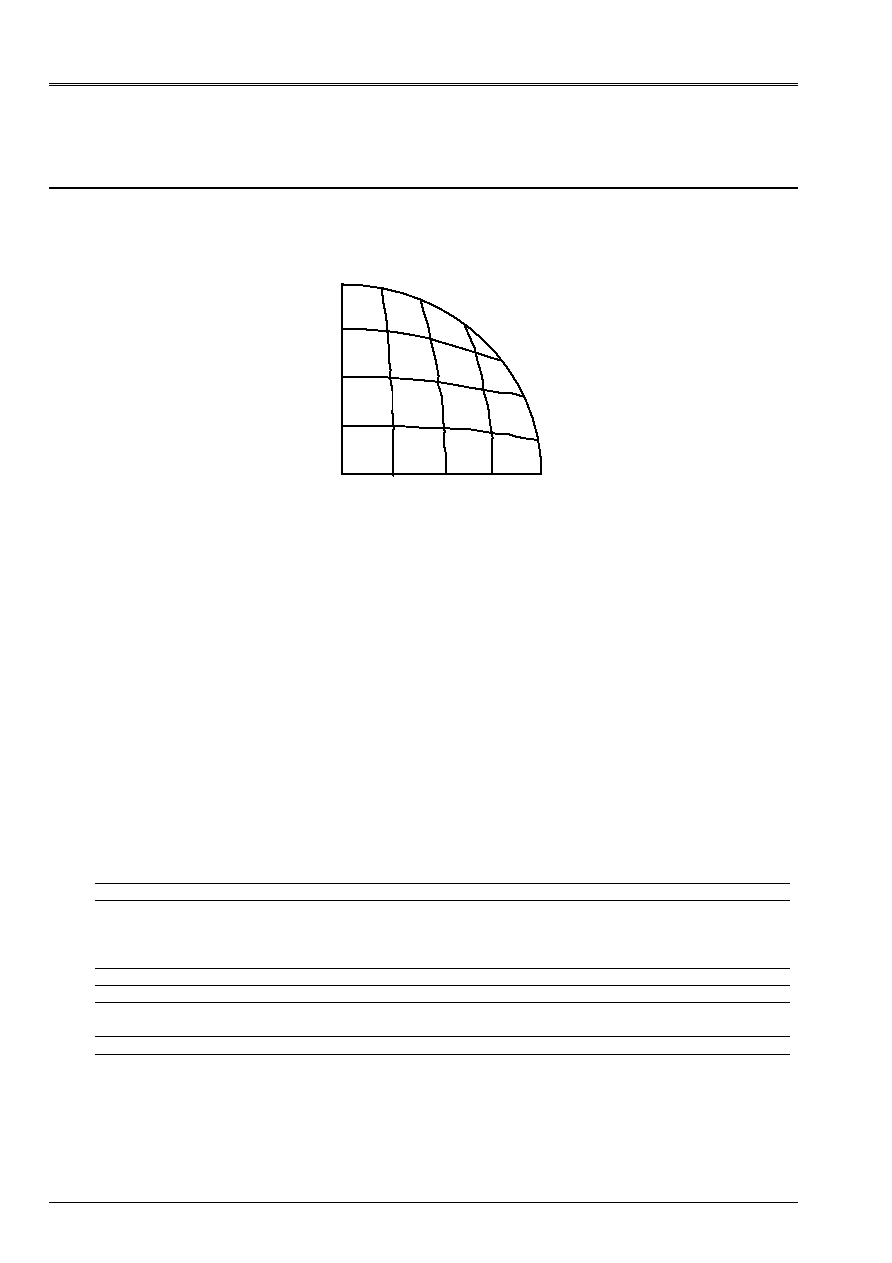
17 Modeling
I
17.1 Characteristics of modeling
Modeling: Element of
COQUE_3D
MEC3QU9H
C
E
O
D
With
B
17.1.1 Limiting conditions
in all the nodes of the arc
ABC
DX:0., DY: 0., DZ: 0.
DRX:0., DRY:0., DRZ:0.
segment] OA]
DY:0., DRX:0., DRZ:0.
segment] OC]
DX:0., DRY:0., DRZ:0.
with the node O
DX:0., DY:0., DRX:0., DRY:0., DRZ:0.
Names of the nodes:
Point 0
meshs: M1
Not A
meshs: M21
Not B
meshs: M25
Not C
meshs: M5
Not D
meshs: M11
Not E
meshs: M3
17.2 Characteristics of the mesh
A number of nodes: 96
A number of meshs and types: 25 QUAD9
17.3 Functionalities
tested
Controls
AFFE_CARA_ELEM HULL
AFFE_CHAR_MECA DDL_IMPO
GROUP_NO
FORCE_COQUE
NEAR
F3
GRAVITY
AFFE_MATERIAU ALL
“MECHANICAL” AFFE_MODELE “COQUE_3D”
ALL
CALC_CHAM_ELEM “EFFO_ELNO_DEPL”
“SIGM_ELNO_DEPL”
DEFI_MATERIAU ELAS
POST_RELEVE ACTION
OPERATION “EXTRACTION”
VALE_TEST
EPSI_TEST
Code_Aster
®
Version
7.2
Titrate:
SSLS101 Plates circular posed subjected to a uniform pressure
Date:
05/01/04
Author (S):
J.M. PROIX, P. MASSIN, D. BUI, A. LAULUSA
Key
:
V3.03.101-D
Page:
19/22
Manual of Validation
V3.03 booklet: Linear statics of the hulls and the plates
HT-66/03/008/A
18 Results of modeling I
18.1 Values
tested
Not Reference
REISSNER
Aster %
difference
O
703.40 703.41 1.42 10
3
With
0. eps -
B
0. eps -
C W
(R)
0. eps -
D
495.56 496.57 2. 10
3
E
495.56 496.57 2. 10
3
Not Reference
Aster
M
rr
M
Sm/2
M
xx
M
yy
Sm/2
O 0.20625
0.20625
0.20625
0.20842
0.20842
0.20842
To 0.
0.0875
0.04375
0.08846
0.00159
0.04502
C 0.
0.0875
0.04375
0.00067
0.08938
0.04502
D 0.15469
0.17656
0.1656
0.17743
0.15472
0.16607
E 0.15469
0.17656
0.1656
0.15459
0.17757
0.16608
Not
% difference
Relative tolerance
M
xx
M
yy
Sm/2
O 1.05
1.05
1.05 3
At 1.09
-
2.9 3
C -
2.1
2.9 5
D 0.49
0.02
0.28 1
E 0.06
0.57
0.28 1
·
with eps 10
14
and % difference on the absolute values
Note:
The test of the values is carried out automatically using the functionalities offered by
procedure
POST_RELEVE
:
·
extraction on the nodes corresponding to the points observed of the average values of
components
M
xx
and
M
yy
; these values are extracted from the field
“EFGE_ELNO_DEPL”
, and
average is calculated for all the liquid assets on the meshs which contain it
node observed,
·
calculation of the variation compared to the value of reference provided by observing the rules of
correspondence enters
M
xx
,
M
yy
and
M
rr
,
M
data page 3.
Code_Aster
®
Version
7.2
Titrate:
SSLS101 Plates circular posed subjected to a uniform pressure
Date:
05/01/04
Author (S):
J.M. PROIX, P. MASSIN, D. BUI, A. LAULUSA
Key
:
V3.03.101-D
Page:
20/22
Manual of Validation
V3.03 booklet: Linear statics of the hulls and the plates
HT-66/03/008/A
19 Modeling
J
19.1 Characteristics of modeling
Modeling: Element of
COQUE_3D
MEC3TR7H
C
E
O
D
With
B
19.1.1 Limiting conditions
in all the nodes of the arc
ABC
DX:0., DY: 0., DZ: 0.
DRX:0., DRY:0., DRZ:0.
segment] OA]
DY:0., DRX:0., DRZ:0.
segment] OC]
DX:0., DRY:0., DRZ:0.
with the node O
DX:0., DY:0., DRX:0., DRY:0., DRZ:0.
Names of the nodes:
Point 0
meshs: M1 and m2
Not A
meshs: M41
Not B
meshs: M49 and M50
Not C
meshs: M10
Not D
meshs: M21
Not E
meshs: M6
19.2 Characteristics of the mesh
A number of nodes: 121
A number of meshs and types: 50 TRIA7
19.3 Functionalities
tested
Controls
AFFE_CARA_ELEM HULL
AFFE_CHAR_MECA DDL_IMPO
GROUP_NO
FORCE_COQUE
NEAR
F3
GRAVITY
AFFE_MATERIAU ALL
“MECHANICAL” AFFE_MODELE “COQUE_3D”
ALL
CALC_CHAM_ELEM “EFFO_ELNO_DEPL”
“SIGM_ELNO_DEPL”
DEFI_MATERIAU ELAS
POST_RELEVE ACTION
OPERATION “EXTRACTION”
VALE_TEST
EPSI_TEST
Code_Aster
®
Version
7.2
Titrate:
SSLS101 Plates circular posed subjected to a uniform pressure
Date:
05/01/04
Author (S):
J.M. PROIX, P. MASSIN, D. BUI, A. LAULUSA
Key
:
V3.03.101-D
Page:
21/22
Manual of Validation
V3.03 booklet: Linear statics of the hulls and the plates
HT-66/03/008/A
20 Results of modeling J
20.1 Values
tested
Not Reference
REISSNER
Aster %
difference
O
703.40 703.19 0.03
With
0. eps -
B
0. eps -
C W
(R)
0. eps -
D
495.56 495.22 0.07
E
495.56 495.22 0.07
Not Reference
Aster
M
rr
M
Sm/2
M
xx
M
yy
Sm/2
O 0.20625
0.20625
0.20625
0.20860
0.20860
0.20860
To 0.
0.0875
0.04375
0.08619
0.00154
0.04386
C 0.
0.0875
0.04375
0.00134
0.08639
0.04386
D 0.15469
0.17656
0.1656
0.17617
0.15409
0.16513
E 0.15469
0.17656
0.1656
0.15407
0.17619
0.16513
Not
% difference
Relative tolerance
M
xx
M
yy
Sm/2
O 1.14
1.14
1.14 2
With 1.49
-
0.25 2
C -
1.27
0.25 2
D 0.22
0.39
0.28 1.
E 0.40
0.21
0.28 1.
·
with eps 10
14
and % difference on the absolute values
Note:
The test of the values is carried out automatically using the functionalities offered by
procedure
POST_RELEVE
:
·
extraction on the nodes corresponding to the points observed of the average values of
components
M
xx
and
M
yy
; these values are extracted from the field
“EFGE_ELNO_DEPL”
, and
average is calculated for all the liquid assets on the meshs which contain it
node observed,
·
calculation of the variation compared to the value of reference provided by observing the rules of
correspondence enters
M
xx
,
M
yy
and
M
rr
,
M
data page 3.
Code_Aster
®
Version
7.2
Titrate:
SSLS101 Plates circular posed subjected to a uniform pressure
Date:
05/01/04
Author (S):
J.M. PROIX, P. MASSIN, D. BUI, A. LAULUSA
Key
:
V3.03.101-D
Page:
22/22
Manual of Validation
V3.03 booklet: Linear statics of the hulls and the plates
HT-66/03/008/A
21 Summary of the results
% of the differences compared to the reference solutions
DKT
DKQ
DST
DSQ
Q4G
With
Coil-Kirchhoff
B
Coil-Kirchhoff
E
Coil-Kirchhoff
F
Reissner
G
Reissner
H
Reissner
50
nodes
76 TRIA3
170 nodes
296 TRIA3
169 nodes
147 QUAD4
170 nodes
296 TRIA3
169 nodes
147 QUAD4
169 nodes
147 QUAD4
O
()
W R
1.10 0.09 0.09
+0.12
0.11
0.15
D
()
W R
1.01 0.1 0.11
+0.08
0.13
0.20
E
()
W R
1.03 0.09 0.12
+0.09
0.13
0.20
F
()
W R
1.05 0.09 0.09
+0.07
0.15
0.21
MEC3QU9H MEC3TR7H
SHB8
I J C
96
nodes
25 QUAD9
121 nodes
50 TRIA7
338 nodes
147 HEXA8
O
()
W R
1.42
10
3
0.03 0.4
D
()
W R
2.
10
3
0.07 0.3
E
()
W R
2.
10
3
0.07 0.3
F
()
W R
-
-
0.2
DKT
DKQ
DST
DSQ
Q4G
With
Coil-Kirchhoff
B
Coil-Kirchhoff
E
Coil-Kirchhoff
F
Reissner
G
Reissner
H
Reissner
50
nodes
76 TRIA3
170 nodes
296 TRIA3
169 nodes
147 QUAD4
170 nodes
296 TRIA3
169 nodes
147 QUAD4
169 nodes
147 QUAD4
O Sm/2
1.19
+0.02
+0.07
+0.07
0.76
0.14
To Sm/2
+5.79
0.06
0.49
4.40
9.80
+17.80
B Sm/2
13.100
5.53
+1.00
9.10
7.12
+19.70
C Sm/2
+5.73
0.06
0.46
4.41
9.44
+17.90
D Sm/2
+0.20
+0.35
+0.50
+0.43
+0.49
+0.05
E Sm/2
+0.19
+0.42
+0.50
+0.49
+0.50
+0.05
F Sm/2
0.66
+0.25
0.30
+0.15
+19.00
0.33
MEC3QU9H MEC3TR7H
I J
96
nodes
25 QUAD9
121 nodes
50 TRIA7
O Sm/2
1.05
1.14
To Sm/2
2.9
0.25
B Sm/2
-
-
C Sm/2
2.9
0.25
D Sm/2
0.28
0.28
E Sm/2
0.28
0.28
F Sm/2
-
-
Concerning the efforts:
·
the value on the supported edge is unacceptable for DSQ and Q4
and to a lesser extent
for DST,
·
for DSQ, one notes in more one important error at the point F.