
Code_Aster
®
Version
7.2
Titrate:
SSLS108 - Helicoid hull under concentrated loadings
Date:
03/11/03
Author (S):
P. MASSIN, J.M. PROIX, A. LAULUSA, S. BAGUET
Key
:
V3.03.108-B
Page:
1/12
Manual of Validation
V3.03 booklet: Linear statics of the plates and hulls
HT-66/03/008/A
Organization (S):
EDF-R & D/AMA, SAMTECH, INSA-LYON
Manual of Validation
V3.03 booklet: Linear statics of the plates and hulls
Document: V3.03.108
SSLS108 - Helicoid hull under load
concentrated
Summary:
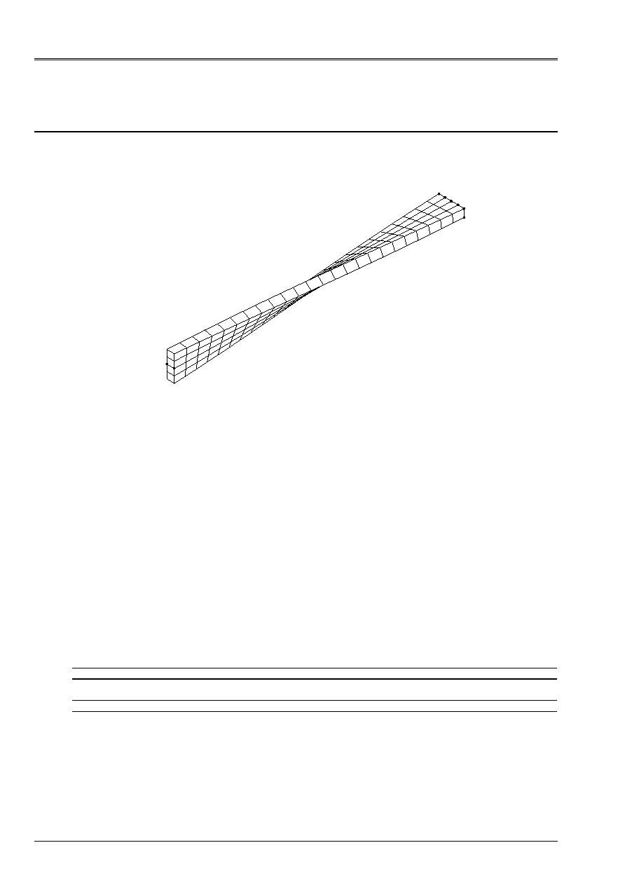
This test in linear elasticity is very severe from its geometry (left hull). Two first
modelings correspond one to the element of QUAD of modeling COQUE_3D (MEC3QU9H) and
the other with element TRI7 of modeling COQUE_3D (MEC3TR7H). The two following ones relate to
modeling SHB8.
The values of reference are computation results provided in the literature and the comparison
calculation/reference relates to displacement in a point of the structure. One notes variations compared to
reference lower than 0.15% for element MEC3QU9H and lower than 0.4% for element MEC3TR7H.
For modelings SHB8, the stupid maximum changes of 1.4% with 24 elements SHB8 (modeling C) and
0.3% with 96 SHB8 (modeling D).
Code_Aster
®
Version
7.2
Titrate:
SSLS108 - Helicoid hull under concentrated loadings
Date:
03/11/03
Author (S):
P. MASSIN, J.M. PROIX, A. LAULUSA, S. BAGUET
Key
:
V3.03.108-B
Page:
2/12
Manual of Validation
V3.03 booklet: Linear statics of the plates and hulls
HT-66/03/008/A
1
Problem of reference
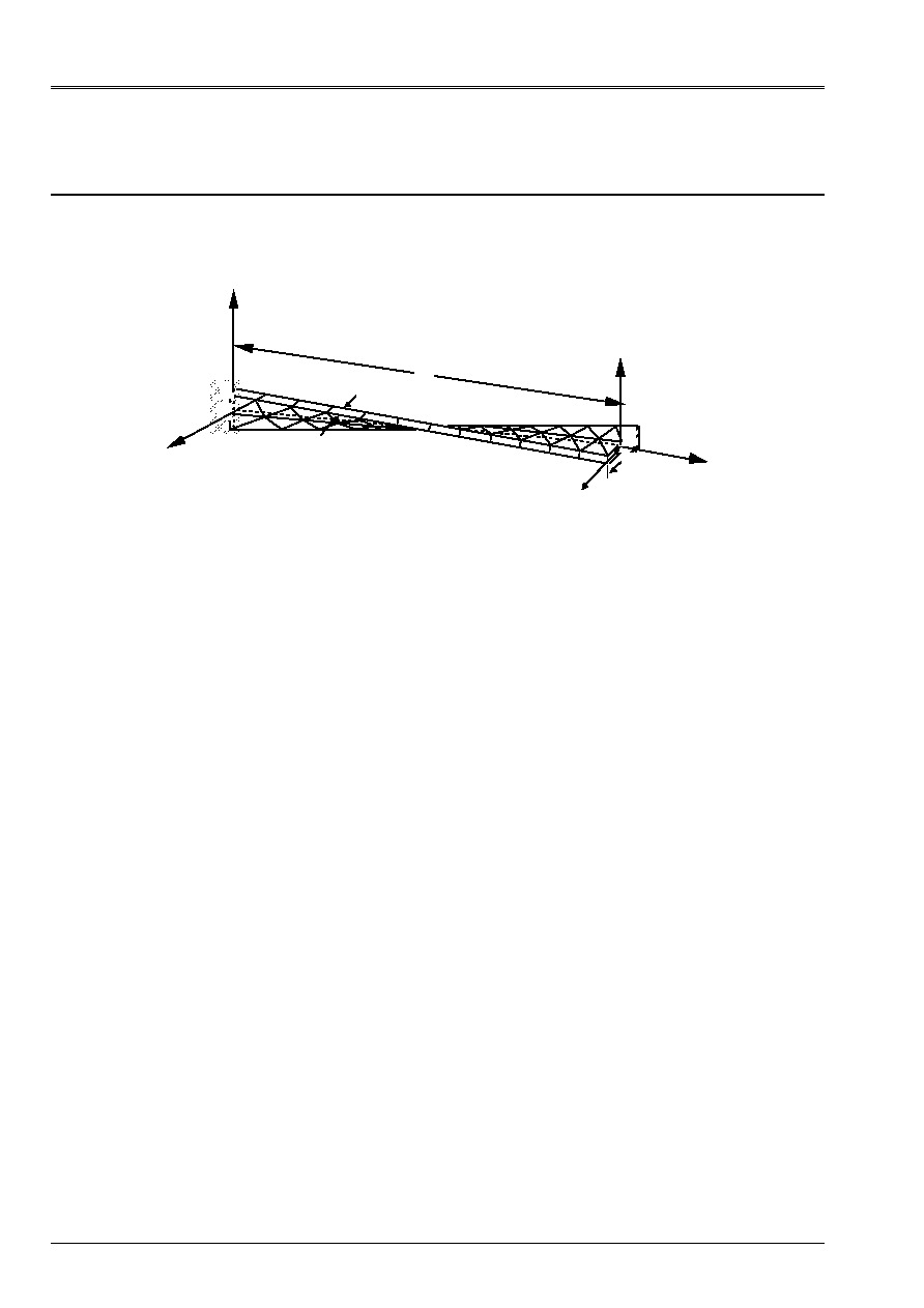
1.1 Geometry
With
F
Y
F
Z
B
X
B
C
O
Y
Z
H
L
The hull is thickness 0.32 m, length 12 m and of width 1.1 Mr.
1.2
Material properties
E = 29. 10
6
AP
= 0.22
1.3
Boundary conditions and loadings
Embedded on side OBC: U = v = W = 0,
X
=
y
=
Z
= 0
Two loading cases which corresponds to loadings concentrated at point a:
·
Force parallel with axis Z; F
Z
= 1 NR
·
Force parallel with the axis Y; F
y
= 1 NR

Code_Aster
®
Version
7.2
Titrate:
SSLS108 - Helicoid hull under concentrated loadings
Date:
03/11/03
Author (S):
P. MASSIN, J.M. PROIX, A. LAULUSA, S. BAGUET
Key
:
V3.03.108-B
Page:
3/12
Manual of Validation
V3.03 booklet: Linear statics of the plates and hulls
HT-66/03/008/A
2
Reference solution
2.1
Method of calculation used for the reference solution
Parameters of the problem and results of reference (solutions obtained by finite elements of
beam type) are given in the reference below [bib1].
2.2
Results of reference
Displacement of point A following Y
Displacement of point A following Z.
2.3 References
bibliographical
[1]
BATOZ J.L., DHATT G.: Modeling of the structures by finite elements. Volume 3 hulls,
p456-459 (1992).
Code_Aster
®
Version
7.2
Titrate:
SSLS108 - Helicoid hull under concentrated loadings
Date:
03/11/03
Author (S):
P. MASSIN, J.M. PROIX, A. LAULUSA, S. BAGUET
Key
:
V3.03.108-B
Page:
4/12
Manual of Validation
V3.03 booklet: Linear statics of the plates and hulls
HT-66/03/008/A
3 Modeling
With
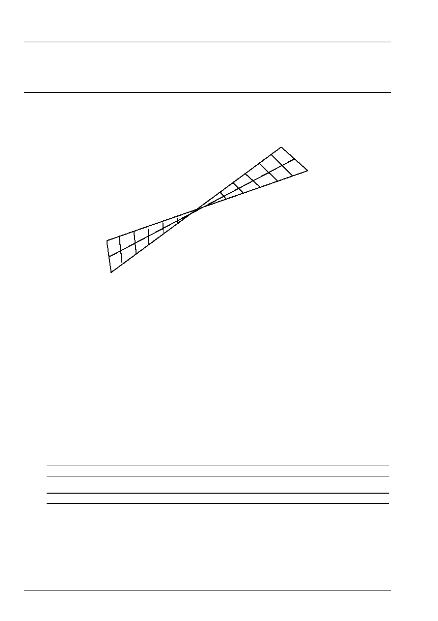
3.1
Characteristics of modeling
Element of hull 3D MEC3QU9H
B
O
C
With
Cutting:
2 according to the width, 12 according to the length
24 meshs QUAD9, thickness: H = 0.32
Names of the nodes:
Not O
N06
Not B
N01
Not C
N02
Not A
N032
3.2
Characteristics of the mesh
A number of nodes: 125
A number of meshs and types: 24 QUAD9
3.3 Functionalities
tested
Controls
AFFE_CARA_ELEM HULL
ALL
AFFE_CHAR_MECA DDL_IMPO
FORCE_NODALE
GROUP_NO
GROUP_NO
AFFE_MODELE AFFE
MODELING
:
“COQUE_3D”
DEFI_MATERIAU ELAS

Code_Aster
®
Version
7.2
Titrate:
SSLS108 - Helicoid hull under concentrated loadings
Date:
03/11/03
Author (S):
P. MASSIN, J.M. PROIX, A. LAULUSA, S. BAGUET
Key
:
V3.03.108-B
Page:
5/12
Manual of Validation
V3.03 booklet: Linear statics of the plates and hulls
HT-66/03/008/A
4
Results of modeling A
4.1 Values
tested
Case of
loads
Not
Size in unit
Reference
Aster %
difference
F
Z
= 1 NR
With
displacement V (m)
1.72 10
3
1.717
10
3
0.15
displacement W (m)
5.42 10
3
5.411
10
3
0.16
F
y
= 1 NR
With
displacement V (m)
1.75 10
3
1.750
10
3
0.0
displacement W (m)
1.72 10
3
1.717
10
3
0.15
Code_Aster
®
Version
7.2
Titrate:
SSLS108 - Helicoid hull under concentrated loadings
Date:
03/11/03
Author (S):
P. MASSIN, J.M. PROIX, A. LAULUSA, S. BAGUET
Key
:
V3.03.108-B
Page:
6/12
Manual of Validation
V3.03 booklet: Linear statics of the plates and hulls
HT-66/03/008/A
5 Modeling
B
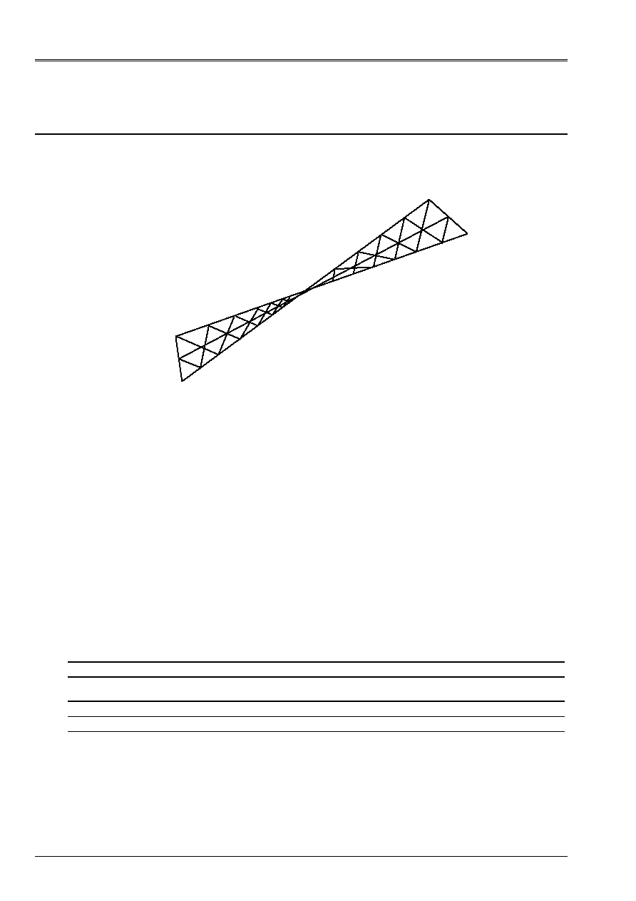
5.1
Characteristics of modeling
Element of hull MEC3TR7H
Cutting:
2 according to the width, 12 according to the length
48 meshs TRIA7, thickness: H = 0.32
Names of the nodes:
Not O
N06
Not B
N01
Not C
N02
Not A
N032
5.2
Characteristics of the mesh
A number of nodes: 173
A number of meshs and types: 48 TRIA7
5.3 Functionalities
tested
Controls
AFFE_CARA_ELEM HULL
ALL
AFFE_CHAR_MECA DDL_IMPO
FORCE_NODALE
GROUP_NO
GROUP_NO
AFFE_MATERIAU ALL
“MECHANICAL” AFFE_MODELE “COQUE_3D”
ALL
DEFI_MATERIAU ELAS

Code_Aster
®
Version
7.2
Titrate:
SSLS108 - Helicoid hull under concentrated loadings
Date:
03/11/03
Author (S):
P. MASSIN, J.M. PROIX, A. LAULUSA, S. BAGUET
Key
:
V3.03.108-B
Page:
7/12
Manual of Validation
V3.03 booklet: Linear statics of the plates and hulls
HT-66/03/008/A
6
Results of modeling B
6.1 Values
tested
Case of
loads
Not
Size in unit
Reference
Aster %
difference
F
Z
= 1 NR
With
displacement V (m)
1.72 10
3
1.714
10
3
0.34
displacement W (m)
5.42 10
3
5.399
10
3
0.38
F
y
= 1 NR
With
displacement V (m)
1.75 10
3
1.746
10
3
0.23
displacement W (m)
1.72 10
3
1.714
10
3
0.34
Code_Aster
®
Version
7.2
Titrate:
SSLS108 - Helicoid hull under concentrated loadings
Date:
03/11/03
Author (S):
P. MASSIN, J.M. PROIX, A. LAULUSA, S. BAGUET
Key
:
V3.03.108-B
Page:
8/12
Manual of Validation
V3.03 booklet: Linear statics of the plates and hulls
HT-66/03/008/A
7 Modeling
C
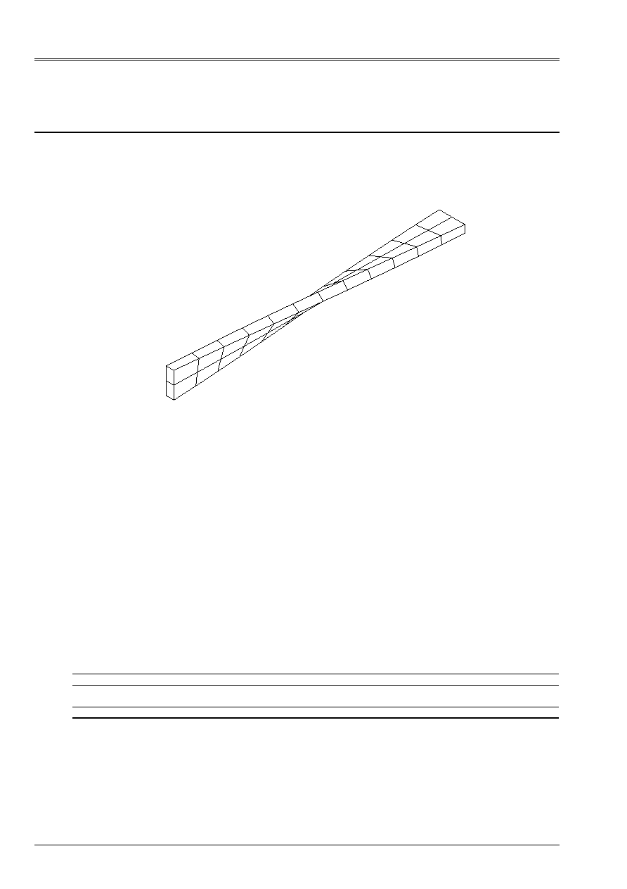
7.1
Characteristics of modeling
MASSIVE element of hull SHB8
O1 C1
C2
B1
A2
A1
Cutting:
2 according to the width, 12 according to the length
24 meshs SHB8, thickness: H = 0.32
Names of the nodes:
Not O1
N03
Not O2
N05
Not B1
N04
Not B2
N06
Not C1
N01
Not C2
N02
Not A1
N78
Not A2
N75
7.2
Characteristics of the mesh
A number of nodes: 78
A number of meshs and types: 24 SHB8
7.3 Functionalities
tested
Controls
MODI_MAILLAGE ORIE_SHB8
GROUP_MA
ALL
AFFE_CHAR_MECA DDL_IMPO
FORCE_NODALE
GROUP_NO
GROUP_NO
AFFE_MODELE AFFE
MODELING
:
SHB8
DEFI_MATERIAU ELAS

Code_Aster
®
Version
7.2
Titrate:
SSLS108 - Helicoid hull under concentrated loadings
Date:
03/11/03
Author (S):
P. MASSIN, J.M. PROIX, A. LAULUSA, S. BAGUET
Key
:
V3.03.108-B
Page:
9/12
Manual of Validation
V3.03 booklet: Linear statics of the plates and hulls
HT-66/03/008/A
8
Results of modeling C
8.1 Values
tested
Case of
loads
Not
Size in unit
Reference
Aster
% difference
F
Z
= 1 NR
A1 and A2
displacement V (m)
1.72 10
3
1.717 10
3
0.16
displacement W (m)
5.42 10
3
5.408 10
3
0.21
F
y
= 1 NR
A1 and A2
displacement V (m)
1.75 10
3
1.726 10
3
1.36
displacement W (m)
1.72 10
3
1.717 10
3
0.16
8.2 Remarks
A modeling 3D on the same mesh (meshs HEXA8) revealed a blocking: results
are very far away from the reference. For example, in the case of load 1, one obtains:
Not
Size in unit
Reference
Aster
A1 and A2
displacement V (m)
displacement W (m)
1.72 10
3
5.42 10
3
7.5 10
4
5.408 10
3
This blocking does not appear any more with quadratic meshs HEXA20, since one obtains then:
Not
Size in unit
Reference
Aster
A1 and A2
displacement V (m)
displacement W (m)
1.72 10
3
5.42 10
3
1.729 10
3
5.43 10
3
Modeling SHB8 makes it possible to avoid any numerical blocking, at a cost (in time CPU) similar to
that of a mesh HEXA8.
Code_Aster
®
Version
7.2
Titrate:
SSLS108 - Helicoid hull under concentrated loadings
Date:
03/11/03
Author (S):
P. MASSIN, J.M. PROIX, A. LAULUSA, S. BAGUET
Key
:
V3.03.108-B
Page:
10/12
Manual of Validation
V3.03 booklet: Linear statics of the plates and hulls
HT-66/03/008/A
9 Modeling
D
9.1
Characteristics of modeling
MASSIVE element of hull SHB8
A2
A1
C1
E1
O1
D1
B1
C2
Cutting:
4 according to the width, 24 according to the length
96 meshs SHB8, thickness: H = 0.32
Names of the nodes:
Not O1
N245
Not O2
N249
Not B1
N224
Not B2
N226
Not C1
N239
Not C2
N241
Not D1
N236
Not D2
N238
Not E1
N250
Not E2
N246
Not A1
N05
Not A2
N06
9.2
Characteristics of the mesh
A number of nodes: 250
A number of meshs and types: 96 SHB8
9.3 Functionalities
tested
Controls
MODI_MAILLAGE ORIE_SHB8
GROUP_MA
ALL
AFFE_CHAR_MECA DDL_IMPO
FORCE_NODALE
GROUP_NO
GROUP_NO
AFFE_MODELE AFFE
MODELING
:
SHB8
DEFI_MATERIAU ELAS

Code_Aster
®
Version
7.2
Titrate:
SSLS108 - Helicoid hull under concentrated loadings
Date:
03/11/03
Author (S):
P. MASSIN, J.M. PROIX, A. LAULUSA, S. BAGUET
Key
:
V3.03.108-B
Page:
11/12
Manual of Validation
V3.03 booklet: Linear statics of the plates and hulls
HT-66/03/008/A
10 Results of modeling D
10.1 Values
tested
Case of
loads
Not
Size in unit
Reference
Aster
% difference
F
Z
= 1 NR
A1 and A2
displacement V (m)
1.72 10
3
1.718 10
3
0.09
displacement W (m)
5.42 10
3
5.41 10
3
0.18
F
y
= 1 NR
A1 and A2
displacement V (m)
1.75 10
3
1.744 10
3
0.33
displacement W (m)
1.72 10
3
1.718 10
3
0.09
10.2 Remarks
A modeling 3D on the same mesh (meshs HEXA8) revealed a blocking: even with
a mesh with 96 elements. The results remain very far away from the reference. For example, for
loading case 1, one obtains:
Not
Size in unit
Reference
Aster
A1 and A2
displacement V (m)
displacement W (m)
1.72 10
3
5.42 10
3
2.49 10
4
1.12 10
3
This blocking does not appear any more with quadratic meshs HEXA20, since one obtains then:
Not
Size in unit
Reference
Aster
A1 and A2
displacement V (m)
displacement W (m)
1.72 10
3
5.42 10
3
1.735 10
3
5.438 10
3
With HEXA20, convergence is much better. Modeling SHB8 makes it possible to avoid all
numerical blocking, at a cost (in time CPU) similar to that of a mesh HEXA8.

Code_Aster
®
Version
7.2
Titrate:
SSLS108 - Helicoid hull under concentrated loadings
Date:
03/11/03
Author (S):
P. MASSIN, J.M. PROIX, A. LAULUSA, S. BAGUET
Key
:
V3.03.108-B
Page:
12/12
Manual of Validation
V3.03 booklet: Linear statics of the plates and hulls
HT-66/03/008/A
11 Summary of the results
This test is very severe because of geometry of the hull which is left.
Good solutions are obtained for four modelings.