Code_Aster
®
Version
5.0
Titrate:
SSLS109 Plaque in traction made up of three tablecloths of reinforcements
Date
:
21/03/02
Author (S):
C. CHAVANT, O. MERABET, Mr. DJERROUD
Key
:
V3.03.109-A
Page:
1/8
Manual of Validation
V3.03 booklet: Linear statics of the plates and hulls
HT-66/02/001/A
Organization (S):
EDF/AMA, INSA-Lyon
Manual of Validation
V3.03 booklet: Linear statics of the plates and hulls
V3.03.109 document
SSLS109 - Plate in traction made up of three
tablecloths of reinforcements (Model ROASTS)
Summary
This test quasi-static 2D forced plane enters within the framework of the validation of the finite elements in elasticity
linear. A plate made up of three tablecloths of reinforcements offset compared to the average layer is
subjected to a uniaxial traction. The orientations of the reinforcements and the mechanical characteristics are
different for the three tablecloths.
The main interest of this test is to validate in linear elasticity the model “ROASTS” which is in fact an element
of thin section (DKT) with a offsetting compared to the average layer.
The results provided by the model “ROASTS” (modeling B) are identical to those obtained by
modeling “DEFI_COQU_MULT” of Code_Aster (modeling A).
Code_Aster
®
Version
5.0
Titrate:
SSLS109 Plaque in traction made up of three tablecloths of reinforcements
Date
:
21/03/02
Author (S):
C. CHAVANT, O. MERABET, Mr. DJERROUD
Key
:
V3.03.109-A
Page:
2/8
Manual of Validation
V3.03 booklet: Linear statics of the plates and hulls
HT-66/02/001/A
1
Problem of reference
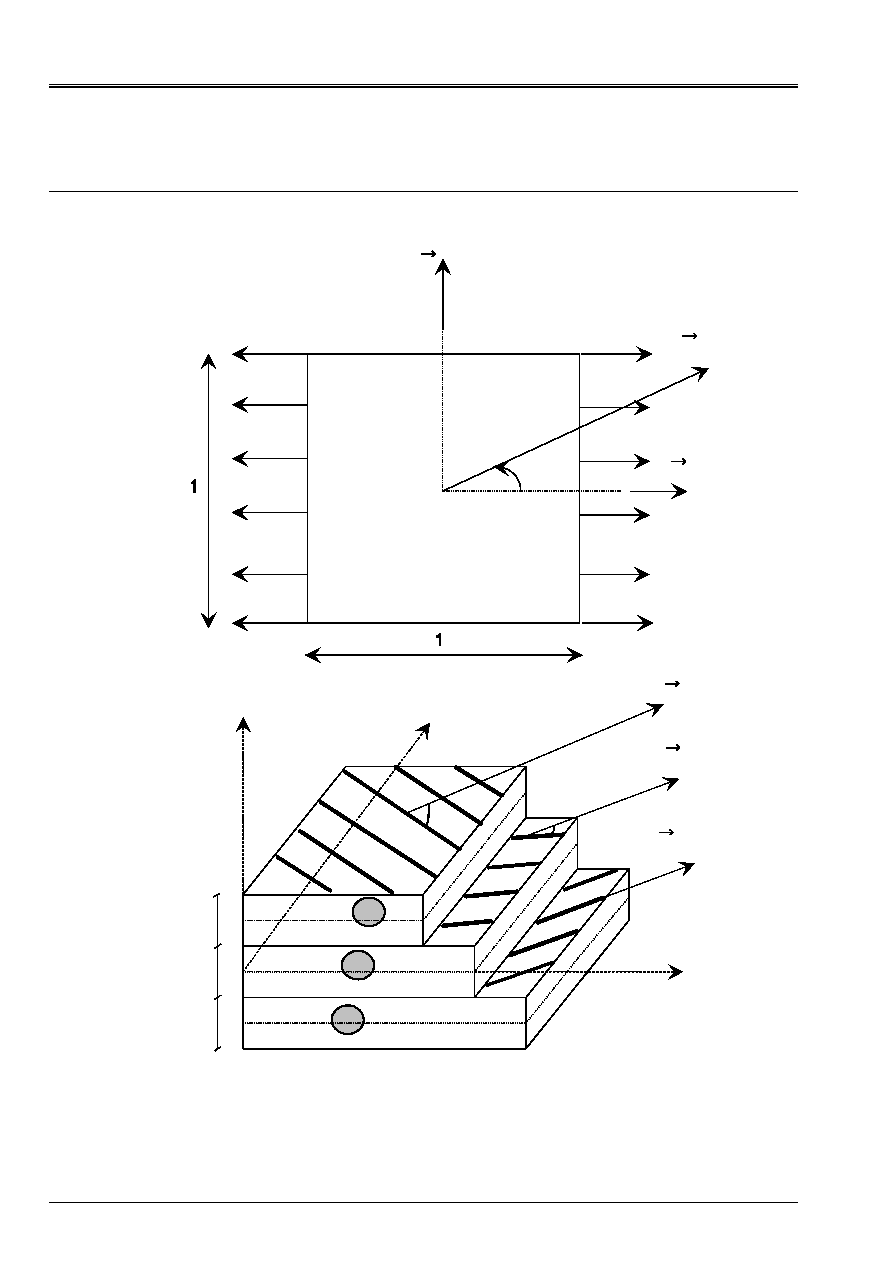
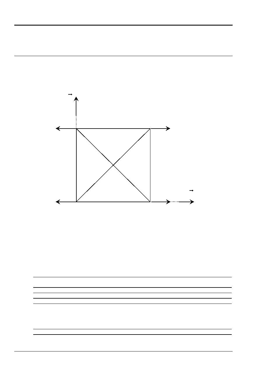
1.1 Geometry
Y
X
X
ref.
30°
NO3
NO4
NO1
NO2
1
2
3
X
Y
Z
E
E
E
X
ref.
X
ref.
- 20°
- 75°
X
ref.
Code_Aster
®
Version
5.0
Titrate:
SSLS109 Plaque in traction made up of three tablecloths of reinforcements
Date
:
21/03/02
Author (S):
C. CHAVANT, O. MERABET, Mr. DJERROUD
Key
:
V3.03.109-A
Page:
3/8
Manual of Validation
V3.03 booklet: Linear statics of the plates and hulls
HT-66/02/001/A
1.2
Properties of materials
Solid 1
1
1
=
E
;
7
1
10
-
=
G
;
0
1
=
;
1
1
1
=
=
T
L
; offsetting = +0,01; épaisseur=0,01
Solid 2
2
2
=
E
;
7
2
10
-
=
G
;
0
2
=
;
1
2
2
=
=
T
L
; offsetting = 0,00; épaisseur= 0,01
Solid 3
3
3
=
E
;
7
3
10
-
=
G
;
0
3
=
;
1
3
3
=
=
T
L
; offsetting = - 0,01; épaisseur= 0,01
1.3
Boundary conditions and loadings
Embedded side NO1-NO4.
One imposes a tensile load on side NO2-NO3: FX = 2
2
Reference solution
2.1 Solution
formal
Model DEFI_COQU_MULT of Code_Aster (modeling A) makes it possible to validate the model
“GRID” proposed (modeling B).
2.2
Numerical values of reference
Values of:
U, v, W,
X
and
y
with node NO2,
membrane deformation:
xy
yy
xx
,
,
in solid 1 calculated with node NO2,
variation of curvature:
xy
yy
xx
,
,
in solid 1 calculated with node NO2,
stresses 3D:
xy
zz
yy
xx
,
,
,
in solid 1 calculated with node NO2.
Code_Aster
®
Version
5.0
Titrate:
SSLS109 Plaque in traction made up of three tablecloths of reinforcements
Date
:
21/03/02
Author (S):
C. CHAVANT, O. MERABET, Mr. DJERROUD
Key
:
V3.03.109-A
Page:
4/8
Manual of Validation
V3.03 booklet: Linear statics of the plates and hulls
HT-66/02/001/A
3 Modeling
With
3.1
Characteristics of modeling
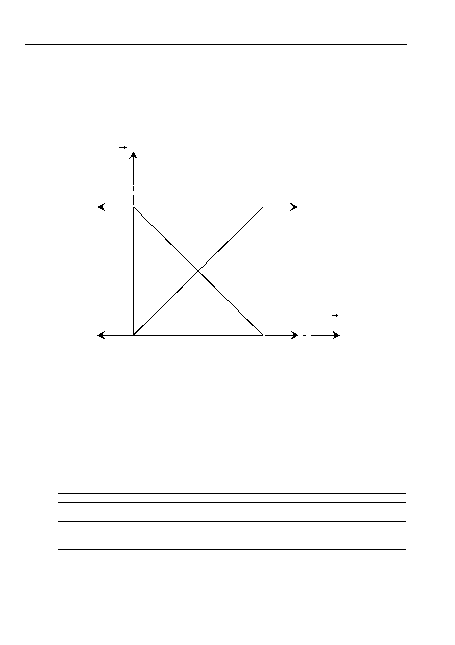
The test-tube is with a grid with four elements “DKT”
1
1
1
1
NO1
NO2
NO3
NO4
NO5
X
Y
Mesh:
A number of nodes: 5
A number of meshs and type: 4 meshs TRIA3
The mesh is symmetrical in order to avoid the parasitic modes of deformations.
3.2
Stages of calculation and functionalities tested
The main stages of calculation correspond to the functionalities which one wishes to validate:
Controls
AFFE_MODELE AFFE MODELING
“DKT”
AFFE_CARA_ELEM HULL
DEFI_MATERIAU ELAS_ORTH
DEFI_COQU_MULT SLEEP
MECA_STATIQUE
CALC_ELEM
CALC_NO
RECU_CHAMP

Code_Aster
®
Version
5.0
Titrate:
SSLS109 Plaque in traction made up of three tablecloths of reinforcements
Date
:
21/03/02
Author (S):
C. CHAVANT, O. MERABET, Mr. DJERROUD
Key
:
V3.03.109-A
Page:
5/8
Manual of Validation
V3.03 booklet: Linear statics of the plates and hulls
HT-66/02/001/A
4
Results of modeling A
Variables
DEFI_COQU_MULT
(modeling A)
Displacements node NO2
U 81.9373
v 18.6398
W 2098.66
X
1239.88
y
3820.42
Deformations node NO2
(Solid 1)
xx
32.9433
yy
2.33011
xy
34.3522
zz
0
Stresses node NO2
(Solid 1)
xx
42.7252
yy
63.0951
xy
5.88029
zz
0
Curvatures node NO2
(Solids 1, 2 and 3)
xx
531.043
yy
2035.19
xy
2058.44
4.1 Remarks
The results presented are given in the reference mark of reference
)
,
(
ref.
ref.
Y
X
R
R
forming an angle of 30°
compared to
)
,
(Y
X R
R
, concerning the deformations, stresses and curvatures.
Code_Aster
®
Version
5.0
Titrate:
SSLS109 Plaque in traction made up of three tablecloths of reinforcements
Date
:
21/03/02
Author (S):
C. CHAVANT, O. MERABET, Mr. DJERROUD
Key
:
V3.03.109-A
Page:
6/8
Manual of Validation
V3.03 booklet: Linear statics of the plates and hulls
HT-66/02/001/A
5
Modeling B (GRID)
5.1
Characteristics of modeling
The test-tube is with a grid with 12 elements “ROASTS” (4 elements by tablecloth of reinforcements) to three
nodes (thin section: formulation DKT with offsetting compared to the datum-line).
nodes are common to each tablecloth.
1
1
1
1
NO1
NO2
NO3
NO4
NO5
X
Y
Mesh:
A number of nodes: 5
A number of meshs and type: 3x4 meshs TRIA3
The mesh is symmetrical in order to avoid the parasitic modes of deformations.
5.2
Stages of calculation and functionalities tested
The main stages of calculation correspond to the functionalities which one wishes to validate:
Controls
AFFE_MODELE AFFE
MODELING “ROASTS”
PHENOMENON
“MECHANICAL”
DEFI_MATERIAU ELAS
AFFE_CARA_ELEM ROASTS
MECA_STATIQUE
CALC_ELEM OPTION
EPSI_ELNO_DEPL
SIGM_ELNO_DEPL
DEGE_ELNO_DEPL
EFGE_ELNO_DEPL
SIEF_ELGA_DEPL
CALC_NO OPTION
FORC_NODA
RECU_CHAMP
Code_Aster
®
Version
5.0
Titrate:
SSLS109 Plaque in traction made up of three tablecloths of reinforcements
Date
:
21/03/02
Author (S):
C. CHAVANT, O. MERABET, Mr. DJERROUD
Key
:
V3.03.109-A
Page:
7/8
Manual of Validation
V3.03 booklet: Linear statics of the plates and hulls
HT-66/02/001/A
6
Results of modeling B
Variables
Modeling A
Modeling B
% difference
Displacements node NO2
U 81.9373
81.9373
0
v 18.6398
18.6398
0
W 2098.66
2098.66
0
X
1239.88 1239.88 0
y
3820.42 3820.42 0
Deformations node NO2
(Solid 1)
xx
32.9433 32.9433 0
yy
2.33011 2.33011 0
xy
34.3522 34.3522 0
zz
0 0
0
Stresses node NO2
(Solid 1)
xx
42.7252 42.7252 0
yy
63.0951 63.0951 0
xy
5.88029 5.88029 0
zz
0 0
0
Curvatures node NO2
(Solids 1, 2 and 3)
xx
531.043 531.043 0
yy
2035.19 2035.19 0
xy
2058.44 2058.44 0
6.1 Remarks
The results presented are given in the reference mark of reference
)
,
(
ref.
ref.
Y
X
R
R
forming an angle of 30°
compared to
)
,
(Y
X R
R
, concerning the deformations, stresses and curvatures
.

Code_Aster
®
Version
5.0
Titrate:
SSLS109 Plaque in traction made up of three tablecloths of reinforcements
Date
:
21/03/02
Author (S):
C. CHAVANT, O. MERABET, Mr. DJERROUD
Key
:
V3.03.109-A
Page:
8/8
Manual of Validation
V3.03 booklet: Linear statics of the plates and hulls
HT-66/02/001/A
7
Summary of the results and remarks general
The results of modeling A are identical to those of modeling B.