
Code_Aster
®
Version
5.0
Titrate:
SSLS111 - Offsetting of simple plate
Date:
19/09/02
Author (S):
P. MASSIN, J.M. PROIX
Key
:
V3.03.111-A
Page:
1/10
Manual of Validation
V3.03 booklet: Linear statics of the plates and hulls
HT-66/02/001/A
Organization (S):
EDF/AMA
Manual of Validation
V3.03 booklet: Linear statics of the plates and hulls
Document: V3.03.111
SSLS111 - Simple Excentremement of plate
Summary:
This test makes it possible to validate the offsetting of the simple plates (i.e it acts neither of multi-layer, nor of one
homogenized behavior).
The reference is given by a first resolution where one modelizes double-layered made up of 2 materials.
The validation is done in the second calculation where one modelizes the 2 layers of the preceding model by 2 plates
offset compared to the average plan of the first calculation.
Three modelings are used: DKT, DST (meshs QUAD4) DST (meshs TRIA3).
Code_Aster
®
Version
5.0
Titrate:
SSLS111 - Simple offsetting of plate
Date:
19/09/02
Author (S):
P. MASSIN, J.M. PROIX
Key
:
V3.03.111-A
Page:
2/10
Manual of Validation
V3.03 booklet: Linear statics of the plates and hulls
HT-66/02/001/A
1
Problem of reference
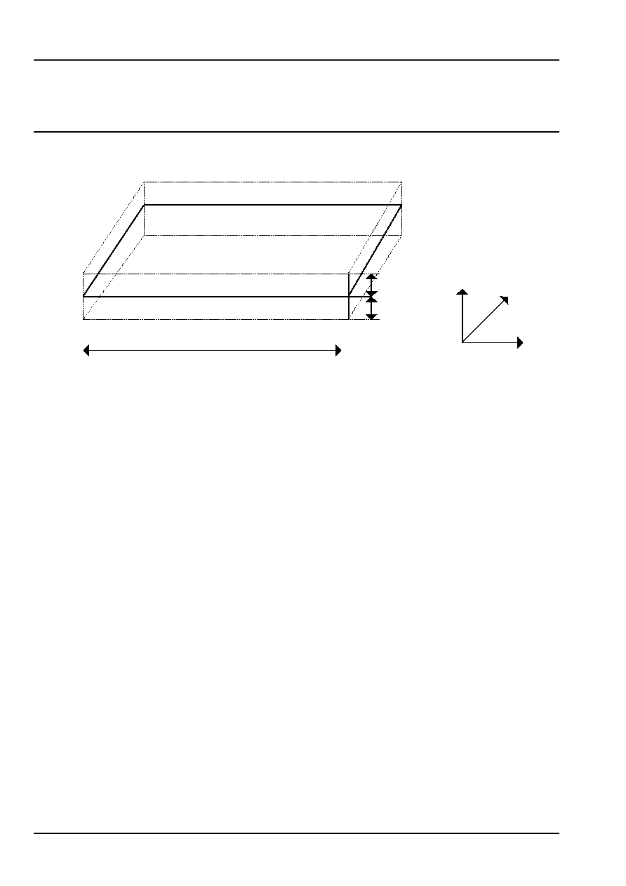
1.1 Geometry
A3
5 subdivisions
Z y
GRN011
0.2
m
A2
0.2
m
A1
10
subdivisions
X
The co-ordinates of the points are:
A1 (0,0,0)
A3 (10,5,0)
A2 (10,0,0)
A4 (0,5,0)
1.2
Material properties
The material is double-layered.
The material constituting the first layer is orthotropic and is characterized by the data
following:
EL = 20000.MPa
AND = 20000.MPa
VLT = 0.3
GLT = 2000.MPa.
The material constituting the second layer is also orthotropic and is characterized by the data
following:
EL = 15000.MPa
AND = 15000.MPa
VLT = 0.3
GLT = 1500.MPa
1.3
Boundary conditions and loadings
The A1 node is embedded:
dx = 0.
Dy = 0.
dz = 0.
dRx = 0.
DRy = 0.
DRz=0.
The A2 node is locked according to following ddls:
dx = 0.
Dy = 0.

Code_Aster
®
Version
5.0
Titrate:
SSLS111 - Simple offsetting of plate
Date:
19/09/02
Author (S):
P. MASSIN, J.M. PROIX
Key
:
V3.03.111-A
Page:
3/10
Manual of Validation
V3.03 booklet: Linear statics of the plates and hulls
HT-66/02/001/A
One applies a nodal force Fz = 1000 to the A3 node.
In addition, one applies to the meshs M1, m2 and m3 (see drawing) the loading distributed (key word
Force_coque) according to:
Fx = 200 NR/m
2
, Fy = 500 NR/m
2
, Fz = 500 NR/m
2
, MX = 100 NR/m, My = 40 NR/m
in the plan of the mesh.
2
Reference solution
2.1
Method of calculation used for the reference solution
Calculation with double-layered material is used as reference. Nonregression of the results obtained for it
the first calculation is checked.
2.2
Results of reference
They are consisted of the values of the field of displacement DX, DY, DZ, DRX, DRY at the point A3 (node
N1 for ASTER) and at the point of co-ordinates (9,2,0).
One compares also the efforts with the A1 point.
In addition, the 4 smaller frequencies of the structure are calculated.
2.3
Uncertainty on the solution
Null since it is about the same calculation carried out by two different channels.
Code_Aster
®
Version
5.0
Titrate:
SSLS111 - Simple offsetting of plate
Date:
19/09/02
Author (S):
P. MASSIN, J.M. PROIX
Key
:
V3.03.111-A
Page:
4/10
Manual of Validation
V3.03 booklet: Linear statics of the plates and hulls
HT-66/02/001/A
3 Modeling
With
3.1
Characteristics of modeling
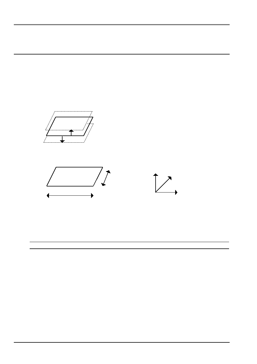
The model consists of 2 plates corresponding to the average plan of the 2 layers of the model of
reference.
To represent these 2 plates, one leaves the mesh of the average plan of double-layered which one offsets
distances 0.1 and 0.1.
PLAQ1
PLAQ 2
+ 0.1
-
0.1
3.2
Characteristics of the mesh
Z
y
5
10
X
The mesh is regular. There are 10 subdivisions according to X and 5 subdivisions according to y; that is to say on the whole 50 meshs
DKQ (quad4) and 66 nodes.
3.3 Functionalities
tested
Order
Key word factor key Word
AFFE_CARA_ELEM
Offsetting
AFFE_CHAR_MECA
Force_coque
PLAN
The elements used are elements of
plate DKQ.

Code_Aster
®
Version
5.0
Titrate:
SSLS111 - Simple offsetting of plate
Date:
19/09/02
Author (S):
P. MASSIN, J.M. PROIX
Key
:
V3.03.111-A
Page:
5/10
Manual of Validation
V3.03 booklet: Linear statics of the plates and hulls
HT-66/02/001/A
4
Results of modeling A
4.1 Values
tested
Identification Reference
Aster %
Difference
DX (N1)
7.9818
7.9818
0
DY (N1)
1.1477
1.1477
0
DZ (N1)
6330
6330
0
DRX (N1)
454.433
454.433
0
DRY (N1)
566.451
566.451
0
DX (N10)
4.5814
4.5814
0
DY (N10)
1.8758
1.8758
0
DZ (N10)
4466
4466
0
DRX (N10)
430.09
430.09
0
DRY (N10)
512.163
512.163
0
Frequency 1
Er
mode
9.5393.10
4
9.5393.10
4
0
Frequency 2
ème
mode
3.7115.10
3
3.7115.10
3
0
Frequency 3
ème
mode
8.2208.10
3
8.2208.10
3
0
Frequency 4
ème
mode
1.6837.10
2
1.6837.10
- 2
0
NXX
2.2024.10
4
2.2024.10
4
0
NYY
2.4402.10
3
2.4402.10
3
0
NXY
1.0581.10
3
1.0581.10
3
0
MXX
4.1733.10
4
4.1733.10
4
0
MYY
1.8444.10
4
1.8444.10
4
0
MXY
6.3333.10
3
6.3333.10
3
0
QX
3.193.10
4
3.193.10
4
0
QY
1.4346.10
4
1.4346.10
4
0
Code_Aster
®
Version
5.0
Titrate:
SSLS111 - Simple offsetting of plate
Date:
19/09/02
Author (S):
P. MASSIN, J.M. PROIX
Key
:
V3.03.111-A
Page:
6/10
Manual of Validation
V3.03 booklet: Linear statics of the plates and hulls
HT-66/02/001/A
5 Modeling
B
5.1
Characteristic of modeling
The model is the same one as that of modeling A, with this close that instead of having elements of
plate DKQ, one has elements DSQ.
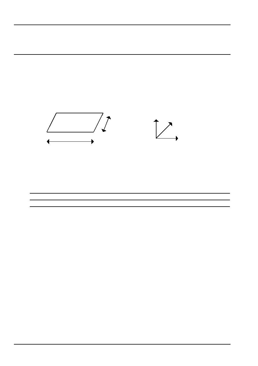
5.2
Characteristic of the mesh
Z
y
5
10
X
The mesh is regular. There are 10 subdivisions according to X and 5 subdivisions according to y; that is to say on the whole 50 meshs
DSQ and 66 nodes.
5.3 Functionalities
tested
Order
Key word factor key Word
AFFE_CARA_ELEM
Offsetting
AFFE_CHAR_MECA
Force_coque
PLAN
AFFE_MODELE
AFFE
MODELING = DST

Code_Aster
®
Version
5.0
Titrate:
SSLS111 - Simple offsetting of plate
Date:
19/09/02
Author (S):
P. MASSIN, J.M. PROIX
Key
:
V3.03.111-A
Page:
7/10
Manual of Validation
V3.03 booklet: Linear statics of the plates and hulls
HT-66/02/001/A
6
Result of modeling B
6.1 Values
tested
Identification Reference
Aster %
Difference
DEPL DX N1
7.98940E06
8.01344E06
0.301
DEPL DY N1
1.17388E06
1.19166E06
1.514
DEPL DZ N1
6.35573E03
6.37537E03
0.309
DEPL DRX N1
4.42621E04
4.39613E04
0.679
DEPL DRY N1
5.72702E04
5.75565E04
0.500
DEPL DX N10
4.62813E06
4.65034E06
0.480
DEPL DY N10
1.88945E06
1.90341E06
0.739
DEPL DZ N10
4.52107E03
4.54691E03
0.572
DEPL DRX N10
4.17874E04
4.14602E04
0.783
DEPL DRY N10
5.19527E04
5.22722E04
0.615
EFGE NXX N60
1.62953E+04
1.53979E+04
5.507
EFGE NYY N60
4.50035E+03
5.11922E+03
13.752
EFGE NXY N60
9.91495E+02
9.30980E+02
6.103
EFGE MXX N60
3.63645E+04
3.56107E+04
2.073
EFGE MYY N60
1.59599E+04
1.56220E+04
2.118
EFGE MXY N60
6.31716E+03
6.32614E+03
0.142
EFGE QX N60
2.07352E+04
1.90500E+04
8.127
EFGE QY N60
1.04743E+04
1.01187E+04
3.395
MODE 1
9.50214E-01
9.48127E-01
0.220
MODE 2
3.61805E+00
3.58389E+00
0.944
MODE 3
8.16228E+00
8.13462E+00
0.339
MODE 4
1.65440E+01
1.64359E+01
0.653
6.2 Remarks
There is a difference (not explained) on this modeling between the value of reference (double-layered) and
two offset plates.
Code_Aster
®
Version
5.0
Titrate:
SSLS111 - Simple offsetting of plate
Date:
19/09/02
Author (S):
P. MASSIN, J.M. PROIX
Key
:
V3.03.111-A
Page:
8/10
Manual of Validation
V3.03 booklet: Linear statics of the plates and hulls
HT-66/02/001/A
7 Modeling
C
7.1
Characteristics of modeling
The model is the same one as that of modeling A, with this close that instead of having elements of
plate DKQ, one has DST elements. (DST Modeling with meshs TRIA3).
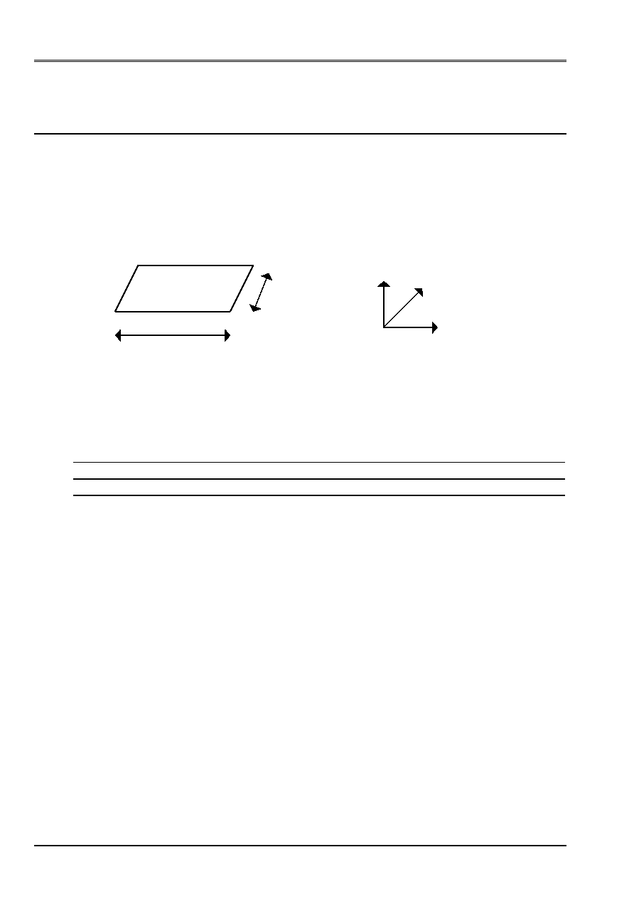
7.2
Characteristics of the mesh
Z
y
5
10
X
The mesh is regular. There are 10 subdivisions according to X and 5 subdivisions according to y; that is to say on the whole 100
DST meshs and 66 nodes.
7.3 Functionalities
tested
Order
Key word factor key Word
AFFE_CARA_ELEM
Offsetting
AFFE_CHAR_MECA
Force_coque
PLAN
AFFE_MODELE
AFFE
MODELING = DST

Code_Aster
®
Version
5.0
Titrate:
SSLS111 - Simple offsetting of plate
Date:
19/09/02
Author (S):
P. MASSIN, J.M. PROIX
Key
:
V3.03.111-A
Page:
9/10
Manual of Validation
V3.03 booklet: Linear statics of the plates and hulls
HT-66/02/001/A
8
Result of modeling C
8.1 Values
tested
Identification Reference
Aster %
Difference
DEPL DX N66
6.49678E06
6.50205E06
0.081
DEPL DY N66
6.08932E07
6.10332E07
0.230
DEPL DZ N66
5.33844E03
5.36043E03
0.412
DEPL DRX N66
4.29182E04
4.29587E04
0.095
DEPL DRY N66
4.75601E04
4.77482E04
0.395
DEPL DX N53
3.58293E06
3.58709E06
0.116
DEPL DY N53
1.18788E06
1.19013E06
0.190
DEPL DZ N53
3.63885E03
3.65793E03
0.524
DEPL DRX N53
4.05175E04
4.05324E04
0.037
DEPL DRY N53
4.23116E04
4.25311E04
0.519
EFGE NXX N6
1.70005E+04
1.68443E+04
0.918
EFGE NYY N6
1.14438E+04
1.12660E+04
1.554
EFGE NXY N6
3.53598E+03
3.57111E+03
0.993
EFGE MXX N6
2.14585E+04
2.13070E+04
0.706
EFGE MYY N6
1.53094E+04
1.51378E+04
1.121
EFGE MXY N6
5.71331E+03
5.76258E+03
0.862
EFGE QX N6
3.03380E+03
2.81593E+03
7.181
EFGE QY N6
1.76436E+03
1.78725E+03
1.297
MODE 1
1.01181E+00
1.00910E+00
0.268
MODE 2
4.27003E+00
4.26070E+00
0.218
MODE 3
8.39151E+00
8.36517E+00
0.314
MODE 4
1.72305E+01
1.71358E+01
0.549
8.2 Remarks
As for modeling B, one notes a difference between the solution obtained for a hull
double-layered and that resulting from two offset full-course hulls, without it being possible at the time
drafting of the test to determine from which the variation comes.

Code_Aster
®
Version
5.0
Titrate:
SSLS111 - Simple offsetting of plate
Date:
19/09/02
Author (S):
P. MASSIN, J.M. PROIX
Key
:
V3.03.111-A
Page:
10/10
Manual of Validation
V3.03 booklet: Linear statics of the plates and hulls
HT-66/02/001/A
9
Summary of the results
With regard to modeling A (DKT) results obtained with two full-course hulls
offset coincide perfectly with those obtained by a double-layered hull, as well in terms
displacements, that generalized efforts or Eigen frequencies. This thus validates
offsetting by hulls DKT.
On the other hand, modelings B and C, both with DST hulls, reveal one
difference between the two ways of carrying out calculation. The aforementioned is lower than 1,5% with regard to
displacements and frequencies, which remains reasonable.
On the other hand, there are variations on the efforts going up to 7% for modeling C (DST triangles) and
14% for modeling B (DST quadrangles).
This variation is not explained and one cannot know a priori if it is due to offsetting for
DST modelings or with the multi-layer hulls DST.