
Code_Aster
®
Version
6.0
Titrate:
SSLS115 - Composite square plate under uniform pressure
Date:
23/10/02
Author (S):
J.M. PROIX, NR. RAHNI
Key
:
V3.03.115-A
Page:
1/24
Manual of Validation
V3.03 booklet: Linear statics of the hulls and the plates
HT-66/02/001/A
Organization (S):
EDF-R & D/AMA,
CS IF
Manual of Validation
V3.03 booklet: Linear statics of the hulls and the plates
Document: V3.03.115
SSLS115 - Composite square plate under pressure
uniform
Summary:
One treats the case of a square plate tri-layers, simply supported and subjected to a uniform pressure.
The skins consist of an orthotropic homogeneous material, as well as the core (same axes of orthotropism).
The modules E and G of the core are ten times weaker than those of the skins.
One calculates displacement in the center as well as the stresses with the lower and higher interfaces of
skins.
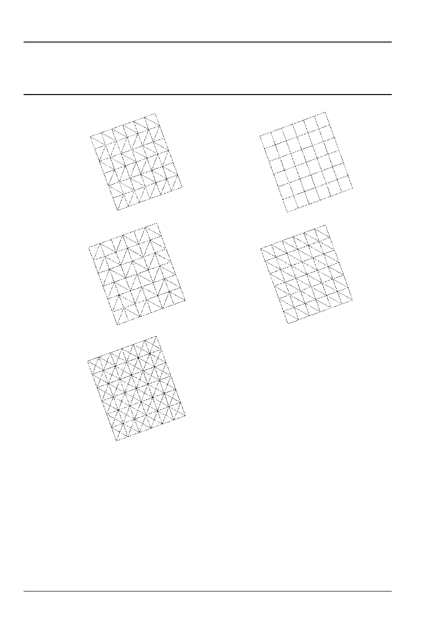
The test gathers eight modelings: with regard to the four first, the results obtained are
compared for triangular surface meshs then quadrangular, in two reference marks user
different. Four last modelings make it possible to measure the sensitivity of the results the orientation
triangular meshs in the two reference marks user.
Code_Aster
®
Version
6.0
Titrate:
SSLS115 - Composite square plate under uniform pressure
Date:
23/10/02
Author (S):
J.M. PROIX, NR. RAHNI
Key
:
V3.03.115-A
Page:
2/24
Manual of Validation
V3.03 booklet: Linear statics of the hulls and the plates
HT-66/02/001/A
1
Problem of reference
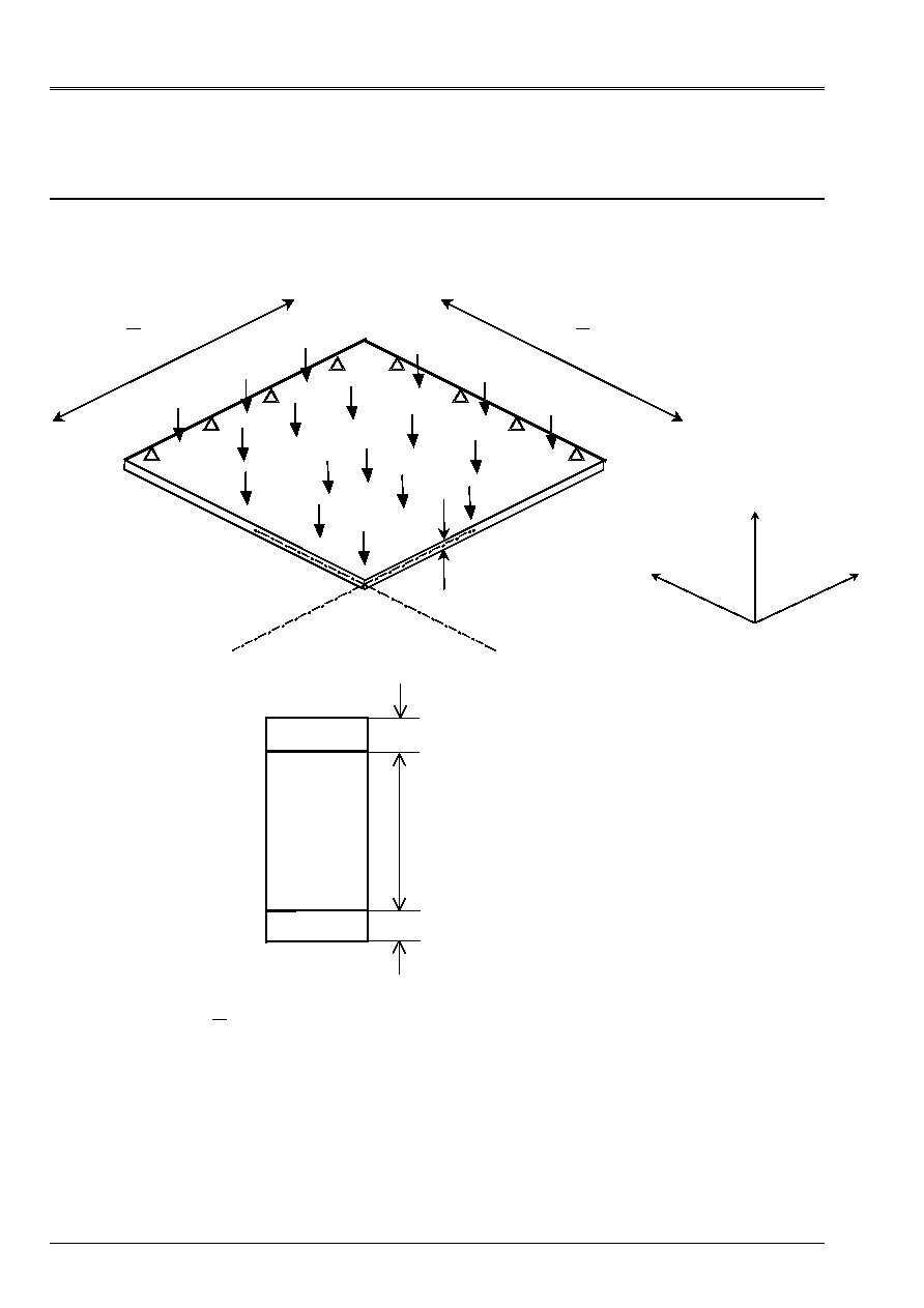
1.1 Geometry
Because of the geometrical and physical symmetry of the problem, only the quarter of the plate is
modelized.
X
y
Z
100 mm
=
H
500 mm
2
=
L
2
L
C
D
With
B
80 mm
10 mm
10 mm
Material 2
Material 1
Material 1
Twinge:
H
L
= 10: the plate is relatively thick.
1.2
Material properties
Material 1
Material 2
E_L (10
11
NR/m ²)
3.4156
0.34156
E_T (10
11
NR/m ²)
1.793
0.1793
G_LN (10
11
NR/m ²)
0.608
0.0608
G_TN (10
11
NR/m ²)
1.015
0.1015
G_LT (10
11
NR/m ²)
1.0
0.1
NU_T
0.44
0.44

Code_Aster
®
Version
6.0
Titrate:
SSLS115 - Composite square plate under uniform pressure
Date:
23/10/02
Author (S):
J.M. PROIX, NR. RAHNI
Key
:
V3.03.115-A
Page:
3/24
Manual of Validation
V3.03 booklet: Linear statics of the hulls and the plates
HT-66/02/001/A
1.3
Boundary conditions and loadings
Simple support plate
C.L. :
AB:
DZ = 0.
DRY=0.
AD:
DZ = 0.
DRX=0.
Symmetry
BC:
DX = 0.
DRY=0.
DRZ=0.
CD:
DY = 0.
DRX=0. DRZ=0.
Loading:
FORCE_COQUE
Uniform pressure
P = 1N/m ²
2
Reference solution
2.1
Reference solution
The numerical solution obtained with a theory of plate multi-layer in linear elasticity
orthotropic is given in the reference [bib1] page 341.
2.2
Results of reference
At the point C, one calculates displacement according to Z of the point as well as the stresses
X
with the interfaces
lower and higher of the skins.
2.3
Uncertainty on the solution
Numerical solution.
2.4 References
bibliographical
[1]
BATOZ and DHATT. Modeling of the structures by finite elements. Beams and plates.
Hermès, 1990.
Code_Aster
®
Version
6.0
Titrate:
SSLS115 - Composite square plate under uniform pressure
Date:
23/10/02
Author (S):
J.M. PROIX, NR. RAHNI
Key
:
V3.03.115-A
Page:
4/24
Manual of Validation
V3.03 booklet: Linear statics of the hulls and the plates
HT-66/02/001/A
3 Modeling
With
3.1
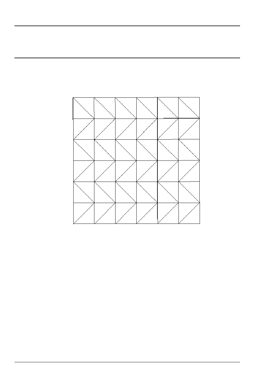
Characteristics of modeling
Element of hull DST (modeling of a quarter of plate).
The reference mark user is confused with the reference mark of orthotropism.
D
With
B
Limiting conditions:
DDL_IMPO
(GROUP_NO=' AB', DZ=0., DRY=0.)
(GROUP_NO=' BC', DX=0., DRY=0.)
(GROUP_NO=' CD', DY=0., DRX=0.)
(GROUP_NO=' DA', DZ=0., DRX=0.)
Not C
net: 72
3.2
Characteristics of the mesh
A number of nodes: 56
A number of meshs and types: 72 TRIA3
C

Code_Aster
®
Version
6.0
Titrate:
SSLS115 - Composite square plate under uniform pressure
Date:
23/10/02
Author (S):
J.M. PROIX, NR. RAHNI
Key
:
V3.03.115-A
Page:
5/24
Manual of Validation
V3.03 booklet: Linear statics of the hulls and the plates
HT-66/02/001/A
3.3 Functionalities
tested
Controls
AFFE_MODELE
“MECHANICAL”
“DST”
MODI_MAILLAGE
ORIE_NORME_COQUE
AFFE_CARA_ELEM
HULL
THICK
ANGLE_REP
DEFI_MATERIAU
ELAS_ORTH
DEFI_COQU_MULT
SLEEP
THICK
ORIENTATION
AFFE_CHAR_MECA
FORCE_COQUE
NEAR
ALL
DDL_IMPO
GROUP_NO
MECA_STATIQUE
CALC_CHAM_ELEM
SIGM_ELNO_DEPL
4
Results of modeling A
4.1 Values
tested
Not C
Identification
Reference
Aster %
Difference
X
on lower layer 3
4.7100E+01 4.7662E+01
1.194
X
on higher layer 3
5.8800E+01 5.9577E+01
1.323
Stresses
X
on lower layer 2
4.7100E+01 4.7662E+01
1.194
X
on higher layer 2
4.7100E+01 4.7662E+01
1.194
X
on lower layer 1
5.8800E+01 5.9577E+01
1.323
X
on higher layer 1
4.7100E+01 4.7662E+01
1.194
DX
0.0.0.0.0.0
Displacement DY
0.0.0.0.0.0
DZ
4.1920E+01 4.1851E+01
0.163
4.2
Contents of the file results
Values at the point of observation of displacements and stresses
X
.
4.3 Parameters
of execution
Version: 6.0.29
Machine: SGI - ORIGIN 2000
Overall dimension memory:
32 Mo
Time CPU To use: 5.74 seconds
Code_Aster
®
Version
6.0
Titrate:
SSLS115 - Composite square plate under uniform pressure
Date:
23/10/02
Author (S):
J.M. PROIX, NR. RAHNI
Key
:
V3.03.115-A
Page:
6/24
Manual of Validation
V3.03 booklet: Linear statics of the hulls and the plates
HT-66/02/001/A
5 Modeling
B
5.1
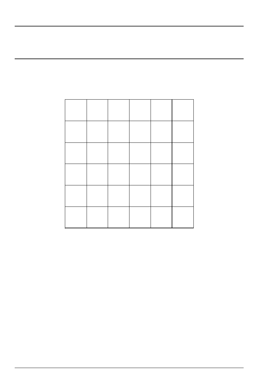
Characteristics of modeling
Element of hull DST (modeling of a quarter of plate).
The reference mark user is confused with the reference mark of orthotropism.
D
With
B
Limiting conditions:
DDL_IMPO
(GROUP_NO=' AB', DZ=0., DRY=0.)
(GROUP_NO=' BC', DX=0., DRY=0.)
(GROUP_NO=' CD', DY=0., DRX=0.)
(GROUP_NO=' DA', DZ=0., DRX=0.)
Not C
net: 36
5.2
Characteristics of the mesh
A number of nodes: 57
A number of meshs and types: 36 QUAD4
C

Code_Aster
®
Version
6.0
Titrate:
SSLS115 - Composite square plate under uniform pressure
Date:
23/10/02
Author (S):
J.M. PROIX, NR. RAHNI
Key
:
V3.03.115-A
Page:
7/24
Manual of Validation
V3.03 booklet: Linear statics of the hulls and the plates
HT-66/02/001/A
5.3 Functionalities
tested
Controls
AFFE_MODELE
“MECHANICAL”
“DST”
MODI_MAILLAGE
ORIE_NORME_COQUE
AFFE_CARA_ELEM
HULL
THICK
ANGLE_REP
DEFI_MATERIAU
ELAS_ORTH
DEFI_COQU_MULT
SLEEP
THICK
ORIENTATION
AFFE_CHAR_MECA
FORCE_COQUE
NEAR
ALL
DDL_IMPO
GROUP_NO
MECA_STATIQUE
CALC_CHAM_ELEM
SIGM_ELNO_DEPL
6
Results of modeling B
6.1 Values
tested
Not C
Identification
Reference
Aster %
Difference
X
on lower layer 3
4.7100E+01 5.0881E+01
8.028
X
on higher layer 3
5.8800E+01 6.3601E+01
8.166
Stresses
X
on lower layer 2
4.7100E+01 5.0881E+01
8.028
X
on higher layer 2
4.7100E+01 5.0881E+01
8.028
X
on lower layer 1
5.8800E+01 6.3601E+01
8.166
X
on higher layer 1
4.7100E+01 5.0881E+01
8.028
DX
0.0.0.0.0.0
Displacement DY
0.0.0.0.0.0
DZ
4.1920E+01 4.2040E+01
0.29
6.2
Contents of the file results
Values at the point of observation of displacements and stresses
X
.
6.3 Parameters
of execution
Version: 6.0.29
Machine: SGI - ORIGIN 2000
Overall dimension memory:
32 Mo
Time CPU To use: 4.25 seconds
Code_Aster
®
Version
6.0
Titrate:
SSLS115 - Composite square plate under uniform pressure
Date:
23/10/02
Author (S):
J.M. PROIX, NR. RAHNI
Key
:
V3.03.115-A
Page:
8/24
Manual of Validation
V3.03 booklet: Linear statics of the hulls and the plates
HT-66/02/001/A
7 Modeling
C
7.1
Characteristics of modeling
Element of hull DST (modeling of a quarter of plate).
The model of plate associated with modeling A is turned of 20 degrees according to the nautical angle
alpha and of 30 degrees according to beta.
With
B
C
D
Limiting conditions:
LIAISON_OBLIQUE
(GROUP_NO=' AB', ANGL_NAUT= (20., 30., 0.), DZ=0., DRY=0.)
(GROUP_NO=' BC', ANGL_NAUT= (20., 30., 0.), DX=0., DRY=0.)
(GROUP_NO=' CD', ANGL_NAUT= (20., 30., 0.), DY=0., DRX=0.)
(GROUP_NO=' DA', ANGL_NAUT= (20., 30., 0.), DZ=0., DRX=0.)
Not C
net: 72
7.2
Characteristics of the mesh
A number of nodes: 56
A number of meshs and types: 72 TRIA3

Code_Aster
®
Version
6.0
Titrate:
SSLS115 - Composite square plate under uniform pressure
Date:
23/10/02
Author (S):
J.M. PROIX, NR. RAHNI
Key
:
V3.03.115-A
Page:
9/24
Manual of Validation
V3.03 booklet: Linear statics of the hulls and the plates
HT-66/02/001/A
7.3 Functionalities
tested
Controls
AFFE_MODELE
“MECHANICAL”
“DST”
MODI_MAILLAGE
ORIE_NORME_COQUE
AFFE_CARA_ELEM
HULL
THICK
ANGLE_REP
DEFI_MATERIAU
ELAS_ORTH
DEFI_COQU_MULT
SLEEP
THICK
ORIENTATION
AFFE_CHAR_MECA
FORCE_COQUE
NEAR
ALL
LIAISON_OBLIQUE
ANGLE_NAUT
GROUP_NO
MECA_STATIQUE
CALC_CHAM_ELEM
SIGM_ELNO_DEPL
8
Results of modeling C
8.1 Values
tested
Not C
Identification
Reference
Aster %
Difference
X
on lower layer 3
4.7100E+01 4.7662E+01
1.194
X
on higher layer 3
5.8800E+01 5.9577E+01
1.323
Stresses
X
on lower layer 2
4.7100E+01 4.7662E+01
1.194
X
on higher layer 2
4.7100E+01 4.7662E+01
1.194
X
on lower layer 1
5.8800E+01 5.9577E+01
1.323
X
on higher layer 1
4.7100E+01 4.7662E+01
1.194
DX
1.9696E+01 1.9663E+01
0.163
Displacement DY
7.1687E+00 7.1570E+00
0.162
DZ
3.6304E+01 3.6244E+01
0.163
8.2 Remarks
The values of reference of displacement to the point C are obtained by projecting displacement
theoretical bench for a plate not turned in the new reference mark user (displacement for
a not turned plate being vertical, new displacement is a function of the projection of the axis
Z). In the local reference mark, the projection of axis Z is as follows:
cos
sin
sin
cos
sin
, with
.
20
=
and
.
30
=

Code_Aster
®
Version
6.0
Titrate:
SSLS115 - Composite square plate under uniform pressure
Date:
23/10/02
Author (S):
J.M. PROIX, NR. RAHNI
Key
:
V3.03.115-A
Page:
10/24
Manual of Validation
V3.03 booklet: Linear statics of the hulls and the plates
HT-66/02/001/A
8.3
Contents of the file results
Values at the point of observation of displacements and stresses
X
.
8.4 Parameters
of execution
Version: 6.0.29
Machine: SGI - ORIGIN 2000
Overall dimension memory:
32 Mo
Time CPU To use: 4.52 seconds
Code_Aster
®
Version
6.0
Titrate:
SSLS115 - Composite square plate under uniform pressure
Date:
23/10/02
Author (S):
J.M. PROIX, NR. RAHNI
Key
:
V3.03.115-A
Page:
11/24
Manual of Validation
V3.03 booklet: Linear statics of the hulls and the plates
HT-66/02/001/A
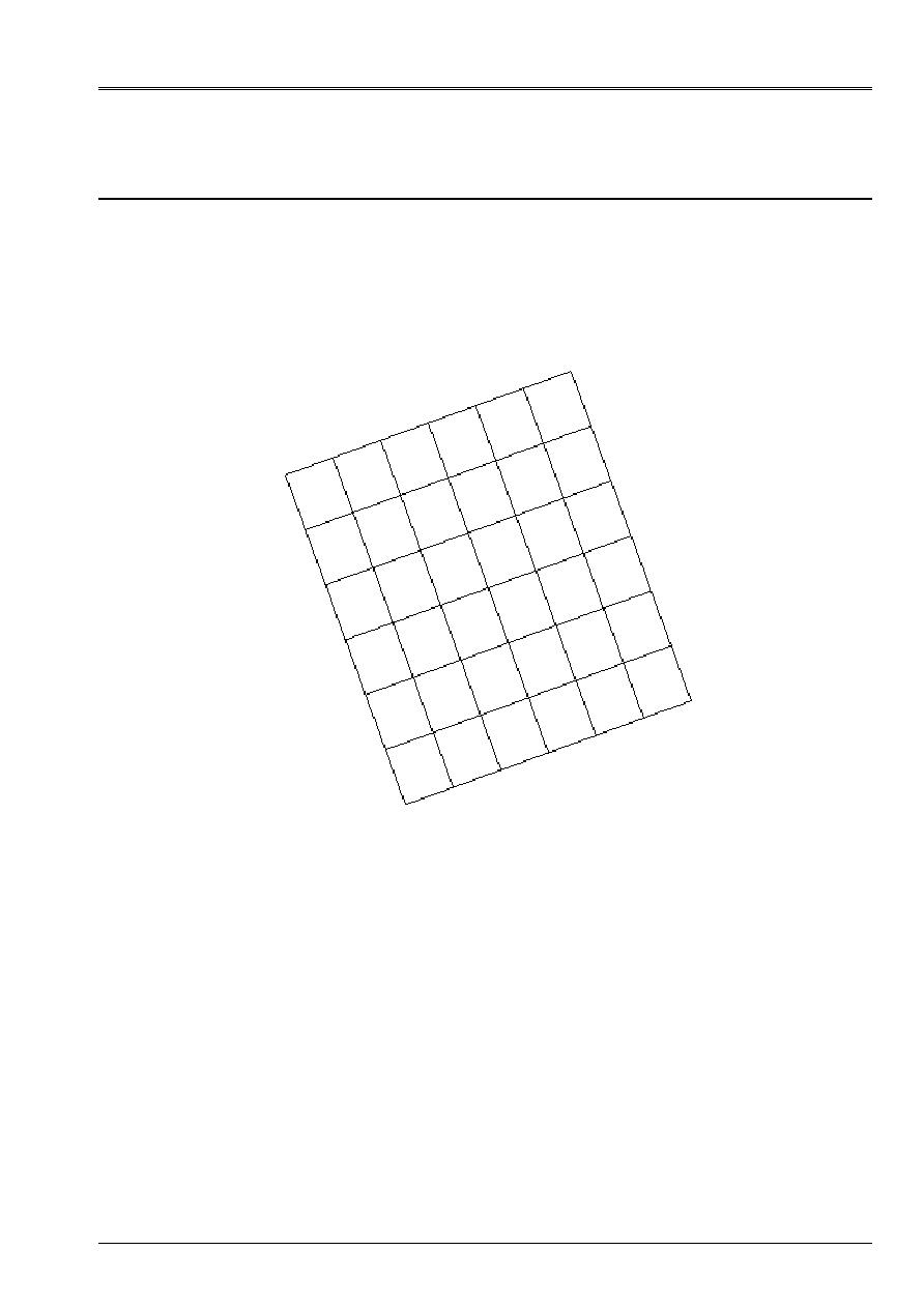
9 Modeling
D
9.1
Characteristics of modeling
Element of hull DST (modeling of a quarter of plate).
The model of plate associated with modeling B is turned of 20 degrees according to the nautical angle
alpha and of 30 degrees according to beta.
With
B
C
D
Limiting conditions:
LIAISON_OBLIQUE
(GROUP_NO=' AB', ANGL_NAUT= (20., 30., 0.), DZ=0., DRY=0.)
(GROUP_NO=' BC', ANGL_NAUT= (20., 30., 0.), DX=0., DRY=0.)
(GROUP_NO=' CD', ANGL_NAUT= (20., 30., 0.), DY=0., DRX=0.)
(GROUP_NO=' DA', ANGL_NAUT= (20., 30., 0.), DZ=0., DRX=0.)
Not C
net: 36
9.2
Characteristics of the mesh
A number of nodes: 57
A number of meshs and types: 36 QUAD4

Code_Aster
®
Version
6.0
Titrate:
SSLS115 - Composite square plate under uniform pressure
Date:
23/10/02
Author (S):
J.M. PROIX, NR. RAHNI
Key
:
V3.03.115-A
Page:
12/24
Manual of Validation
V3.03 booklet: Linear statics of the hulls and the plates
HT-66/02/001/A
9.3 Functionalities
tested
Controls
AFFE_MODELE
“MECHANICAL”
“DST”
MODI_MAILLAGE
ORIE_NORME_COQUE
AFFE_CARA_ELEM
HULL
THICK
ANGLE_REP
DEFI_MATERIAU
ELAS_ORTH
DEFI_COQU_MULT
SLEEP
THICK
ORIENTATION
AFFE_CHAR_MECA
FORCE_COQUE
NEAR
ALL
LIAISON_OBLIQUE
ANGLE_NAUT
GROUP_NO
MECA_STATIQUE
CALC_CHAM_ELEM
SIGM_ELNO_DEPL
10 Results of modeling D
10.1 Values
tested
Not C
Identification
Reference
Aster %
Difference
X
on lower layer 3
4.7100E+01 5.0881E+01
8.028
X
on higher layer 3
5.8800E+01 6.3601E+01
8.166
Stresses
X
on lower layer 2
4.7100E+01 5.0881E+01
8.028
X
on higher layer 2
4.7100E+01 5.0881E+01
8.028
X
on lower layer 1
5.8800E+01 6.3601E+01
8.166
X
on higher layer 1
4.7100E+01 5.0881E+01
8.028
DX
1.9696E+01 1.9750E+01
0.290
Displacement DY
7.1687E+00 7.1895E+00
0.291
DZ
3.6304E+01 3.6409E+01
0.289
10.2 Remarks
The values of reference of displacement to the point C are obtained by projecting displacement
theoretical bench for a plate not turned in the new reference mark user (displacement for
a not turned plate being vertical, new displacement is a function of the projection of the axis
Z). In the local reference mark, the projection of axis Z is as follows:
cos
sin
sin
cos
sin
, with
.
20
=
and
.
30
=
Code_Aster
®
Version
6.0
Titrate:
SSLS115 - Composite square plate under uniform pressure
Date:
23/10/02
Author (S):
J.M. PROIX, NR. RAHNI
Key
:
V3.03.115-A
Page:
13/24
Manual of Validation
V3.03 booklet: Linear statics of the hulls and the plates
HT-66/02/001/A
10.3 Contents of the file results
Values at the point of observation of displacements and stresses
X
.
10.4 Parameters
of execution
Version: 6.0.29
Machine: SGI - ORIGIN 2000
Overall dimension memory:
32 Mo
Time CPU To use: 6.11 seconds
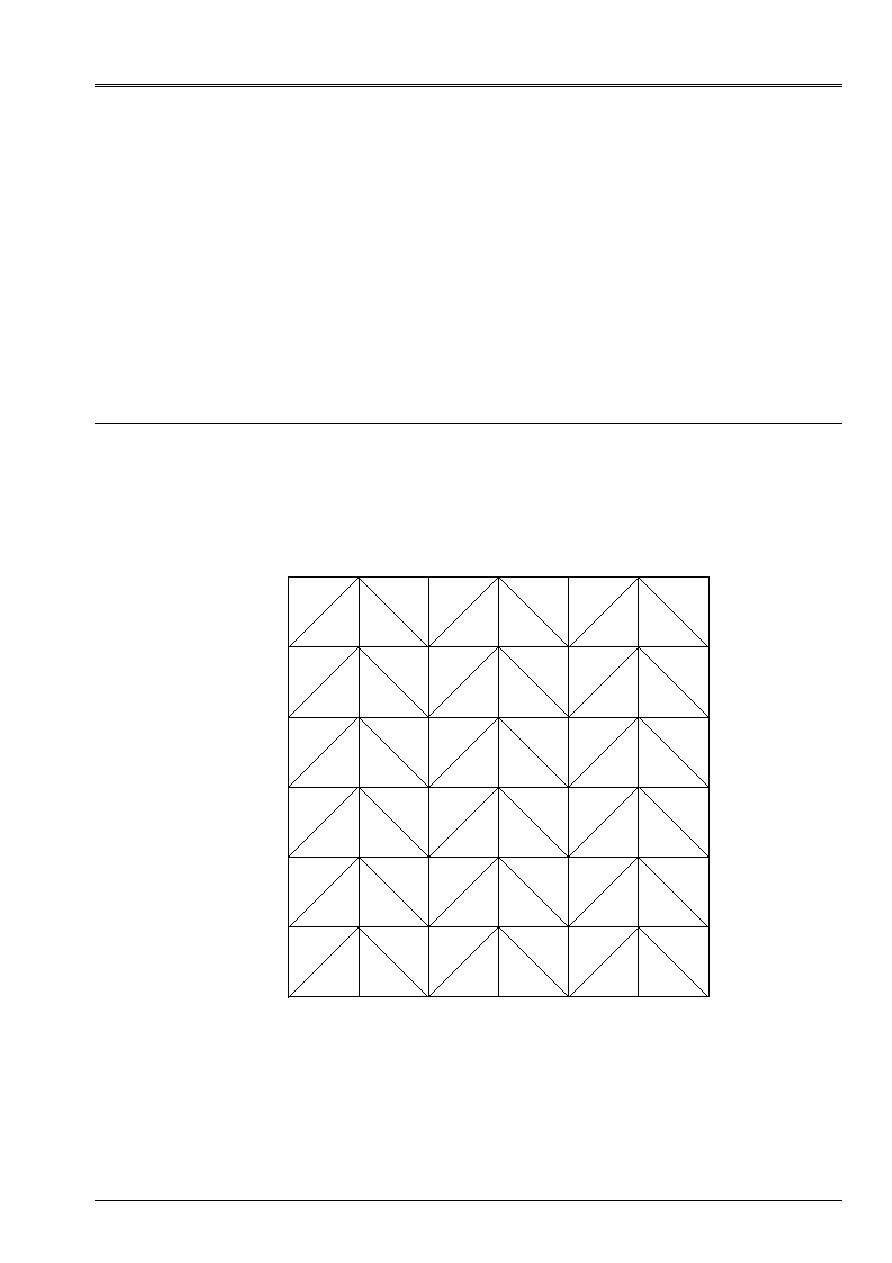
11 Modeling
E
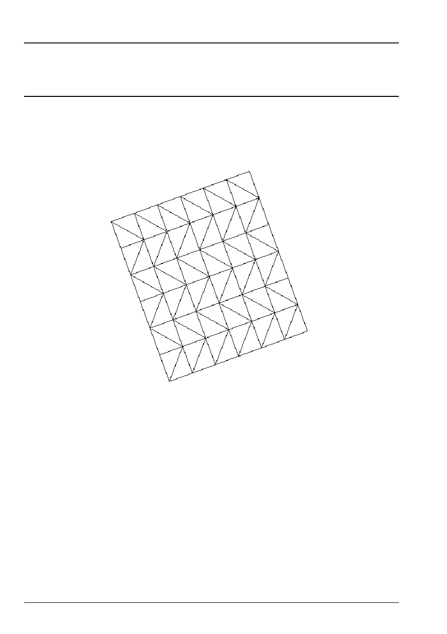
11.1 Characteristics of modeling
Element of hull DST (modeling of a quarter of plate).
The reference mark user is confused with the reference mark of orthotropism. Compared to modeling A,
the model is characterized here by an orientation different from the surface meshs.
D
With
B
Limiting conditions:
DDL_IMPO
(GROUP_NO=' AB', DZ=0., DRY=0.)
(GROUP_NO=' BC', DX=0., DRY=0.)
(GROUP_NO=' CD', DY=0., DRX=0.)
(GROUP_NO=' DA', DZ=0., DRX=0.)
Not C
net: 72
C

Code_Aster
®
Version
6.0
Titrate:
SSLS115 - Composite square plate under uniform pressure
Date:
23/10/02
Author (S):
J.M. PROIX, NR. RAHNI
Key
:
V3.03.115-A
Page:
14/24
Manual of Validation
V3.03 booklet: Linear statics of the hulls and the plates
HT-66/02/001/A
11.2 Characteristics of the mesh
A number of nodes: 56
A number of meshs and types: 72 TRIA3
11.3 Functionalities
tested
Controls
AFFE_MODELE
“MECHANICAL”
“DST”
MODI_MAILLAGE
ORIE_NORME_COQUE
AFFE_CARA_ELEM
HULL
THICK
ANGLE_REP
DEFI_MATERIAU
ELAS_ORTH
DEFI_COQU_MULT
SLEEP
THICK
ORIENTATION
AFFE_CHAR_MECA
FORCE_COQUE
NEAR
ALL
DDL_IMPO
GROUP_NO
MECA_STATIQUE
CALC_CHAM_ELEM
SIGM_ELNO_DEPL
12 Results of modeling E
12.1 Values
tested
Not C
Identification
Reference
Aster %
Difference
X
on lower layer 3
4.7100E+01 5.2430E+01
11.317
X
on higher layer 3
5.8800E+01 6.5537E+01
11.459
Stresses
X
on lower layer 2
4.7100E+01 5.2430E+01
11.317
X
on higher layer 2
4.7100E+01 5.2430E+01
11.317
X
on lower layer 1
5.8800E+01 6.5537E+01
11.459
X
on higher layer 1
4.7100E+01 5.2430E+01
11.317
DX
0.0.0.0.0.0
Displacement DY
0.0.0.0.0.0
DZ
4.1920E+01 4.2024E+01
0.248
12.2 Contents of the file results
Values at the point of observation of displacements and stresses
X
.
12.3 Parameters
of execution
Version: 6.0.29
Machine: SGI - ORIGIN 2000
Overall dimension memory:
32 Mo
Time CPU To use: 4.14 seconds
Code_Aster
®
Version
6.0
Titrate:
SSLS115 - Composite square plate under uniform pressure
Date:
23/10/02
Author (S):
J.M. PROIX, NR. RAHNI
Key
:
V3.03.115-A
Page:
15/24
Manual of Validation
V3.03 booklet: Linear statics of the hulls and the plates
HT-66/02/001/A
13 Modeling
F
13.1 Characteristics of modeling
Element of hull DST (modeling of a quarter of plate).
The model of plate associated with modeling E is turned of 20 degrees according to the nautical angle
alpha and of 30 degrees according to beta. Compared to modeling C, the model is here
characterized by an orientation different from the meshs.
With
B
C
D
Limiting conditions:
LIAISON_OBLIQUE
(GROUP_NO=' AB', ANGL_NAUT= (20., 30., 0.), DZ=0., DRY=0.)
(GROUP_NO=' BC', ANGL_NAUT= (20., 30., 0.), DX=0., DRY=0.)
(GROUP_NO=' CD', ANGL_NAUT= (20., 30., 0.), DY=0., DRX=0.)
(GROUP_NO=' DA', ANGL_NAUT= (20., 30., 0.), DZ=0., DRX=0.)
Not C
net: 72
13.2 Characteristics of the mesh
A number of nodes: 56
A number of meshs and types: 72 TRIA3

Code_Aster
®
Version
6.0
Titrate:
SSLS115 - Composite square plate under uniform pressure
Date:
23/10/02
Author (S):
J.M. PROIX, NR. RAHNI
Key
:
V3.03.115-A
Page:
16/24
Manual of Validation
V3.03 booklet: Linear statics of the hulls and the plates
HT-66/02/001/A
13.3 Functionalities
tested
Controls
AFFE_MODELE
“MECHANICAL”
“DST”
MODI_MAILLAGE
ORIE_NORME_COQUE
AFFE_CARA_ELEM
HULL
THICK
ANGLE_REP
DEFI_MATERIAU
ELAS_ORTH
DEFI_COQU_MULT
SLEEP
THICK
ORIENTATION
AFFE_CHAR_MECA
FORCE_COQUE
NEAR
ALL
LIAISON_OBLIQUE
ANGLE_NAUT
GROUP_NO
MECA_STATIQUE
CALC_CHAM_ELEM
SIGM_ELNO_DEPL
14 Results of modeling F
14.1 Values
tested
Not C
Identification
Reference
Aster %
Difference
X
on lower layer 3
4.7100E+01 5.2430E+01
11.317
X
on higher layer 3
5.8800E+01 6.5537E+01
11.459
Stresses
X
on lower layer 2
4.7100E+01 5.2430E+01
11.317
X
on higher layer 2
4.7100E+01 5.2430E+01
11.317
X
on lower layer 1
5.8800E+01 6.5537E+01
11.459
X
on higher layer 1
4.7100E+01 5.2430E+01
11.317
DX
1.9696E+01 1.9744E+01
0.248
Displacement DY
7.1687E+00 7.1865E+00
0.249
DZ
3.6304E+01 3.6393E+01
0.248
14.2 Remarks
The values of reference of displacement to the point C are obtained by projecting displacement
theoretical bench for a plate not turned in the new reference mark user (displacement for
a not turned plate being vertical, new displacement is a function of the projection of the axis
Z). In the local reference mark, the projection of axis Z is as follows:
cos
sin
sin
cos
sin
, with
.
20
=
and
.
30
=

Code_Aster
®
Version
6.0
Titrate:
SSLS115 - Composite square plate under uniform pressure
Date:
23/10/02
Author (S):
J.M. PROIX, NR. RAHNI
Key
:
V3.03.115-A
Page:
17/24
Manual of Validation
V3.03 booklet: Linear statics of the hulls and the plates
HT-66/02/001/A
14.3 Contents of the file results
Values at the point of observation of displacements and stresses
X
.
14.4 Parameters
of execution
Version: 6.0.29
Machine: SGI - ORIGIN 2000
Overall dimension memory:
32 Mo
Time CPU To use: 4.22 seconds
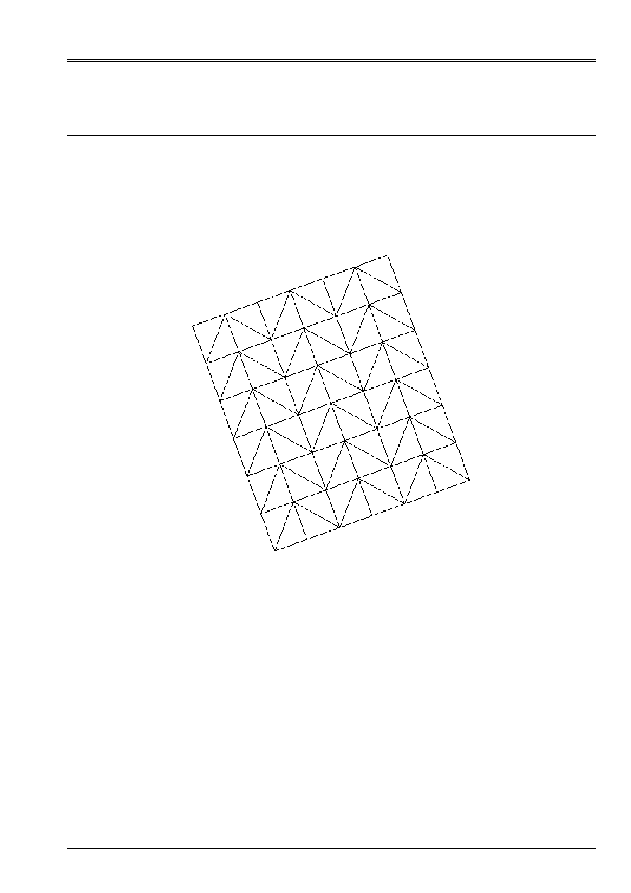
15 Modeling
G
15.1 Characteristics of modeling
Element of hull DST (modeling of a quarter of plate).
The model of plate is turned of 20 degrees according to the nautical angle alpha and of 30 degrees according to
beta, without reference to a model not turned.
The orientation of the meshs is here identical to that of the reference [bib1].
C
B
D
With
Limiting conditions:
LIAISON_OBLIQUE
(GROUP_NO=' AB', ANGL_NAUT= (20., 30., 0.), DZ=0., DRY=0.)
(GROUP_NO=' BC', ANGL_NAUT= (20., 30., 0.), DX=0., DRY=0.)
(GROUP_NO=' CD', ANGL_NAUT= (20., 30., 0.), DY=0., DRX=0.)
(GROUP_NO=' DA', ANGL_NAUT= (20., 30., 0.), DZ=0., DRX=0.)
Not C
net: 72

Code_Aster
®
Version
6.0
Titrate:
SSLS115 - Composite square plate under uniform pressure
Date:
23/10/02
Author (S):
J.M. PROIX, NR. RAHNI
Key
:
V3.03.115-A
Page:
18/24
Manual of Validation
V3.03 booklet: Linear statics of the hulls and the plates
HT-66/02/001/A
15.2 Characteristics of the mesh
A number of nodes: 56
A number of meshs and types: 72 TRIA3
15.3 Functionalities
tested
Controls
AFFE_MODELE
“MECHANICAL”
“DST”
MODI_MAILLAGE
ORIE_NORME_COQUE
AFFE_CARA_ELEM
HULL
THICK
ANGLE_REP
DEFI_MATERIAU
ELAS_ORTH
DEFI_COQU_MULT
SLEEP
THICK
ORIENTATION
AFFE_CHAR_MECA
FORCE_COQUE
NEAR
ALL
LIAISON_OBLIQUE
ANGLE_NAUT
GROUP_NO
MECA_STATIQUE
CALC_CHAM_ELEM
SIGM_ELNO_DEPL
16 Results of modeling G
16.1 Values
tested
Not C
Identification
Reference
Aster %
Difference
X
on lower layer 3
4.7100E+01 4.7920E+01
1.742
X
on higher layer 3
5.8800E+01 5.9900E+01
1.872
Stresses
X
on lower layer 2
4.7100E+01 4.7920E+01
1.742
X
on higher layer 2
4.7100E+01 4.7920E+01
1.742
X
on lower layer 1
5.8800E+01 5.9900E+01
1.872
X
on higher layer 1
4.7100E+01 4.7920E+01
1.742
DX
1.9696E+01 1.9882E+01
0.946
Displacement DY
7.1687E+00 7.2365E+00
0.947
DZ
3.6304E+01 3.6647E+01
0.946
16.2 Remarks
The values of reference of displacement to the point C are obtained by projecting displacement
theoretical bench for a plate not turned in the new reference mark user (displacement for
a not turned plate being vertical, new displacement is a function of the projection of the axis
Z). In the local reference mark, the projection of axis Z is as follows:
cos
sin
sin
cos
sin
, with
.
20
=
and
.
30
=
Code_Aster
®
Version
6.0
Titrate:
SSLS115 - Composite square plate under uniform pressure
Date:
23/10/02
Author (S):
J.M. PROIX, NR. RAHNI
Key
:
V3.03.115-A
Page:
19/24
Manual of Validation
V3.03 booklet: Linear statics of the hulls and the plates
HT-66/02/001/A
16.3 Contents of the file results
Values at the point of observation of displacements and stresses
X
.
16.4 Parameters
of execution
Version: 6.0.29
Machine: SGI - ORIGIN 2000
Overall dimension memory:
32 Mo
Time CPU To use: 4.22 seconds
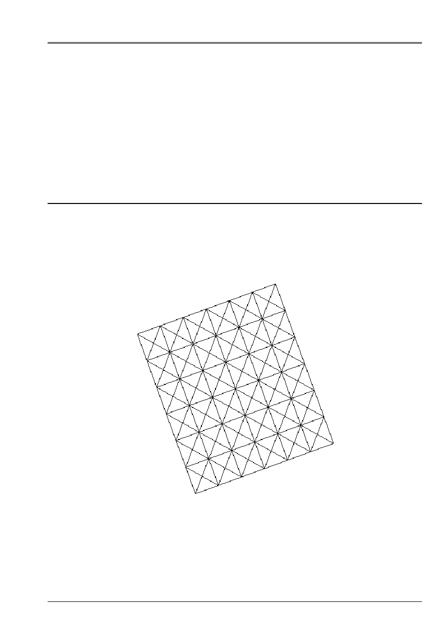
17 Modeling
H
17.1 Characteristics of modeling
Element of hull DST (modeling of a quarter of plate).
The model of plate is turned of 20 degrees according to the nautical angle alpha and of 30 degrees according to
beta, without reference to a model not turned.
C
D
B
With
Limiting conditions:
LIAISON_OBLIQUE
(GROUP_NO=' AB', ANGL_NAUT= (20., 30., 0.), DZ=0., DRY=0.)
(GROUP_NO=' BC', ANGL_NAUT= (20., 30., 0.), DX=0., DRY=0.)
(GROUP_NO=' CD', ANGL_NAUT= (20., 30., 0.), DY=0., DRX=0.)
(GROUP_NO=' DA', ANGL_NAUT= (20., 30., 0.), DZ=0., DRX=0.)
Not C
net: 142

Code_Aster
®
Version
6.0
Titrate:
SSLS115 - Composite square plate under uniform pressure
Date:
23/10/02
Author (S):
J.M. PROIX, NR. RAHNI
Key
:
V3.03.115-A
Page:
20/24
Manual of Validation
V3.03 booklet: Linear statics of the hulls and the plates
HT-66/02/001/A
17.2 Characteristics of the mesh
A number of nodes: 101
A number of meshs and types: 144 TRIA3
17.3 Functionalities
tested
Controls
AFFE_MODELE
“MECHANICAL”
“DST”
MODI_MAILLAGE
ORIE_NORME_COQUE
AFFE_CARA_ELEM
HULL
THICK
ANGLE_REP
DEFI_MATERIAU
ELAS_ORTH
DEFI_COQU_MULT
SLEEP
THICK
ORIENTATION
AFFE_CHAR_MECA
FORCE_COQUE
NEAR
ALL
LIAISON_OBLIQUE
ANGLE_NAUT
GROUP_NO
MECA_STATIQUE
CALC_CHAM_ELEM
SIGM_ELNO_DEPL
18 Results of modeling H
18.1 Values
tested
Not C
Identification
Reference
Aster %
Difference
X
on lower layer 3
4.7100E+01 5.0957E+01
8.19
X
on higher layer 3
5.8800E+01 6.3691E+01
8.32
Stresses
X
on lower layer 2
4.7100E+01 5.0957E+01
8.19
X
on higher layer 2
4.7100E+01 5.0957+01
8.19
X
on lower layer 1
5.8800E+01 6.3696E+01
8.32
X
on higher layer 1
4.7100E+01 5.0957E+01
8.19
DX
1.9696E+01 1.9735E+01
0.199
Displacement DY
7.1687E+00 7.1830E+00
0.200
DZ
3.6304E+01 3.6376E+01
0.200
18.2 Remarks
The values of reference of displacement to the point C are obtained by projecting displacement
theoretical bench for a plate not turned in the new reference mark user (displacement for
a not turned plate being vertical, new displacement is a function of the projection of the axis
Z). In the local reference mark, the projection of axis Z is as follows:
cos
sin
sin
cos
sin
, with
.
20
=
and
.
30
=

Code_Aster
®
Version
6.0
Titrate:
SSLS115 - Composite square plate under uniform pressure
Date:
23/10/02
Author (S):
J.M. PROIX, NR. RAHNI
Key
:
V3.03.115-A
Page:
21/24
Manual of Validation
V3.03 booklet: Linear statics of the hulls and the plates
HT-66/02/001/A
18.3 Contents of the file results
Values at the point of observation of displacements and stresses
X
.
18.4 Parameters
of execution
Version: 6.0.29
Machine: SGI - ORIGIN 2000
Overall dimension memory:
32 Mo
Time CPU To use: 4.22 seconds
Code_Aster
®
Version
6.0
Titrate:
SSLS115 - Composite square plate under uniform pressure
Date:
23/10/02
Author (S):
J.M. PROIX, NR. RAHNI
Key
:
V3.03.115-A
Page:
22/24
Manual of Validation
V3.03 booklet: Linear statics of the hulls and the plates
HT-66/02/001/A
19 Synthesis
graph
Modeling C
Modeling D
Modeling F
Modeling G
Modeling H
% Forced
% Displacement
C
1.2
0.17
D
8.1
0.23
F
11.4
0.25
G
1.8
0.95
H
8.2
0.20

Code_Aster
®
Version
6.0
Titrate:
SSLS115 - Composite square plate under uniform pressure
Date:
23/10/02
Author (S):
J.M. PROIX, NR. RAHNI
Key
:
V3.03.115-A
Page:
23/24
Manual of Validation
V3.03 booklet: Linear statics of the hulls and the plates
HT-66/02/001/A
20 Summary of the results
The results obtained show that:
·
With identical mesh (standard of surface meshs and orientation of the meshs), change
of reference mark user does not influence the stresses;
·
Because of orthotropism of the problem, there is a considerable sensitivity to the orientation
triangular surface meshs (the precision of calculations passes from 1 to 11% for
stresses and from 0.17 to 0.95% for displacements). This sensitivity does not disappear in
refining the mesh. This point is thus to take into account at the time of the comparison of
performances triangle/quadrangle.

Code_Aster
®
Version
6.0
Titrate:
SSLS115 - Composite square plate under uniform pressure
Date:
23/10/02
Author (S):
J.M. PROIX, NR. RAHNI
Key
:
V3.03.115-A
Page:
24/24
Manual of Validation
V3.03 booklet: Linear statics of the hulls and the plates
HT-66/02/001/A
Intentionally white left page.