
Code_Aster
®
Version
6.0
Titrate:
SSLS117 - Offsetting of nonsymmetrical plates
Date:
19/08/02
Author (S):
P. MASSIN, D. NUNEZ-GUAJARDO
Key
:
V3.03.117-A
Page:
1/12
Manual of Validation
V3.03 booklet: Linear statics of the plates and hulls
HT-66/02/001/A
Organization (S):
EDF/AMA, CS IF
Manual of Validation
V3.03 booklet: Linear statics of the plates and hulls
Document: V3.03.117
SSLS117 - Offsetting of plates
nonsymmetrical
Summary:
This test validates the offsetting of nonsymmetrical simple plates compared to the plan of the mesh or plan
of diagram (key word
OFFSETTING
control
AFFE_CARA_ELEM
).
The reference is given by a first resolution where one modelizes double-layered made up of two layers
various thicknesses and of two materials.
It is used to validate the second calculation where one modelizes two layers offset compared to the plan of the mesh.
It differs from test SSLS111 only by the fact that the 2 layers are different thicknesses.
Four modelings implement elements DKT, DKQ, DST, DSQ.
Code_Aster
®
Version
6.0
Titrate:
SSLS117 - Offsetting of nonsymmetrical plates
Date:
19/08/02
Author (S):
P. MASSIN, D. NUNEZ-GUAJARDO
Key
:
V3.03.117-A
Page:
2/12
Manual of Validation
V3.03 booklet: Linear statics of the plates and hulls
HT-66/02/001/A
1
Problem of reference
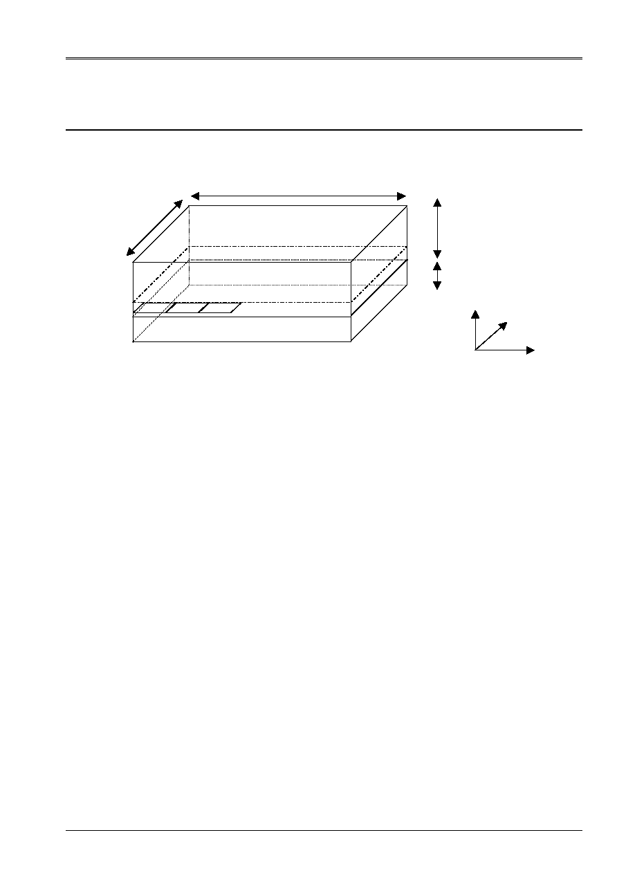
1.1 Geometry
1.2
Properties of materials
The material constituting the first layer is orthotropic and is characterized by the data
following:
EL=20000. 10
6
AP
ET=20000. 10
6
AP
LT = 0.3
GLT=2000. 10
6
AP
The material constituting the second layer is also orthotropic and has the following characteristics:
EL=15000. 10
6
AP
ET=15000. 10
6
AP
LT = 0.3
GLT=1500. 10
6
AP
1.3
Boundary conditions and loadings
The A1 node is embedded
DX=DY=DZ=0.
DRX=DRY=DRZ=0.
The A2 node is locked according to following ddls: DX=DY=0.
One applies nodal forces FZ=1000 NR to the A3 node, and one applies the loading distributed
(key word FORCE_COQUE) on the meshs m1, m2 and m3:
FX=200 NR
FX=500. NR/m
2
FZ=500.
NR/m
2
MX=100. NR/m
MY=40. NR/m
The selected loading utilizes stresses out of membrane and bending.
0.4 m
0.2 m
A2
A3
A1
A4
X
y
Z
m1 m2 m3
10 m
5 m

Code_Aster
®
Version
6.0
Titrate:
SSLS117 - Offsetting of nonsymmetrical plates
Date:
19/08/02
Author (S):
P. MASSIN, D. NUNEZ-GUAJARDO
Key
:
V3.03.117-A
Page:
3/12
Manual of Validation
V3.03 booklet: Linear statics of the plates and hulls
HT-66/02/001/A
2
Reference solution
2.1
Method of calculation used for the reference solution
Calculation with double-layered material (control
DEFI_COQU_MULT
) is used as reference. Not
regression compared to the results obtained by this first calculation is checked. Two plates of
the second modeling are offset compared to the average plan of the double-layered one.
2.2
Results of reference
They are consisted of the values of the field of displacement DX, DY, DZ, DRX, DRY at the A3 point and A4,
efforts at the A1 point and of the first 4 Eigen frequencies.
2.3
Uncertainty on the solution
Uncertainty is null since it is about the same calculation carried out by two different channels.
2.4 Bibliography
[1]
[R3.07.03]: Elements of plate DKT, DST, DKQ, DSQ and Q4
.
[2]
[R3.07.06]: Processing of offsetting for the elements of plate DKT, DST, DKQ, DSQ
and Q4G.
Code_Aster
®
Version
6.0
Titrate:
SSLS117 - Offsetting of nonsymmetrical plates
Date:
19/08/02
Author (S):
P. MASSIN, D. NUNEZ-GUAJARDO
Key
:
V3.03.117-A
Page:
4/12
Manual of Validation
V3.03 booklet: Linear statics of the plates and hulls
HT-66/02/001/A
3 Modeling
With
3.1
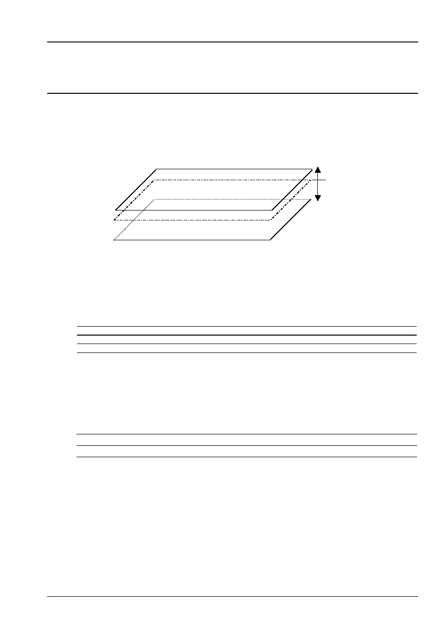
Characteristics of modeling
The model consists of two plates corresponding to the average plan of each of both
layers of the model of reference. To represent these two plates, one leaves the mesh of the plan
of diagram which one offsets distances 0.1 and 0.2.
The elements used are elements of plate DKT.
3.2
Characteristics of the mesh
Co-ordinates of the nodes:
Node Coor_X Coor_Y Coor_Z
A1 0. 0. 0.
A2 10.
0.
0.
A3 10.
5.
0.
A4 0. 5. 0.
94 Nodes
100 meshs DKT (TRIA3)
3.3 Functionalities
tested
Controls Key word
factor Key word
AFFE_CARA_ELEM
OFFSETTING
AFFE_CHAR_MECA
FORCE_COQUE
PLAN
DEFI_COQU_MULT
Plan average Plaq2
Plan average Plaq1
Plan of diagram
d=0.1 m
d= - 0.2 m

Code_Aster
®
Version
6.0
Titrate:
SSLS117 - Offsetting of nonsymmetrical plates
Date:
19/08/02
Author (S):
P. MASSIN, D. NUNEZ-GUAJARDO
Key
:
V3.03.117-A
Page:
5/12
Manual of Validation
V3.03 booklet: Linear statics of the plates and hulls
HT-66/02/001/A
4
Results of modeling A
4.1 Values
tested
Identification Reference
Aster %
difference
Displacement
DX (A4)
1.9426 10
6
1.93937
10
6
0.166
DY (A4)
1.1438 10
6
1.138746
10
6
0.442
DZ (A4)
2.1832 10
4
2.169149
10
4
0.644
DRX (A4)
6.0633
10
5
6.03126
10
5
0.528
DRY (A4) 1.2815
10
4
1.28078
10
4
0.056
DX (A3)
2.4225 10
6
2.419616
10
6
0.119
DY (A3)
2.3106 10
7
2.3104
10
7
0.04
DZ (A3)
1.5584 10
3
1.5563
10
3
0.133
DRX (A3)
1.2578 10
4
1.2543
10
4
0.276
DRY (A3) 1.3909
10
4
1.3903
10
4
0.038
Eigen frequencies
Frequency 1
Er
mode
1.5303
1.53038
0.006
Frequency 2
ème
mode
6.41979
6.41979
1.07 E-04
Frequency 3
ème
mode
1.269898 10
1
1.269898
10
1
2.81
E-05
Frequency 4
ème
mode
2.61597 10
1
2.61597
10
1
1.23
E-04
Efforts
NXX
N6
1.12134 E+04
1.11996 E+04
0.124
NYY
N6
7.52699 E+03
7.48953 E+03
0.498
NXY
N6
1.89850 E+03
1.89286 E+03
0.297
MXX
N6
2.33596 E+04
2.33480 E+04
0.050
MYY
N6
1.67905 E+04
1.66988 E+04
0.546
MXY
N6
5.43976 E+03
5.42402 E+03
0.289
QX
N6
4.60472 E+03
4.63427 E+03
0.642
QY
N6
1.58798 E+03
1.61207 E+03
1.517
Code_Aster
®
Version
6.0
Titrate:
SSLS117 - Offsetting of nonsymmetrical plates
Date:
19/08/02
Author (S):
P. MASSIN, D. NUNEZ-GUAJARDO
Key
:
V3.03.117-A
Page:
6/12
Manual of Validation
V3.03 booklet: Linear statics of the plates and hulls
HT-66/02/001/A
5 Modeling
B
5.1
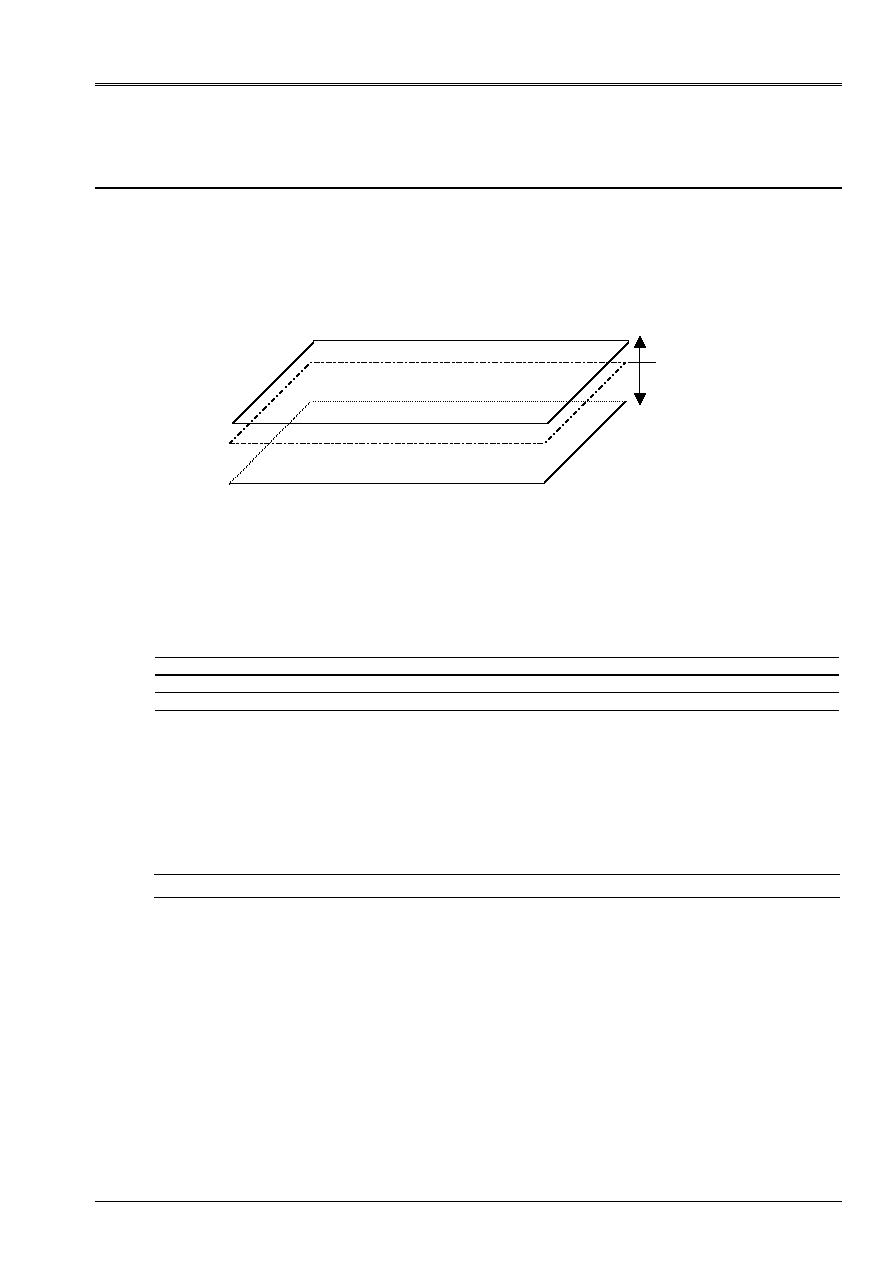
Characteristics of modeling
The model consists of two plates corresponding to the average plan of each of both
layers of the model of reference. To represent these two plates, one leaves the mesh of the plan
of diagram which one offsets distances 0.1 and 0.2
The elements used are elements of plate DKQ.
5.2
Characteristics of the mesh
Co-ordinates of the nodes:
Node Coor_X Coor_Y Coor_Z
A1 0. 0. 0.
A2 10.
0.
0.
A3 10.
5.
0.
A4 0. 5. 0.
67 Nodes
50 meshs DKQ (QUAD4)
5.3 Functionalities
tested
Controls Key word
factor Key word
AFFE_CARA_ELEM
OFFSETTING
AFFE_CHAR_MECA
FORCE_COQUE
PLAN
Plan average Plaq2
Plan average Plaq1
Plan of diagram
d=0.1 m
d= - 0.2 m

Code_Aster
®
Version
6.0
Titrate:
SSLS117 - Offsetting of nonsymmetrical plates
Date:
19/08/02
Author (S):
P. MASSIN, D. NUNEZ-GUAJARDO
Key
:
V3.03.117-A
Page:
7/12
Manual of Validation
V3.03 booklet: Linear statics of the plates and hulls
HT-66/02/001/A
6
Results of modeling B
6.1 Values
tested
Identification Reference
Aster %
difference
Displacement
DX (A4)
2.354 10
6
2.341
10
6
0.520
DY (A4)
2.059 10
6
2.039
10
6
0.940
DZ (A4)
2.50 10
4
2.45
10
4
1.924
DRX (A4)
6.93 10
5
6.823
10
5
1.538
DRY (A4) 1.541
10
4
1.541
10
4
0.005
DX (A3)
2.9951 10
6
2.9835
10
6
0.384
DY (A3)
4.4646 10
7
4.4648
10
7
0.006
DZ (A3)
1.8604 10
3
1.8550
10
3
0.287
DRX (A3)
1.3346 10
4
1.3217
10
4
0.963
DRY (A3) 1.6649
10
4
1.6649
10
4
0.002
Eigen frequencies
Frequency 1
Er
mode
1.4362
1.4362
0.
Frequency 2
ème
mode
5.57419
5.57419
0.
Frequency 3
ème
mode
1.23524 10
1
1.23524
10
1
0.
Frequency 4
ème
mode
2.52573 10
1
2.52573
10
1
0.
Efforts
NXX
N60
1.30762 E+04
1.31749 E+04
0.755
NYY
N60
2.68634 E+03
2.82116 E+03
5.019
NXY
N60
4.33581 E+02
4.32313 E+02
0.292
MXX
N60
4.17329 E+04
4.19250 E+04
0.460
MYY
N60
1.84443 E+04
1.79620 E+04
2.615
MXY
N60
6.33337 E+03
6.29774 E+03
0.563
QX
N60
3.19128 E+04
3.20627 E+04
0.470
QY
N60
1.43089 E+04
1.39373 E+04
2.597

Code_Aster
®
Version
6.0
Titrate:
SSLS117 - Offsetting of nonsymmetrical plates
Date:
19/08/02
Author (S):
P. MASSIN, D. NUNEZ-GUAJARDO
Key
:
V3.03.117-A
Page:
8/12
Manual of Validation
V3.03 booklet: Linear statics of the plates and hulls
HT-66/02/001/A
7 Modeling
C
7.1
Characteristics of modeling
The model consists of two plates corresponding to the average plan of each of both
layers of the model of reference. To represent these two plates, one leaves the mesh of the plan
of diagram which one offsets distances 0.1 and 0.2
The elements used are elements of DST plate.
7.2
Characteristics of the mesh
Co-ordinates of the nodes:
Node Coor_X Coor_Y Coor_Z
A1 0. 0. 0.
A2 10.
0.
0.
A3 10.
5.
0.
A4 0. 5. 0.
66 Nodes
100 meshs DST (TRIA3)
7.3 Functionalities
tested
Controls Key word
factor Key word
AFFE_CARA_ELEM
OFFSETTING
AFFE_CHAR_MECA
FORCE_COQUE
PLAN
Plan average Plaq2
Plan average Plaq1
Plan of diagram
d=0.1 m
d= - 0.2 m

Code_Aster
®
Version
6.0
Titrate:
SSLS117 - Offsetting of nonsymmetrical plates
Date:
19/08/02
Author (S):
P. MASSIN, D. NUNEZ-GUAJARDO
Key
:
V3.03.117-A
Page:
9/12
Manual of Validation
V3.03 booklet: Linear statics of the plates and hulls
HT-66/02/001/A
8
Results of modeling C
8.1 Values
tested
Identification Reference
Aster %
difference
Displacement
DX (A4)
1.939 10
6
1.93217
10
6
0.352
DY (A4)
1.149 10
6
1.1358
10
6
1.145
DZ (A4)
2.2091 10
4
2.199799
10
4
0.421
DRX (A4)
6.09302 10
5
6.06238
10
5
0.503
DRY (A4) 1.297279
10
4
1.30383
10
4
0.505
DX (A3)
2.4385 10
6
2.4305
10
6
0.328
DY (A3)
2.3382 10
7
2.4272
10
7
3.806
DZ (A3)
1.5864 10
3
1.5952
10
3
0.558
DRX (A3)
1.2639 10
4
1.2621
10
4
0.138
DRY (A3) 1.4127
10
4
1.4215
10
4
0.627
Eigen frequencies
Frequency 1
Er
mode
1.512356
1.50555
0.450
Frequency 2
ème
mode
6.373398
6.343485
0.469
Frequency 3
ème
mode
1.25011 10
1
1.24249
10
1
0.610
Frequency 4
ème
mode
2.546726 10
1
2.518863
10
1
1.094
Efforts
NXX
N1
9.85902 E+03
1.09606 E+04
11.173
NYY
N1
6.36055 E+03
7.04694 E+03
10.791
NXY
N1
2.07601 E+03
2.07850 E+03
0.120
MXX
N1
2.11639 E+04
2.10507 E+04
0.535
MYY
N1
1.49410 E+04
1.46867 E+04
1.701
MXY
N1
5.82623 E+03
5.86877 E+03
0.730
QX
N1
2.56538 E+03
2.35368 E+03
8.252
QY
N1
1.79286 E+03
1.81901 E+03
1.458

Code_Aster
®
Version
6.0
Titrate:
SSLS117 - Offsetting of nonsymmetrical plates
Date:
19/08/02
Author (S):
P. MASSIN, D. NUNEZ-GUAJARDO
Key
:
V3.03.117-A
Page:
10/12
Manual of Validation
V3.03 booklet: Linear statics of the plates and hulls
HT-66/02/001/A
9 Modeling
D
9.1
Characteristics of modeling
The model consists of two plates corresponding to the average plan of each of both
layers of the model of reference. To represent these two plates, one leaves the mesh of the plan
of diagram which one offsets distances 0.1 and 0.2
The elements used are elements of plate DSQ.
9.2
Characteristics of the mesh
Co-ordinates of the nodes:
Node Coor_X Coor_Y Coor_Z
A1 0. 0. 0.
A2 10.
0.
0.
A3 10.
5.
0.
A4 0. 5. 0.
67 Nodes
50 meshs DSQ (QUAD4)
9.3 Functionalities
tested
Controls Key word
factor Key word
AFFE_CARA_ELEM
OFFSETTING
AFFE_CHAR_MECA
FORCE_COQUE
PLAN
Plan average Plaq2
Plan average Plaq1
Plan of diagram
d=0.1 m
d= - 0.2 m

Code_Aster
®
Version
6.0
Titrate:
SSLS117 - Offsetting of nonsymmetrical plates
Date:
19/08/02
Author (S):
P. MASSIN, D. NUNEZ-GUAJARDO
Key
:
V3.03.117-A
Page:
11/12
Manual of Validation
V3.03 booklet: Linear statics of the plates and hulls
HT-66/02/001/A
10 Results of modeling D
10.1 Values
tested
Identification Reference
Aster %
difference
Displacement
DX (A4)
2.34539 10
6
2.3241
10
6
0.904
DY (A4)
1.9694 10
6
1.9363
10
6
1.680
DZ (A4)
2.2428 10
4
2.1154
10
4
5.680
DRX (A4)
6.2983 10
5
5.9831
10
5
5.003
DRY (A4) 1.5823
10
4
1.5991
10
4
1.062
DX (A3)
3.0023 10
6
2.9771
10
6
0.839
DY (A3)
4.6612 10
7
4.6487
10
7
0.267
DZ (A3)
1.8842 10
3
1.8923
10
3
0.430
DRX (A3)
1.2768 10
4
1.2478
10
4
2.264
DRY (A3) 1.7064
10
4
1.724
10
4
1.054
Eigen frequencies
Frequency 1
Er
mode
1.4219
1.4155
0.445
Frequency 2
ème
mode
5.2995
5.21015
1.686
Frequency 3
ème
mode
1.215 10
1
1.206
10
1
0.723
Frequency 4
ème
mode
2.4385 10
1
2.407
10
1
1.252
Efforts
NXX
N1
8.68372 E+03
1.64692 E+04
89.657
NYY
N1
4.10693 E+03
2.34359 E+03
42.936
NXY
N1
3.90190 E+02
4.54002 E+02
16.354
MXX
N1
3.47663 E+04
3.43655 E+04
1.153
MYY
N1
1.52451 E+04
1.45102 E+04
4.821
MXY
N1
6.34489 E+03
6.33555 E+03
0.147
QX
N1
1.70439 E+04
1.56565 E+04
8.140
QY
N1
9.82819 E+03
9.49952 E+03
3.344

Code_Aster
®
Version
6.0
Titrate:
SSLS117 - Offsetting of nonsymmetrical plates
Date:
19/08/02
Author (S):
P. MASSIN, D. NUNEZ-GUAJARDO
Key
:
V3.03.117-A
Page:
12/12
Manual of Validation
V3.03 booklet: Linear statics of the plates and hulls
HT-66/02/001/A
11 Summary of the results
With regard to displacements for the modelings DKT and DKQ, the results obtained with
2 offset hulls differ from to the more 2% compared to the reference solution. For the others
modelings, one obtains to the maximum of the errors of 4% for DST and 6% for the DSQ. For these
two last modelings, the error is more important because the calculation of transverse shearing is not
not are equivalent between the double-layered one and the two offset plates.
Indeed, transverse shearing is supposed to be constant in the thickness of each DST element or
DSQ; this transverse shearing is an average shearing. An average value is thus obtained
for each plate offset, overall different from average transverse shearing on
the double-layered plate.
This is marked even more for the efforts, where the differences remain lower than 5% for
modelings DKT (A and B) but reach 11% for modeling C and 89% for modeling
D. Being given the nature of the test, one cannot know a priori if the problem comes from the hulls and plates
multi-layer or of offsetting. A fault is in the course of processing on this problem.