
Code_Aster
®
Version
7.2
Titrate:
SSLS124 - Beam in bending with various twinges
Date
:
06/11/03
Author (S):
J.M. PROIX, S. BAGUET
Key
:
V3.03.124-A
Page:
1/8
Manual of Validation
V3.03 booklet: Linear statics of the plates and hulls
HT-66/03/008/A
Organization (S):
EDF-R & D/AMA, INSA LYON
Manual of Validation
V3.03 booklet: Linear statics of the plates and hulls
Document: V3.03.124
SSLS124 - Beam in bending with various
twinges
Summary:
This test represents a calculation quasi-static of a beam in bending, embedded at an end, and subjected to
a vertical force at the other end. This test makes it possible to validate for a linear elastic design, and four
values of twinge (variable thicknesses) in each of two modelings:
·
Finite elements SHB8 for a regular mesh (modeling A)
·
Finite elements SHB8 for a nonregular mesh (modeling B)
Displacements obtained are compared with the elastic analytical solution of a beam in bending. This test
allows to install the limits of the elements in term of twinge, on the one hand, and to show their good
convergence for a very irregular mesh, in addition.
Code_Aster
®
Version
7.2
Titrate:
SSLS124 - Beam in bending with various twinges
Date
:
06/11/03
Author (S):
J.M. PROIX, S. BAGUET
Key
:
V3.03.124-A
Page:
2/8
Manual of Validation
V3.03 booklet: Linear statics of the plates and hulls
HT-66/03/008/A
1
Problem of reference
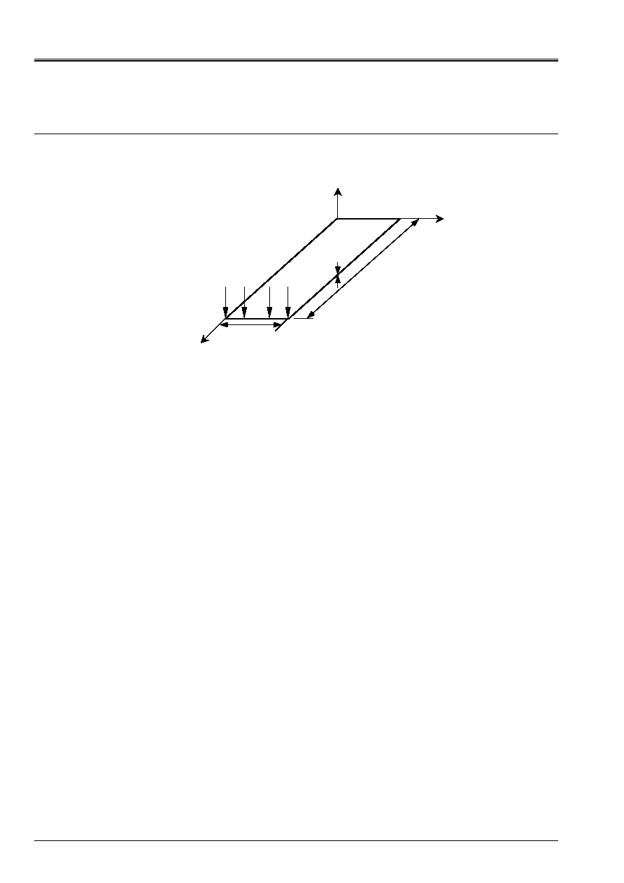
1.1 Geometry
X
y
O
With
B
C
L
L
F
H
Z
L= length 100 m, width l=10 Mr.
Thickness: case 1 h=10 m, cases 2 h=1 m, cases 3 h=0.1 m, cases 4 h=0.05 m, cases 5 h=0.02 m
1.2
Material properties
E = 2. 10
11
AP
= 0.3
1.3
Boundary conditions and loadings
Embedded on side OC: U = v = W = 0,
X
=
y
=
Z
= 0
At end AB, a load uniformly distributed of resultant:
Force parallel with axis Z; F
Z
= 1 NR

Code_Aster
®
Version
7.2
Titrate:
SSLS124 - Beam in bending with various twinges
Date
:
06/11/03
Author (S):
J.M. PROIX, S. BAGUET
Key
:
V3.03.124-A
Page:
3/8
Manual of Validation
V3.03 booklet: Linear statics of the plates and hulls
HT-66/03/008/A
2
Reference solution
2.1
Method of calculation used for the reference solution
The results of reference are obtained by the theory of the elastic beams.
Vertical displacement at end AB is given by:
Uy = F.L
3
/3.E.I
Z
With
I
Z
= l.h
3
/12
2.2
Results of reference
Displacement of points A and B following Z.
Code_Aster
®
Version
7.2
Titrate:
SSLS124 - Beam in bending with various twinges
Date
:
06/11/03
Author (S):
J.M. PROIX, S. BAGUET
Key
:
V3.03.124-A
Page:
4/8
Manual of Validation
V3.03 booklet: Linear statics of the plates and hulls
HT-66/03/008/A
3 Modeling
With
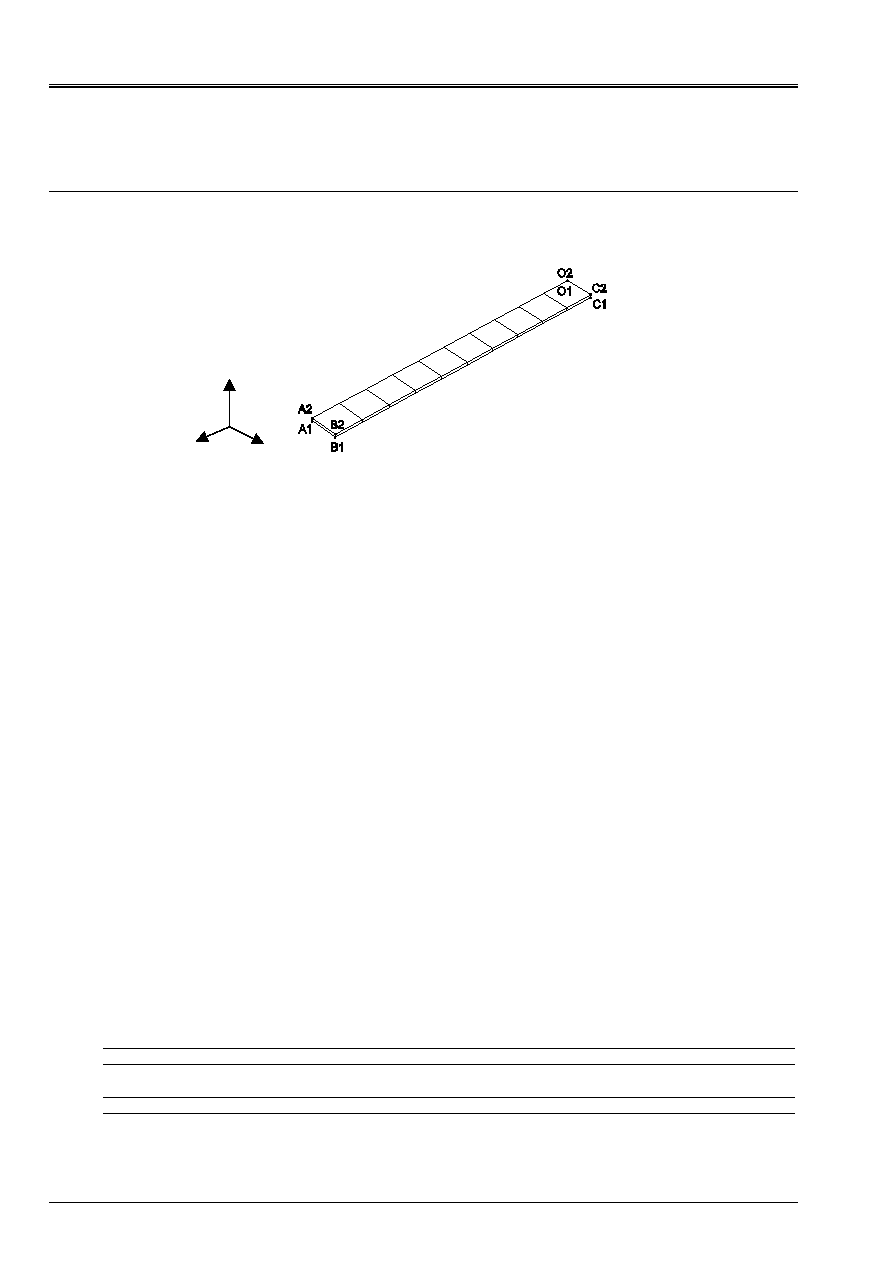
3.1
Characteristics of modeling
Element SHB8
Cutting: a regular mesh is considered in this modeling.
Regular mesh:
10 meshs SHB8: 1 according to the width, 10 according to the length, 1 according to the thickness
thickness: case 1 h=10 m, cases 2 h=1 m, cases 3 h=0.1 m, cases 4 h=0.05 m, cases 5 h=0.02 m
Boundary conditions:
In all the nodes on the side OC: following locked displacement
X
in C1: following locked displacement
Y
and
Z
in C2: following locked displacement
Y
in O1: following locked displacement
Z
Loading:
in A2: nodal force according to
X
:
FX = 0,5
in B2: nodal force according to
Y
:
FY = 0,5
Name of the nodes:
Not O1
N40
Not O2
N44
Not A1
N03
Not A2
N01
Not B1
N04
Not B2
N02
Not C1
N43
Not C2
N39
3.2
Characteristics of the mesh
A number of nodes: 44
A number of meshs and types: 11 SHB8
In the case of the regular mesh, each element is a perfect square on side length 10m
3.3 Functionalities
tested
Controls
MODI_MAILLAGE ORIE_SHB8
GROUP_MA
ALL
AFFE_CHAR_MECA DDL_IMPO
FORCE_NODALE
GROUP_NO
GROUP_NO
AFFE_MODELE AFFE
MODELING
:
SHB8
MECA_STATIQUE SOLVEUR
NPREC
Z
y
X

Code_Aster
®
Version
7.2
Titrate:
SSLS124 - Beam in bending with various twinges
Date
:
06/11/03
Author (S):
J.M. PROIX, S. BAGUET
Key
:
V3.03.124-A
Page:
5/8
Manual of Validation
V3.03 booklet: Linear statics of the plates and hulls
HT-66/03/008/A
4
Results of modeling A
4.1 Values
tested
Regular mesh:
Thickness
Not
Size in unit
Reference
Aster
% difference
Case 1
A2
displacement W (m)
2. 10
9
2.008 10
9
+0.41
H = 10m
B2
displacement W (m)
2. 10
9
2.008 10
9
+0.41
Case 2
A2
displacement W (m)
2. 10
6
1.995 10
6
0.27
H = 1m
B2
displacement W (m)
2. 10
6
1.995 10
6
0.27
Case 3
A2
displacement W (m)
2. 10
3
1.994 10
3
0.28
H = 0.1m
B2
displacement W (m)
2. 10
3
1.994 10
3
0.28
Case 4
A2
displacement W (m)
1.6 10
2
1.597 10
2
0.2
H = 0.05m
B2
displacement W (m)
1.6 10
2
1.595 10
2
0.3
Case 5
A2
displacement W (m)
0.25
2.380 10
1
+4.8
H = 0.02m
B2
displacement W (m)
0.25
2.416 10
1
+3.4
4.2 Remarks
For the strong twinges, (case 3, 4, 5), it is necessary to increase the number of decimals
lost with the resolution, using the key word
NPREC
. This does not prevent from obtaining a correct solution
(at least for cases 3 and 4).
The twinges are (ratio H/min (I, L/10)) :
Case 1: 1
Case 2: 0.1
Case 3: 0.01
Case 4: 0.005
Case 5: 0.002
Code_Aster
®
Version
7.2
Titrate:
SSLS124 - Beam in bending with various twinges
Date
:
06/11/03
Author (S):
J.M. PROIX, S. BAGUET
Key
:
V3.03.124-A
Page:
6/8
Manual of Validation
V3.03 booklet: Linear statics of the plates and hulls
HT-66/03/008/A
5 Modeling
B
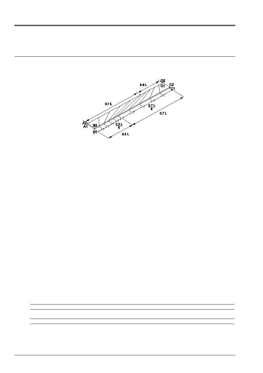
5.1
Characteristics of modeling
Element SHB8
Cutting: an irregular mesh is considered in this modeling.
Not-regular mesh:
10 meshs SHB8: 1 according to the width, 10 according to the length, 1 according to the thickness
thickness: case 1 h=10 m, cases 2 h=1 m, cases 3 h=0.1 m, cases 4 h=0.05 m, cases 5 h=0.02 m
Boundary conditions:
In all the nodes on the side OC: following locked displacement
X
in C1: following locked displacement
Y
and
Z
in C2: following locked displacement
Y
in O1: following locked displacement
Z
Loading:
in A2: nodal force according to
X
:
FX = 0,5
in B2: nodal force according to
Y
:
FY = 0,5
Names of the nodes:
Not O1
N40
Not O2
N44
Not A1
N03
Not A2
N01
Not B1
N04
Not B2
N02
Not C1
N43
Not C2
N39
5.2
Characteristics of the mesh
A number of nodes: 44
A number of meshs and types: 11 SHB8
5.3 Functionalities
tested
Controls
MODI_MAILLAGE ORIE_SHB8
GROUP_MA
ALL
AFFE_CHAR_MECA DDL_IMPO
FORCE_NODALE
GROUP_NO
GROUP_NO
AFFE_MODELE AFFE
MODELING
:
SHB8
MECA_STATIQUE SOLVEUR
NPREC

Code_Aster
®
Version
7.2
Titrate:
SSLS124 - Beam in bending with various twinges
Date
:
06/11/03
Author (S):
J.M. PROIX, S. BAGUET
Key
:
V3.03.124-A
Page:
7/8
Manual of Validation
V3.03 booklet: Linear statics of the plates and hulls
HT-66/03/008/A
6
Results of modeling B
6.1 Values
tested
Not-regular mesh:
Thickness
Not
Size in unit
Reference
Aster
% difference
Case 1
A2
displacement W (m)
2. 10
9
1.939 10
9
3.03
H = 10m
B2
displacement W (m)
2. 10
9
1.921 10
9
3.94
Case 2
A2
displacement W (m)
2. 10
6
1.925 10
6
3.73
H = 1m
B2
displacement W (m)
2. 10
6
1.907 10
6
4.64
Case 3
A2
displacement W (m)
2. 10
3
1.925 10
3
3.75
H = 0.1m
B2
displacement W (m)
2. 10
3
1.907 10
3
4.65
Case 4
A2
displacement W (m)
1.6 10
2
1.542 10
2
3.60
H = 0.05m
B2
displacement W (m)
1.6 10
2
1.528 10
2
4.51
Case 5
A2
displacement W (m)
0.25
2.479 10
1
0.83
H = 0.02m
B2
displacement W (m)
0.25
2.45710
1
1.72
6.2 Remarks
For the strong twinges, (case 3, 4, 5), it is necessary to increase the number of decimals
lost with the resolution, using the key word
NPREC
. This does not prevent from obtaining a correct solution
(at least for cases 3 and 4).
The twinges are (ratio H/min (I, L/10)) :
Case 1: 1
Case 2: 0.1
Case 3: 0.01
Case 4: 0.005
Case 5: 0.002

Code_Aster
®
Version
7.2
Titrate:
SSLS124 - Beam in bending with various twinges
Date
:
06/11/03
Author (S):
J.M. PROIX, S. BAGUET
Key
:
V3.03.124-A
Page:
8/8
Manual of Validation
V3.03 booklet: Linear statics of the plates and hulls
HT-66/03/008/A
7
Summary of the results
In the case of the regular mesh, from good solutions are obtained. The quality of the solution declines
nevertheless when the twinge of the element (side ratio/thickness) reached 200.
In the case of the not-regular mesh, whatever the twinge of the element, one tends to underestimate
the rigidity of the beam from approximately 4%.
This test can be supplemented by a modeling 3D and to be applied to the elements of
COQUE_3D
MEC3QU9H like with elements DKT.