
Code_Aster
®
Version
5.0
Titrate:
SSLS502 - Orthotropic cylinder subjected to a line of load
Date:
19/09/02
Author (S):
P. MASSIN, F. LEBOUVIER
Key
:
V3.03.502-A
Page:
1/18
Manual of Validation
V3.03 booklet: Linear statics of the hulls and the plates
HT-66/02/001/A
Organization (S):
EDF/AMA, DeltaCAD
Manual of Validation
V3.03 booklet: Linear statics of the hulls and the plates
Document: V3.03.502
SSLS502 - Orthotropic cylinder subjected to a line
of load
Summary:
This test represents quasi-static calculation, of a short orthotropic cylinder and an orthotropic long cylinder
subjected to a line of load. Their ends, the cylinders rest on rigid diaphragms. This case
test makes it possible to validate modeling finite elements DST with meshs TRIA3 and QUAD4, a material
homogeneous orthotropic.
Displacements and the efforts obtained are compared with a reference solution experimental like to
an analytical solution.
Code_Aster
®
Version
5.0
Titrate:
SSLS502 - Orthotropic cylinder subjected to a line of load
Date:
19/09/02
Author (S):
P. MASSIN, F. LEBOUVIER
Key
:
V3.03.502-A
Page:
2/18
Manual of Validation
V3.03 booklet: Linear statics of the hulls and the plates
HT-66/02/001/A
1
Problem of reference
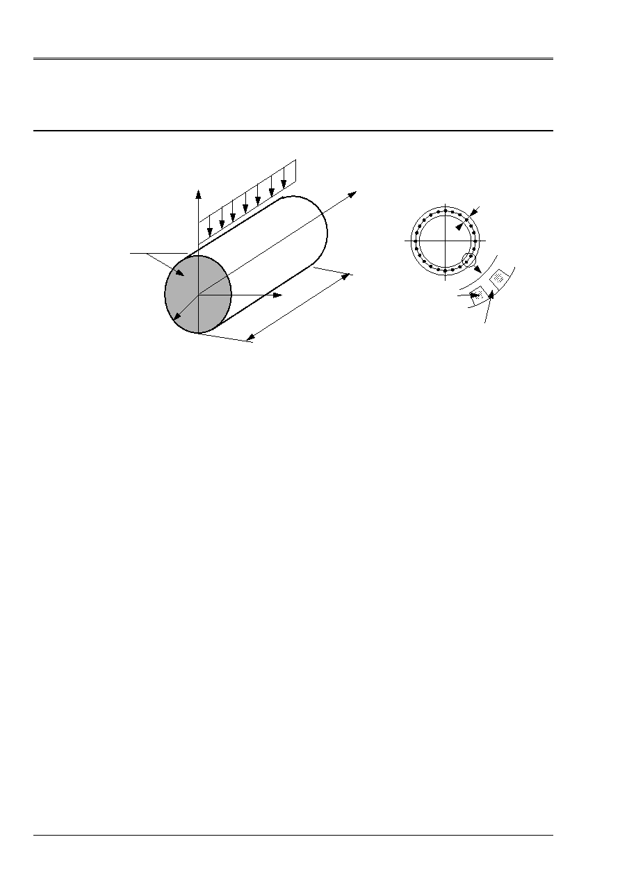
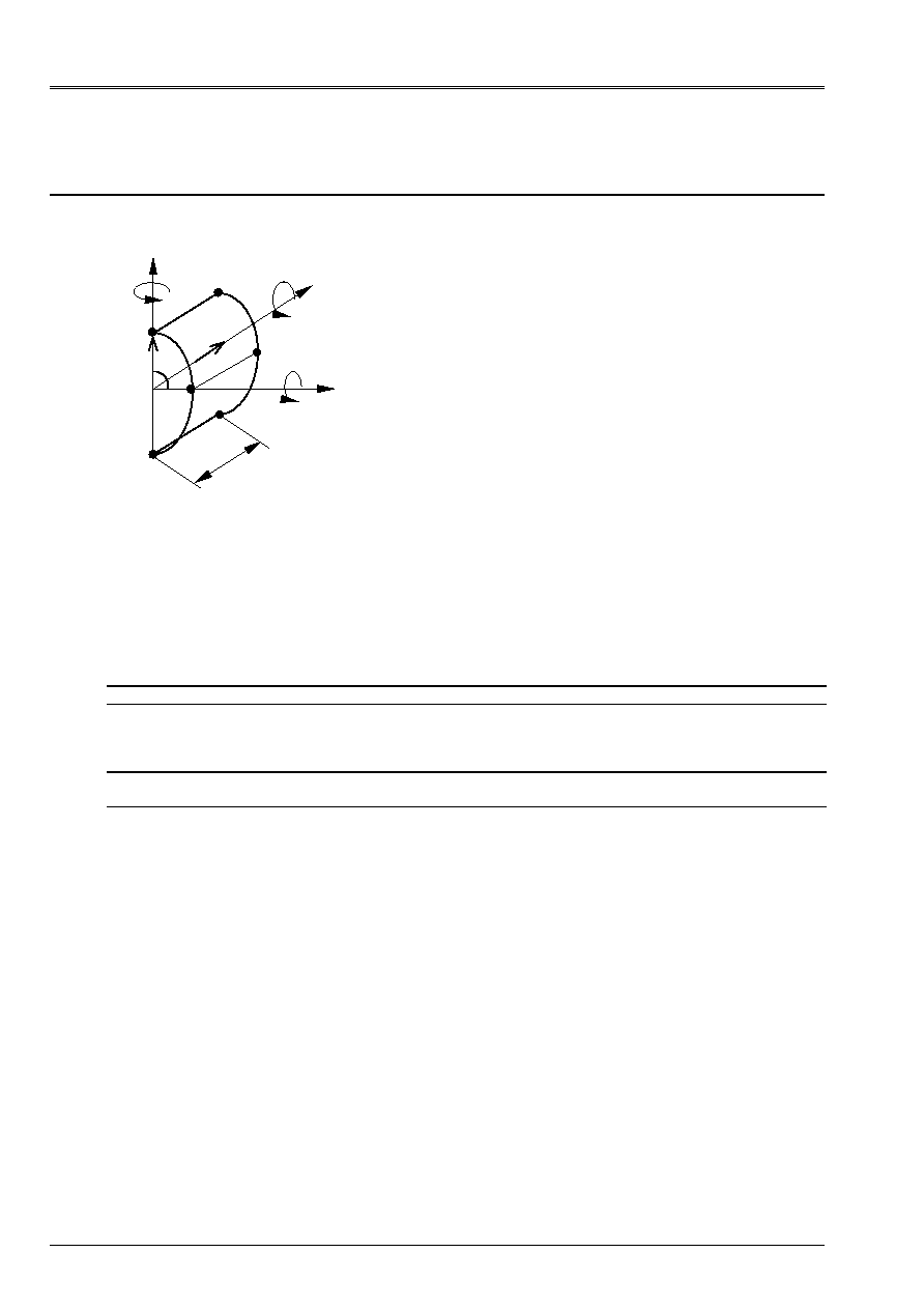
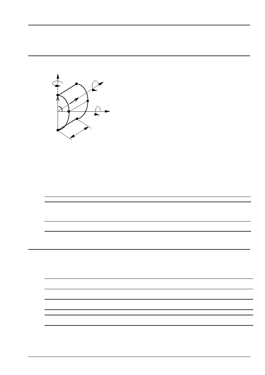
1.1 Geometry
X
Y
Z
Q
R
L = 0.560 m
R = 0.13595 m
L
Steel yarn
H
Plastic
(acrylic resin)
H = 0.0061 m
Q = 2357.143 NR/m
Plastic
(acrylic resin)
Diaphragm
rigid
L = 2.465 m
R = 0.13595 m
H = 0.0061 m
Q = 896.552 NR/m
roll short:
roll long:
1.2
Properties of material
The material constituting the cylinder is homogeneous orthotropic. The axes of orthotropism correspond
with the curvilinear directions X and Y.
[
]
[]
H
H H
membrane
=
;
[
]
[]
H
membrane bending
-
=
0
;
[
]
[]
H
H H
bending
=
3
12
/
H
11
= 3.0644 X 10
9
NR/m ²; H
12
= 1.1048 X 10
9
NR/m ²; H
13
= 0
H
22
= 18.597 X 10
9
NR/m ²; H
23
= 0
; H
33
=1.250 X 10
9
NR/m ²
1.3
Boundary conditions and loadings
- CL: The ends of the cylinder rest on rigid diaphragms
- Modelings A and b: Forces per unit of length: Q = - 2357.143 NR/m
- Modelings C and D: Force per unit of length: Q = - 896.552. NR/m
1.4 Conditions
initial
Without object

Code_Aster
®
Version
5.0
Titrate:
SSLS502 - Orthotropic cylinder subjected to a line of load
Date:
19/09/02
Author (S):
P. MASSIN, F. LEBOUVIER
Key
:
V3.03.502-A
Page:
3/18
Manual of Validation
V3.03 booklet: Linear statics of the hulls and the plates
HT-66/02/001/A
2
Reference solution
2.1
Method of calculation used for the reference solution
We will use for this test two reference solutions, one experimental, resulting from work from
Schwaighofer and Microys [bib2], the other drawn from work of Batoz in theory of the deep hulls
[bib1].
2.2
Results of reference
The results of reference are as follows:
Roll (A and B) short
Batoz [bib1]
Experiment [bib2]
Displacement W at the point F
0.35 10
4
m 0.6
10
4
m
Displacement W at the point C
0.7 10
3
m
0.6 10
3
m
Displacement W at the point D
0.25 10
4
m
0.1 10
3
m
Stress
xx
at the point F
0.35 MPa
0.325 MPa
Stress
yy
at the point F
0.50 MPa
0.60 MPa
Roll long (C and D)
Batoz [bib1]
Experiment [bib2]
Displacement W at the point F
1.32 10
3
m
1.35 10
3
m
Displacement W at the point C
2.45 10
3
m
2.46 10
3
m
Displacement W at the point D
0.35 10
3
m
0.51 10
3
m
Stress
xx
at the point F
1.68 MPa
1.9 MPa
Stress
yy
at the point F
1.8 MPa
1.55 MPa
2.3
Uncertainties on the solution
~ 5% with regard to the solution of Batoz, undoubtedly much more - ~30% - for the solution
experimental.
2.4 References
bibliographical
[1]
BATOZ J.L., DHATT G.: Modeling of the structures by finite elements, Flight 3, Hulls,
HERMES.
[2]
SCHWAIGHOFER J., MICROYS H.F.: Orthotropic Cylindrical shells under line load, Newspaper
off applied Mechanics, June 1979, Flight 46.
[3]
GEOFFROY P., Development and evaluation of a finite element for the non-linear analysis
statics and dynamics of thin hulls, Thesis of Doctor Engineer, University of
Technology of Compiegne, 27/04/83.
Code_Aster
®
Version
5.0
Titrate:
SSLS502 - Orthotropic cylinder subjected to a line of load
Date:
19/09/02
Author (S):
P. MASSIN, F. LEBOUVIER
Key
:
V3.03.502-A
Page:
4/18
Manual of Validation
V3.03 booklet: Linear statics of the hulls and the plates
HT-66/02/001/A
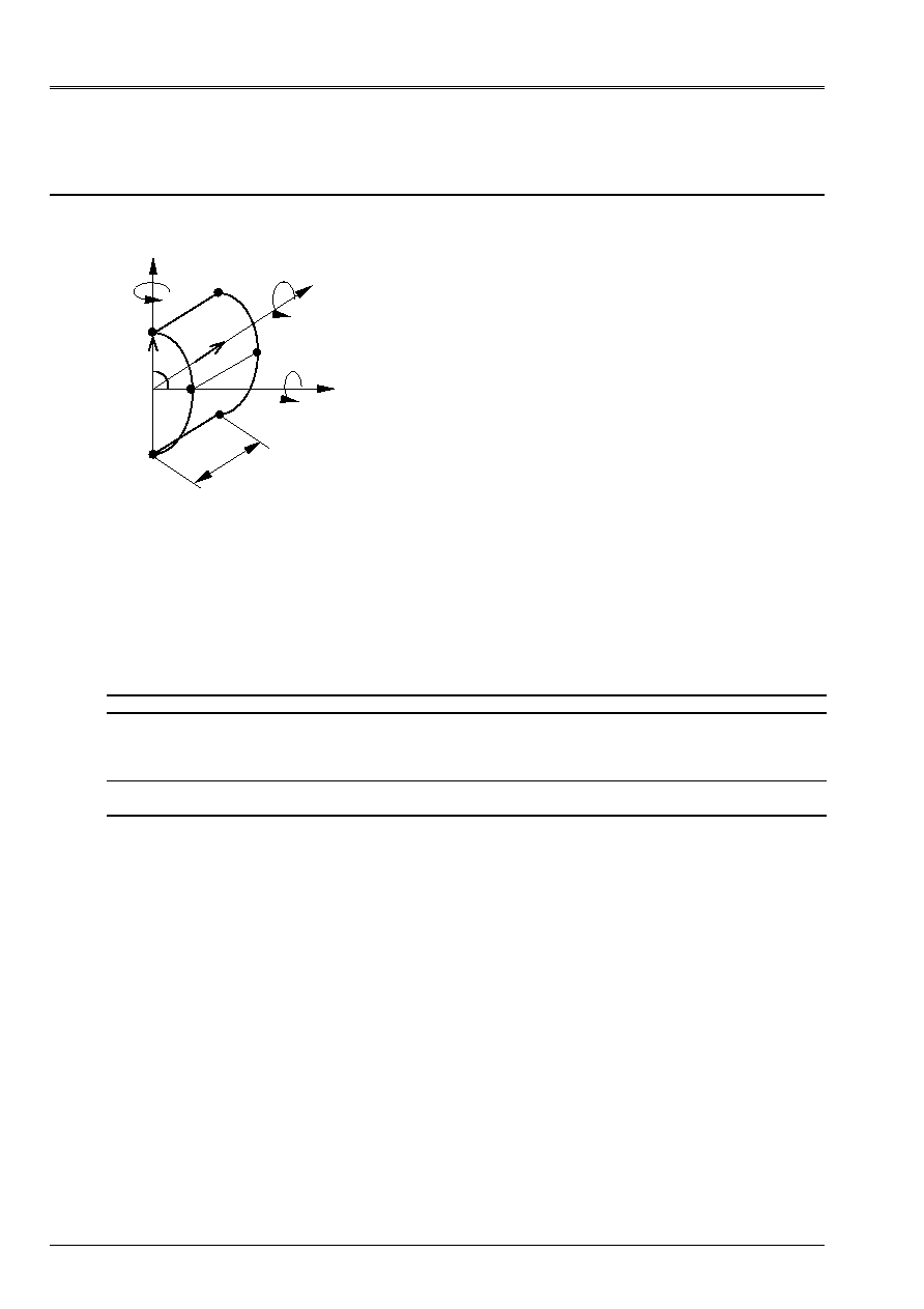
3 Modeling
With
3.1
Characteristics of modeling
Z
y
D
DST modeling (one modelizes a half rolls)
- 8 elements in the circumferential direction
- 12 elements in the longitudinal direction
X
Y
Z
C
B
With
F
E
L/2
Z
X
- Boundary conditions: Side AB:
U = W =
y
=0
- Conditions of symmetry: Sides AD and BC: U =
y
=
Z
= 0
Side cd.:
v =
X
=
Z
= 0
- Force per unit of length side BC: Q/2 = 1178.5715 NR/m
R, W
3.2
Characteristics of the mesh
A number of nodes: 224
A number of meshs and type: 192 QUAD4
3.3 Functionalities
tested
Controls Key word
factor
Key word
AFFE_MODELE
AFFE
“DST”
DEFI_MATERIAU
ELAS_COQUE
MEMB_L
MEMB_LT
MEMB_T
MEMB_G_LT
FLEX_L
FLEX_LT
FLEX_T
FLEX_G_LT
CISA_L
CISA_T
AFFE_CARA_ELEM
HULL
THICK
ANGL_REP
AFFE_CHAR_MECA
FORCE_ARETE
FZ
Code_Aster
®
Version
5.0
Titrate:
SSLS502 - Orthotropic cylinder subjected to a line of load
Date:
19/09/02
Author (S):
P. MASSIN, F. LEBOUVIER
Key
:
V3.03.502-A
Page:
5/18
Manual of Validation
V3.03 booklet: Linear statics of the hulls and the plates
HT-66/02/001/A
4
Results of modeling A
4.1 Values
tested
Identification Reference
numerical
[bib1]
Reference
expériementale
[bib2]
Aster %
differences
Displacement W at the point F
0.35x10
4
m 0.6
10
4
m 0.373
10
4
m 6.703 [bib1]
37.757 [bib2]
Displacement W at the point C
0.7 10
3
m
0.6 10
3
m
0.721 x10
3
3.033 [bib1]
20.205 [bib2]
Displacement W at the point D
0.25 10
4
m
0.1 10
3
m
0.369 10
4
47.689 [bib1]
- 63.078 [bib2]
Stress SIXX at the point F
0.350 MPa
0.325 MPa
0.480 MPa
37.339 [bib1]
47.904 [bib2]
Stress SIYY at the point F
0.500 MPa
0.600 MPa
0.490 MPa
- 1.901 [bib1]
- 18.259 [bib2]
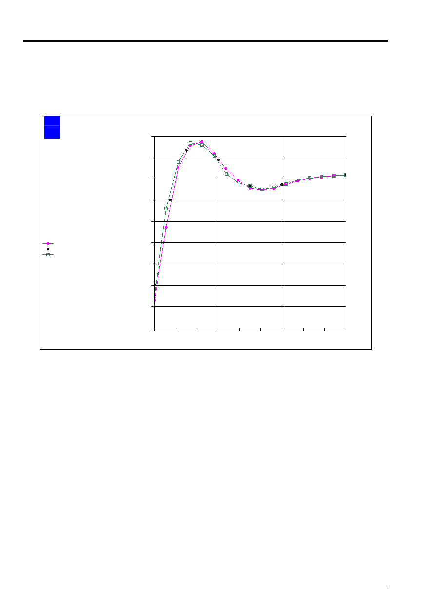
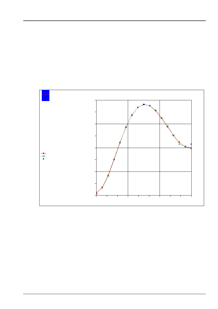
4.2
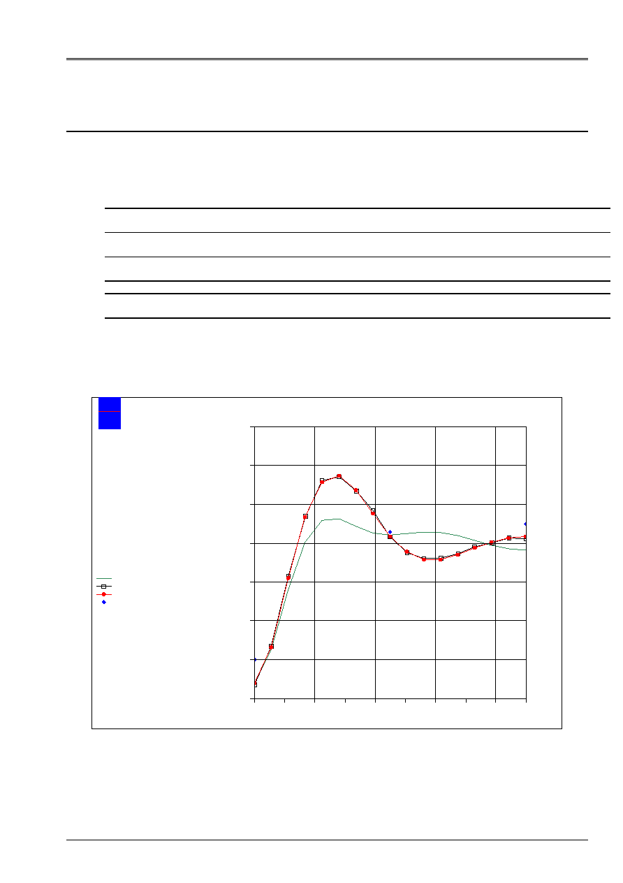
Value of normal displacement W along CD
angle (deg)
D
E
p
L
acemen
T (
mm)
EDF
Electricity
from France
Mechanical department and Numerical Models
W according to the angle along CD
agraf 19/04/2001 (c) EDF/DER 1992-1999
W (total reference mark)
W normal Batoz reference
W normal
W normal experimental
ROLL SHORT ORTHOTROPIC
DKT 8 X 12 QUAD4
- 0.8
- 0.6
- 0.4
- 0.2
0.0
0.2
0.4
0.6
0
20
40
60
80
100
120
140
160
180
One can note that beyond the variations observed on the points tested C, F, D, normal displacement
calculated along CD is close to the solution in theory “deep hulls” adopted by Batoz
[bib1]. One can charge the errors relating to the points F and D to the low value of the displacement (of
the command of 10
5
m).
Code_Aster
®
Version
5.0
Titrate:
SSLS502 - Orthotropic cylinder subjected to a line of load
Date:
19/09/02
Author (S):
P. MASSIN, F. LEBOUVIER
Key
:
V3.03.502-A
Page:
6/18
Manual of Validation
V3.03 booklet: Linear statics of the hulls and the plates
HT-66/02/001/A
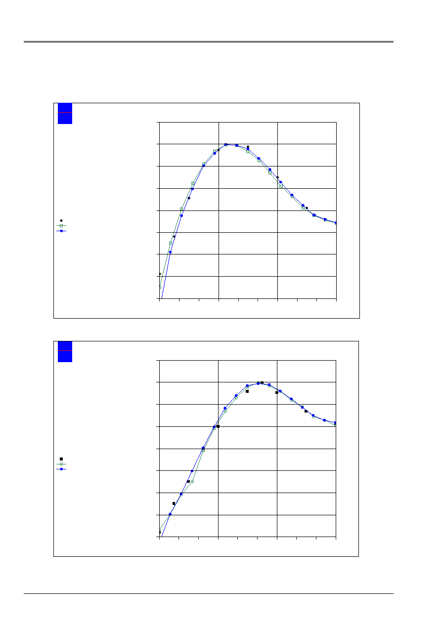
4.3
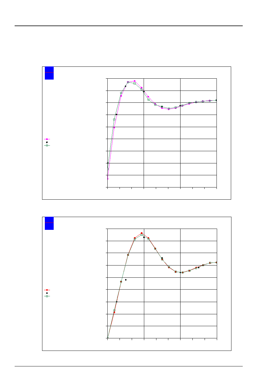
Value of the stresses along CD
angle (deg)
Co
N
T
R
has
in
your
(
M
P
has
)
EDF
Electricity
from France
Mechanical department and Numerical Models
Sigma XX along CD
agraf 05/06/2001 (c) EDF/DER 1992-1999
sigma XX
Experimental ref. Schwaighofer/Microys
Ref. Batoz
ROLL SHORT ORTHOTROPIC
DKT 8 X 12 QUAD4
- 7
- 6
- 5
- 4
- 3
- 2
- 1
0
1
2
0
20
40
60
80
100
120
140
160
180
angle (deg)
Co
N
T
R
has
in
your
(
M
P
has
)
EDF
Electricity
from France
Mechanical department and Numerical Models
sigma YY along CD
agraf 05/06/2001 (c) EDF/DER 1992-1999
sigma YY
Experimental ref. Schwaighofer/Microys
Ref. Batoz
ROLL SHORT ORTHOTROPIC
DKT 8 X 12 QUAD4
- 6
- 5
- 4
- 3
- 2
- 1
0
1
2
3
0
20
40
60
80
100
120
140
160
180

Code_Aster
®
Version
5.0
Titrate:
SSLS502 - Orthotropic cylinder subjected to a line of load
Date:
19/09/02
Author (S):
P. MASSIN, F. LEBOUVIER
Key
:
V3.03.502-A
Page:
7/18
Manual of Validation
V3.03 booklet: Linear statics of the hulls and the plates
HT-66/02/001/A
One can note that the stresses calculated along CD are overall in agreement with the solution
in theory “deep hulls” adopted by Batoz [bib1].
4.4 Remarks
·
The values of coefficients CISA_L and CISA_T are not available. Like the structure
is thin (H/R=0.045), one supposes that the effects of transverse shearing are negligible,
we thus imposed CISA_L=CISA_T=10
10
.
·
Displacement W normal (figure of [§4.2]) is expressed in the local cylindrical reference mark (R,
, Z), it
acts of normal displacement to the element of hull. Displacement W tested with [§4.1] is as for
he expressed in the total reference mark (displacement following Z).
Code_Aster
®
Version
5.0
Titrate:
SSLS502 - Orthotropic cylinder subjected to a line of load
Date:
19/09/02
Author (S):
P. MASSIN, F. LEBOUVIER
Key
:
V3.03.502-A
Page:
8/18
Manual of Validation
V3.03 booklet: Linear statics of the hulls and the plates
HT-66/02/001/A
5 Modeling
B
5.1
Characteristics of modeling
Z
y
D
DST modeling (one modelizes a half rolls)
- 8 elements in the circumferential direction
- 12 elements in the longitudinal direction
X
Y
Z
C
B
With
F
E
L/2
Z
X
- Boundary conditions: Side AB:
U = W =
y
=0
- Conditions of symmetry: Sides AD and BC: U =
y
=
Z
= 0
Side cd.:
v =
X
=
Z
= 0
- Force per unit of length side BC: Q/2 = 1178.5715 NR/m
R, W
5.2
Characteristics of the mesh
A number of nodes: 224
A number of meshs and type: 384 TRIA3
5.3 Functionalities
tested
Controls Key word
factor
Key word
AFFE_MODELE
AFFE
“DST”
DEFI_MATERIAU
ELAS_COQUE
MEMB_L
MEMB_LT
MEMB_T
MEMB_G_LT
FLEX_L
FLEX_LT
FLEX_T
FLEX_G_LT
CISA_L
CISA_T
AFFE_CARA_ELEM
HULL
THICK
ANGL_REP
AFFE_CHAR_MECA
FORCE_ARETE
FZ

Code_Aster
®
Version
5.0
Titrate:
SSLS502 - Orthotropic cylinder subjected to a line of load
Date:
19/09/02
Author (S):
P. MASSIN, F. LEBOUVIER
Key
:
V3.03.502-A
Page:
9/18
Manual of Validation
V3.03 booklet: Linear statics of the hulls and the plates
HT-66/02/001/A
6
Results of modeling B
6.1 Values
tested
Identification Reference
[bib1]
Reference
[bib2]
Aster %
differences
Displacement W at the point F
0.35 10
- 4
m 0.6
10
4
m 0.383
10
4
9.571 [bib1]
36.084 [bib2]
Displacement W at the point C
0.7 10
- 3
m 0.6
10
3
m
7.138 10
4
1.985 [bib1]
18.982 [bib2]
Displacement W at the point D
0.25 10
- 4
m 0.1
10
3
m
0.350 10
4
40.368 [bib1]
64.908 [bib2]
Stress SIXX at the point F
0.350 MPa
0.325 MPa
0.470 MPa
34.348 [bib1]
44.682 [bib2]
Stress SIYY at the point F
0.500 MPa
0.600 MPa
0.400 MPa
19.929 [bib1]
33.274 [bib2]
6.2 Remarks
·
The values of coefficients CISA_L and CISA_T are not available. Like the structure
is thin (H/R=0.045), one supposes that the effects of transverse shearing are negligible,
we thus imposed CISA_L=CISA_T=10
10
.
·
Displacement W normal is expressed in the local cylindrical reference mark (R,
, Z), it acts of
normal displacement with the element of hull.
6.3
Value of normal displacement along CD
The results obtained with a mesh TRIA3 are very close to those obtained by the mesh
QUAD4.
Code_Aster
®
Version
5.0
Titrate:
SSLS502 - Orthotropic cylinder subjected to a line of load
Date:
19/09/02
Author (S):
P. MASSIN, F. LEBOUVIER
Key
:
V3.03.502-A
Page:
10/18
Manual of Validation
V3.03 booklet: Linear statics of the hulls and the plates
HT-66/02/001/A
6.4
Value of the stresses along CD
angle (deg)
Co
N
T
R
has
in
your
(
M
P
has
)
EDF
Electricity
from France
Mechanical department and Numerical Models
Sigma XX along CD
agraf 05/06/2001 (c) EDF/DER 1992-1999
sigma XX
Experimental ref. Schwaighofer/Microys
Ref. Batoz
ROLL SHORT ORTHOTROPIC
DKT 8 X 12 TRIA3
- 7
- 6
- 5
- 4
- 3
- 2
- 1
0
1
2
0
20
40
60
80
100
120
140
160
180
Code_Aster
®
Version
5.0
Titrate:
SSLS502 - Orthotropic cylinder subjected to a line of load
Date:
19/09/02
Author (S):
P. MASSIN, F. LEBOUVIER
Key
:
V3.03.502-A
Page:
11/18
Manual of Validation
V3.03 booklet: Linear statics of the hulls and the plates
HT-66/02/001/A
angle (deg)
Co
N
T
R
has
in
your
(
M
P
has
)
EDF
Electricity
from France
Mechanical department and Numerical Models
sigma YY along CD
agraf 05/06/2001 (c) EDF/DER 1992-1999
sigma YY
Experimental ref. Schwaighofer/Microys
Ref. Batoz
ROLL SHORT ORTHOTROPIC
DKT 8 X 12 TRIA3
- 6
- 5
- 4
- 3
- 2
- 1
0
1
2
3
0
20
40
60
80
100
120
140
160
180
The profiles of the stresses obtained by modeling B with TRIA3 are as a whole
near to the solutions of Batoz.
Code_Aster
®
Version
5.0
Titrate:
SSLS502 - Orthotropic cylinder subjected to a line of load
Date:
19/09/02
Author (S):
P. MASSIN, F. LEBOUVIER
Key
:
V3.03.502-A
Page:
12/18
Manual of Validation
V3.03 booklet: Linear statics of the hulls and the plates
HT-66/02/001/A
7 Modeling
C
7.1
Characteristics of modeling
Z
y
D
DST modeling (one modelizes a half rolls)
- 8 elements in the circumferential direction
- 12 elements in the longitudinal direction
X
Y
Z
C
B
With
F
E
L/2
Z
X
- Boundary conditions: Side AB:
U = W =
y
=0
- Conditions of symmetry: Sides AD and BC: U =
y
=
Z
= 0
Side cd.:
v =
X
=
Z
= 0
- Force per unit of length side BC: Q/2 = 448.276 NR/m
R, W
7.2
Characteristics of the mesh
A number of nodes: 224
A number of meshs and type: 384 TRIA3
7.3 Functionalities
tested
Controls Key word
factor
Key word
AFFE_MODELE
AFFE
“DST”
DEFI_MATERIAU
ELAS_COQUE
MEMB_L
MEMB_LT
MEMB_T
MEMB_G_LT
FLEX_L
FLEX_LT
FLEX_T
FLEX_G_LT
CISA_L
CISA_T
AFFE_CARA_ELEM
HULL
THICK
ANGL_REP
AFFE_CHAR_MECA
FORCE_ARETE
FZ
8
Results of modeling C
8.1 Values
tested
Identification Reference
numerical
[bib1]
Reference
experimental
[bib2]
Aster %
difference
Displacement W at the point F
1.325 10
3
m
1.35 10
3
m
1.327 10
3
m
0.154 [bib1]
1.701 [bib2]
Displacement W at the point C
2.45 10
3
m
2.46 10
3
m
2.379 10
3
m
2.881 [bib1]
3.275 [bib2]
Displacement W at the point D
0.51 10
3
m
0.35 10
3
m
0.529 10
3
m
3.859 [bib1]
51.337 [bib2]
Stress SIXX at the point F
1.68 MPa
1.9 MPa
1.643 MPa
2.155 [bib1]
13.484 [bib2]
Stress SIYY at the point F
1.8 MPa
1.55 MPa
1.782 MPa
0.986 [bib1]
14.984 [bib2]
Code_Aster
®
Version
5.0
Titrate:
SSLS502 - Orthotropic cylinder subjected to a line of load
Date:
19/09/02
Author (S):
P. MASSIN, F. LEBOUVIER
Key
:
V3.03.502-A
Page:
13/18
Manual of Validation
V3.03 booklet: Linear statics of the hulls and the plates
HT-66/02/001/A
8.2 Remarks
·
The value of coefficients CISA_L and CISA_T are not available. As the structure is
thin (H/R=0.045), that the effects of transverse shearing are negligible, us are supposed
thus imposed CISA_L=CISA_T=10
10
.
·
Displacement W normal is expressed in the local cylindrical reference mark (R,
, Z), it acts of
normal displacement with the element of hull.
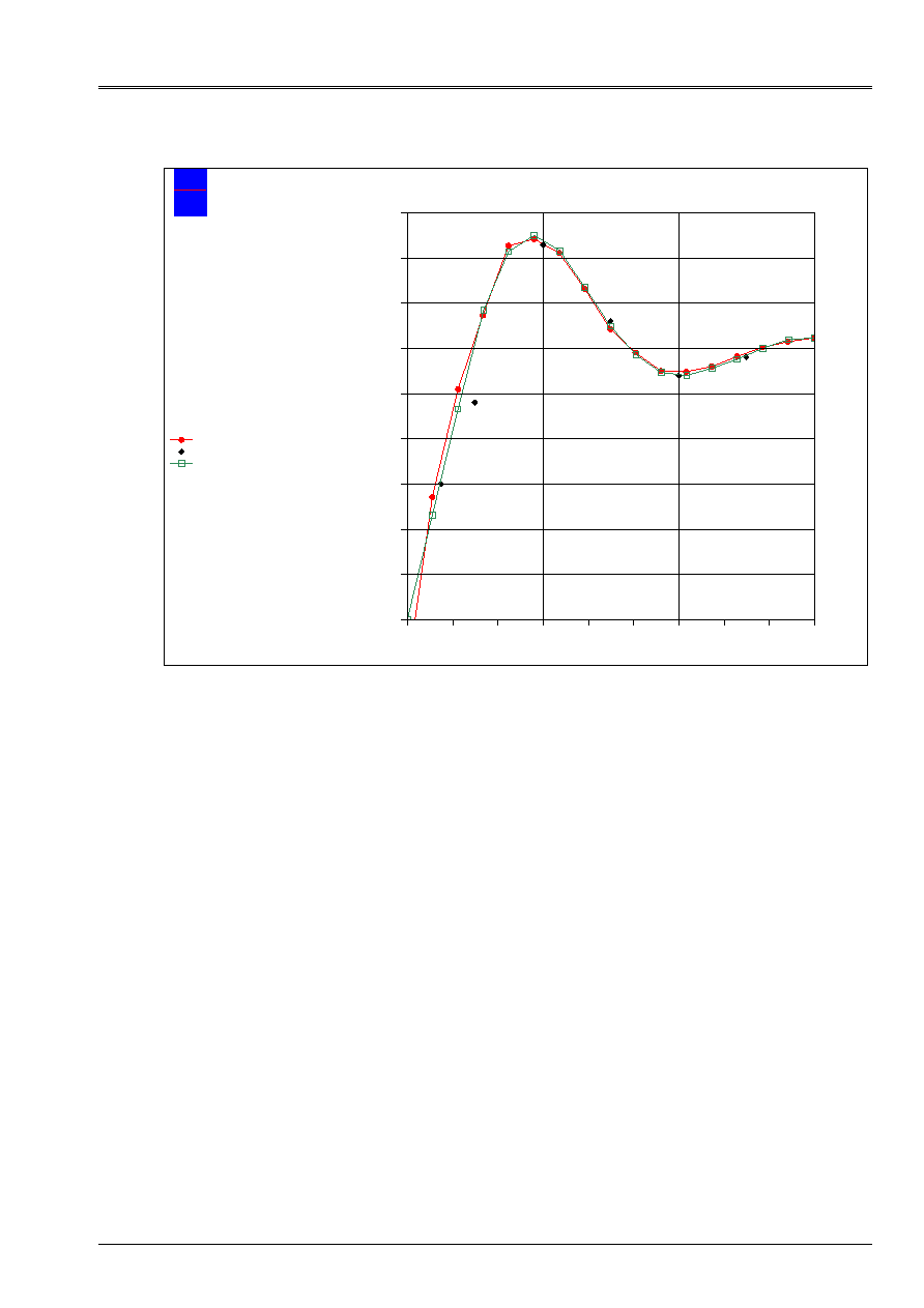
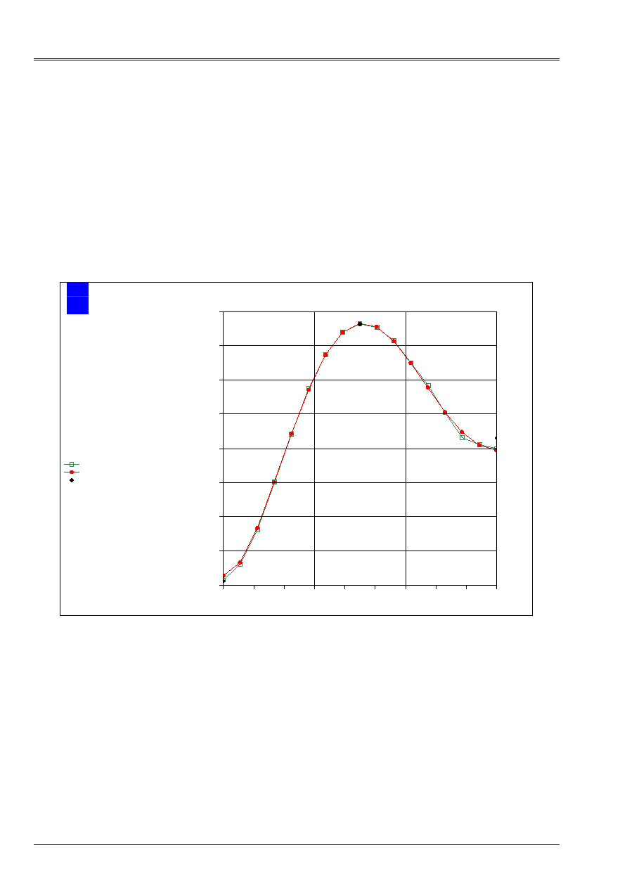
8.3
Value of normal displacement along CD
angle (deg)
D
E
p
L
acemen
T (
mm)
EDF
Electricity
from France
Mechanical department and Numerical Models
W according to the angle along CD
agraf 19/04/2001 (c) EDF/DER 1992-1999
W normal
W normal Batoz reference
W normal experimental
ROLL LONG ORTHOTROPIC
DKT 8 X 12 TRIA3
- 2.5
- 2.0
- 1.5
- 1.0
- 0.5
0.0
0.5
1.0
1.5
0
20
40
60
80
100
120
140
160
180
One can note that beyond the variation observed on the experimental value at the point D, displacement
normal calculated along CD is very close to the solution in adopted theory “deep hulls”
by Batoz [bib1].
Code_Aster
®
Version
5.0
Titrate:
SSLS502 - Orthotropic cylinder subjected to a line of load
Date:
19/09/02
Author (S):
P. MASSIN, F. LEBOUVIER
Key
:
V3.03.502-A
Page:
14/18
Manual of Validation
V3.03 booklet: Linear statics of the hulls and the plates
HT-66/02/001/A
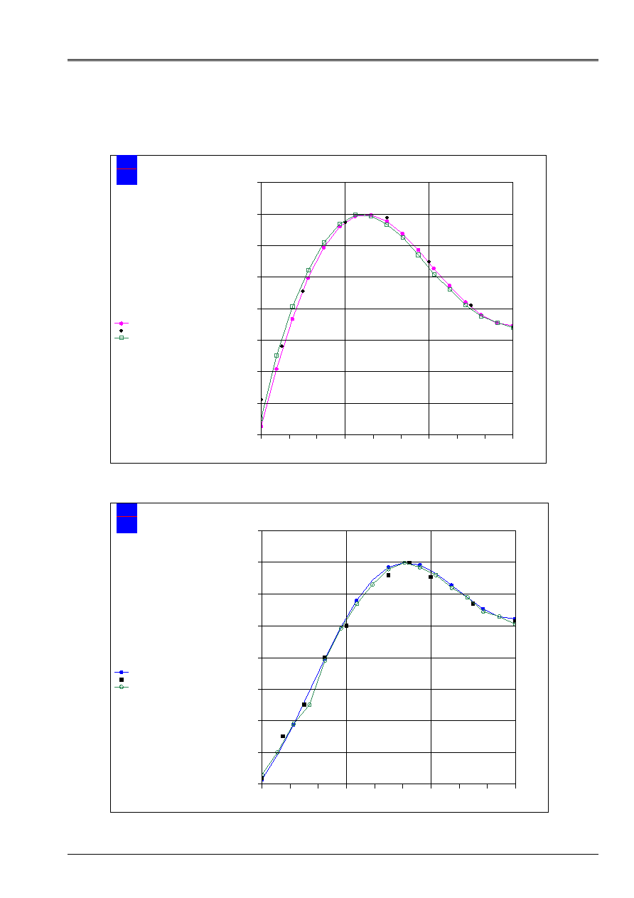
8.4
Value of the stresses along CD
angle (deg)
Co
N
T
R
has
in
your
(
M
P
has
)
EDF
Electricity
from France
Mechanical department and Numerical Models
Sigma XX along CD
agraf 05/06/2001 (c) EDF/DER 1992-1999
Experimental ref. Schwaighofer/Microys
Ref. Batoz
sigma XX
ROLL LONG ORTHOTROPIC
DKT 12 X 8 TRIA3
- 5
- 4
- 3
- 2
- 1
0
1
2
3
0
20
40
60
80
100
120
140
160
180
angle (deg)
Co
N
T
R
has
in
your
(
M
P
has
)
EDF
Electricity
from France
Mechanical department and Numerical Models
sigma YY along CD
agraf 05/06/2001 (c) EDF/DER 1992-1999
Experimental ref. Schwaighofer/Microys
Batoz theory “deep hulls”
sigma YY
ROLL LONG ORTHOTROPIC
DKT 12 X 8 TRIA3
- 5
- 4
- 3
- 2
- 1
0
1
2
3
0
20
40
60
80
100
120
140
160
180
The profiles of the stresses calculated by the code are overall in agreement with work of
Batoz.
Code_Aster
®
Version
5.0
Titrate:
SSLS502 - Orthotropic cylinder subjected to a line of load
Date:
19/09/02
Author (S):
P. MASSIN, F. LEBOUVIER
Key
:
V3.03.502-A
Page:
15/18
Manual of Validation
V3.03 booklet: Linear statics of the hulls and the plates
HT-66/02/001/A
9 Modeling
D
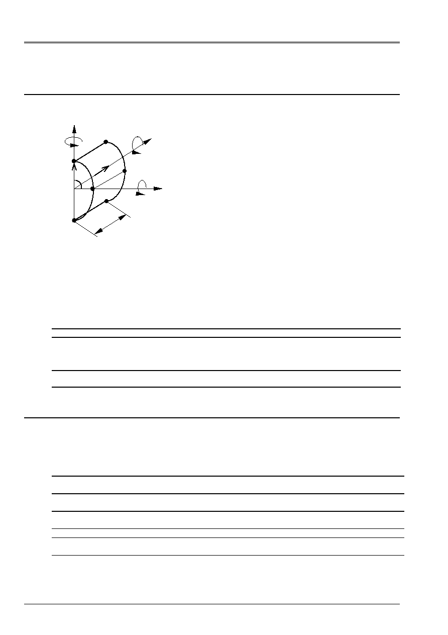
9.1
Characteristics of modeling
Z
y
D
DST modeling (one modelizes a half rolls)
- 8 elements in the circumferential direction
- 12 elements in the longitudinal direction
X
Y
Z
C
B
With
F
E
L/2
Z
X
- Boundary conditions: Side AB:
U = W =
y
=0
- Conditions of symmetry: Sides AD and BC: U =
y
=
Z
= 0
Side cd.:
v =
X
=
Z
= 0
- Force per unit of length side BC: Q/2 = 448.276 NR/m
R, W
9.2
Characteristics of the mesh
A number of nodes: 224
A number of meshs and type: 192 QUAD4
9.3 Functionalities
tested
Controls Key word
factor
Key word
AFFE_MODELE
AFFE
“DST”
DEFI_MATERIAU
ELAS_COQUE
MEMB_L
MEMB_LT
MEMB_T
MEMB_G_LT
FLEX_L
FLEX_LT
FLEX_T
FLEX_G_LT
CISA_L
CISA_T
AFFE_CARA_ELEM
HULL
THICK
ANGL_REP
AFFE_CHAR_MECA
FORCE_ARETE
FZ
10 Results of modeling D
10.1 Values
tested
Identification Reference
[bib1]
Reference
[bib2]
Aster %
difference
Displacement W at the point F
1.325 10
3
m
1.35 10
3
m
1.329 10
3
m
0.365 [bib1]
1.494 [bib2]
Displacement W at the point C
2.45 10
3
m
2.46 10
3
m
2.369 10
3
m
3.274 [bib1]
3.667 [bib2]
Displacement W at the point D
0.51 10
3
m
0.35 10
3
m
0.528 10
3
m
3.634 [bib1]
51.009 [bib2]
Stress SIXX at the point F
1.68 MPa
1.9 MPa
1.79 MPa
6.616 [bib1]
5.729 [bib2]
Stress SIYY at the point F
1.8 MPa
1.55 MPa
1.84 MPa
2.465 [bib1]
18.991 [bib2]
Code_Aster
®
Version
5.0
Titrate:
SSLS502 - Orthotropic cylinder subjected to a line of load
Date:
19/09/02
Author (S):
P. MASSIN, F. LEBOUVIER
Key
:
V3.03.502-A
Page:
16/18
Manual of Validation
V3.03 booklet: Linear statics of the hulls and the plates
HT-66/02/001/A
10.2 Remarks
·
The value of coefficients CISA_L and CISA_T are not available. As the structure is
thin (H/R=0.045), that the effects of transverse shearing are negligible, us are supposed
thus imposed CISA_L=CISA_T=10
10
.
·
Displacement W normal is expressed in the local cylindrical reference mark (R,
, Z), it acts of
normal displacement with the element of hull. Displacement W tested is that of the total reference mark
(displacement following Z).
10.3 Value of displacement along CD
angle (deg)
D
E
p
L
acemen
T (
mm)
EDF
Electricity
from France
Mechanical department and Numerical Models
W according to the angle along CD
agraf 19/04/2001 (c) EDF/DER 1992-1999
W normal Batoz reference
W normal
W normal experimental
ROLL LONG ORTHOTROPIC
DKT 8 X 12 QUAD4
- 2.5
- 2.0
- 1.5
- 1.0
- 0.5
0.0
0.5
1.0
1.5
0
20
40
60
80
100
120
140
160
180
One can note that beyond the variation observed on the experimental value at the point D, displacement
normal calculated along CD is very close to the solution in adopted theory “deep hulls”
by Batoz [bib1].
Code_Aster
®
Version
5.0
Titrate:
SSLS502 - Orthotropic cylinder subjected to a line of load
Date:
19/09/02
Author (S):
P. MASSIN, F. LEBOUVIER
Key
:
V3.03.502-A
Page:
17/18
Manual of Validation
V3.03 booklet: Linear statics of the hulls and the plates
HT-66/02/001/A
10.4 Values of the stresses along CD
angle (deg)
Co
N
T
R
has
in
your
(
M
P
has
)
EDF
Electricity
from France
Mechanical department and Numerical Models
Sigma XX along CD
agraf 05/06/2001 (c) EDF/DER 1992-1999
sigma XX
Experimental ref. Schwaighofer/Microys
Ref. Batoz
ROLL LONG ORTHOTROPIC
DKT 12 X 8 QUAD4
- 5
- 4
- 3
- 2
- 1
0
1
2
3
0
20
40
60
80
100
120
140
160
180
angle (deg)
Co
N
T
R
has
in
your
(
M
P
has
)
EDF
Electricity
from France
Mechanical department and Numerical Models
sigma YY along CD
agraf 05/06/2001 (c) EDF/DER 1992-1999
sigma YY
Experimental ref. Schwaighofer/Microys
Batoz theory “deep hulls”
ROLL LONG ORTHOTROPIC
DKT 12 X 8 QUAD4
- 5
- 4
- 3
- 2
- 1
0
1
2
3
0
20
40
60
80
100
120
140
160
180

Code_Aster
®
Version
5.0
Titrate:
SSLS502 - Orthotropic cylinder subjected to a line of load
Date:
19/09/02
Author (S):
P. MASSIN, F. LEBOUVIER
Key
:
V3.03.502-A
Page:
18/18
Manual of Validation
V3.03 booklet: Linear statics of the hulls and the plates
HT-66/02/001/A
11 Summary of the results
The results are as a whole satisfactory. The specific variations which appear at the points
tested, in particular the point D, seem due to the experimental uncertainty, undoubtedly reinforced by
an uncertainty as for the graphic taking away.
A contrario, the solutions suggested by Batoz in theory “deep hulls” are well checked by
four modelings, with relative errors of less than 5% for the long cylinder.
It appears that:
·
modelings TRIA3 and QUAD4 are appreciably equivalent for this problem,
·
the relative errors are much weaker for the long cylinder (modelings C and D)
that for the cylinder runs (modelings A and B): at the point F, the error is reduced of a factor
10 compared to the reference solution of Batoz,
·
the refinement of the mesh does not minimize in a decisive way the relative variations, so much with
TRIA3 that with the QUAD4.
It is thus noted that the results are degraded when the report/ratio length on the diameter
decrease, indeed the geometrical effects become important with this type of modeling. It would be
desirable to be able to carry out a calculation in finite elements of hulls in orthotropic medium, in order to
to better take into account the curvature, the plates constituting a borderline case.