Code_Aster
®
Version
6.4
Titrate:
SSLV04 - Hollow roll in plane stresses
Date:
17/06/03
Author (S):
X. DESROCHES, P. HERMANN
Key
:
V3.04.004-E
Page:
1/36
Manual of Validation
V3.04 booklet: Linear statics of the voluminal structures
HT-66/03/008/A
Organization (S):
EDF-R & D/AMA, CS IF
Manual of Validation
V3.04 booklet: Linear statics of the voluminal structures
V3.04.004 document
SSLV04 - Hollow roll in plane stresses
Summary:
This test is drawn from Guide VPCS (test SSLV04/89) and has as an aim a hollow roll charged in pressure
intern.
This three-dimensional problem is dealt with with various modelings:
·
in 3D: 9 modelings (pentahedral, hexahedrons, tetrahedrons and pyramids, degrees 1 and 2),
·
in 2D forced plane: 4 modelings (triangles and quadrangles degrees 1 and 2,
quadrangles with 9 nodes),
·
in axisymmetric 2D: 3 modelings (triangles and quadrangles degrees 1 and 2, quadrangles with
9 nodes).
The functionalities tested are:
·
pressure distributed,
·
basic effect (with fixed or variable pressure),
·
imposed displacements,
·
matrices of rigidity,
·
strains and stresses with the nodes,
·
nodal reactions (modeling K).
There are 16 modelings.
Code_Aster
®
Version
6.4
Titrate:
SSLV04 - Hollow roll in plane stresses
Date:
17/06/03
Author (S):
X. DESROCHES, P. HERMANN
Key
:
V3.04.004-E
Page:
2/36
Manual of Validation
V3.04 booklet: Linear statics of the voluminal structures
HT-66/03/008/A
1
Problem of reference
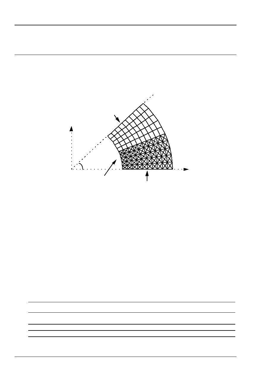
1.1 Geometry
Z
X
R
y
P
With
B
45°
C
D
E
F
Internal radius
= 0.1 m has
External radius
B = 0.2 m
Co-ordinates of the points:
WITH B C
D
E F
X 0.100 0.200
0.1 cos (22.5)
0.2 cos (22.5)
2 2
/
2
y 0.
0.
0.1 sin (22.5)
0.2 sin (22.5)
2 2
/
2
Z 0
0.
0.
0.
0.
0.
1.2
Material properties
E = 2 10
5
MPa
= 0.3
1.3
Boundary conditions and loadings
Internal pressure:
P = 60 MPa
Pressure interns variable (modeling P only):
P varies linearly from 60 MPa with t=1.s with 120 MPa with t=2.s
Code_Aster
®
Version
6.4
Titrate:
SSLV04 - Hollow roll in plane stresses
Date:
17/06/03
Author (S):
X. DESROCHES, P. HERMANN
Key
:
V3.04.004-E
Page:
3/36
Manual of Validation
V3.04 booklet: Linear statics of the voluminal structures
HT-66/03/008/A
2
Reference solution
2.1
Method of calculation used for the reference solution
In stress planes (cylinder on free board at the ends)
(
) (
)
zz
rr
R
R
has
B
has
R
has
B
has
R
U
E
has
B
has
R
R
=
=
-
-
=
-
+
=
=
-
- + +
0
1
1
0
1
1
2
2
2
2
2
2
2
2
2
2
2
2
2
2
2
P
B
P
B
P
B
One obtains:
for
0.1
59. 10
for
0.2
40. 10
60.
0.
100.
40.
0.
0.
6
6
R
U
R
U
R
R
rr
rr
zz
R
zz
R
=
=
=
=
=
=
=
=
=
=
=
=
-
-
-
Passage in the system of Cartesian axes:
(
)
xx
rr
R
yy
rr
R
xy
rr
R
=
+
-
=
+
+
=
-
-
-
cos
sin
sin cos
sin
cos
sin cos
sin cos
sin cos
cos
sin
2
2
2
2
2
2
2
2
2
with:
·
= 0° at points A and B,
·
= 22.5° at the points C and D,
·
= 45° at the points E and F.
2.2
Results of reference
Displacements (U, v) and forced
(
)
xx
yy
zz
xy
,
at the points A, B, C, D, E, F.
2.3 References
bibliographical
[1]
Guide VPCS. SSLV04/89
[2]
Y.C. FUNG. Foundations off solid mechanics. Prentice-hall, Inc. Englewood Cliffs. NJ. 1965
p. 243 to 245.
[3]
J. COURBON. Resistance of the materials p 649

Code_Aster
®
Version
6.4
Titrate:
SSLV04 - Hollow roll in plane stresses
Date:
17/06/03
Author (S):
X. DESROCHES, P. HERMANN
Key
:
V3.04.004-E
Page:
4/36
Manual of Validation
V3.04 booklet: Linear statics of the voluminal structures
HT-66/03/008/A
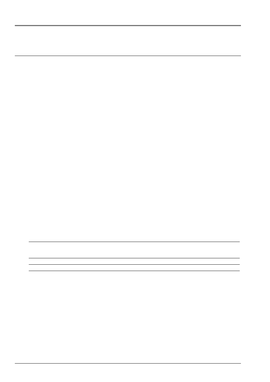
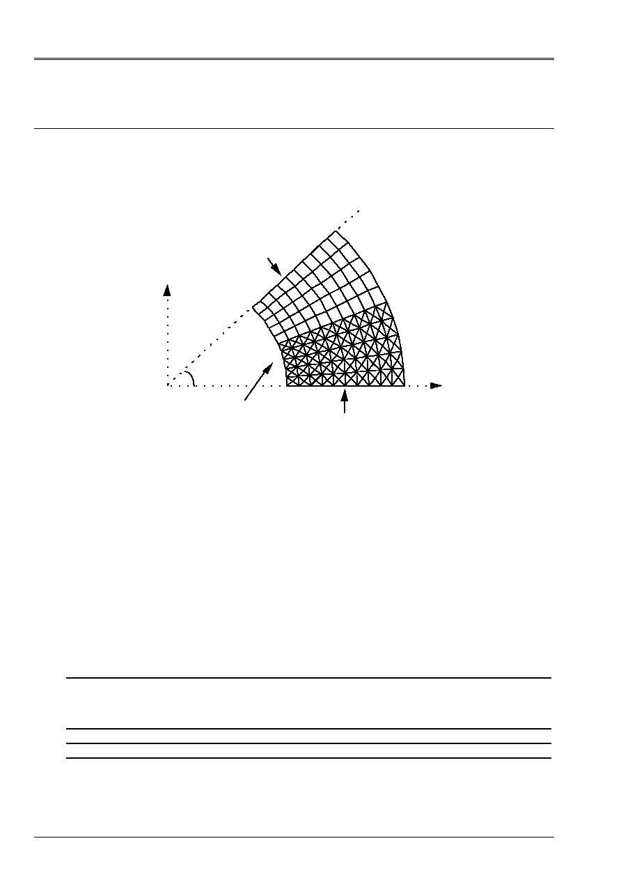
3 Modeling
With
3.1
Characteristics of modeling
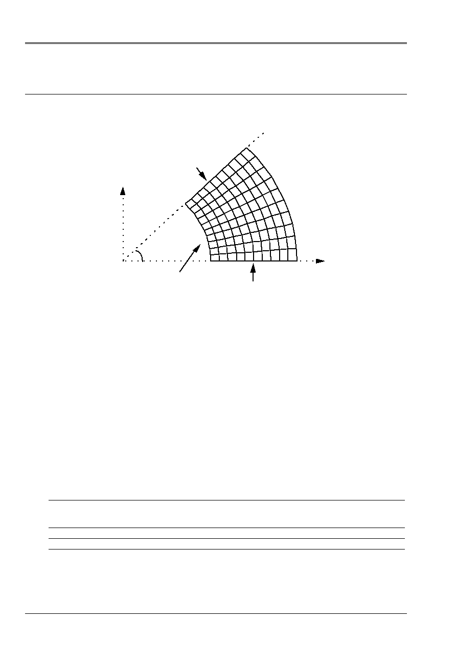
Elements 3D (PENTA6 and HEXA8)
Mesh obtained by extrusion starting from a mesh 2D resembling the mesh below (30
elements in the radial direction with déraffinement progressive and 15+15 elements in the direction
circumferential).
With
B
E
F
y
X
45°
Normally locked face
Face locked out of Dy
Face with imposed pressure
Along axis Z:
1 layer of elements
Total thickness:
0.01
Limiting conditions:
node F: U
Z
= 0
face AB locked out of Dy
normally locked face EFF
pressure on face AE p = 60.
Names of the nodes:
With = N993
B=N1443
C=N1
D=N31
E=N496
F=N495
3.2
Characteristics of the mesh
A number of nodes: 1922
A number of meshs and types: 900 PENTA6, 450 HEXA8 and 90 QUAD4 (faces internal skin).
3.3 Functionalities
tested
Controls
AFFE_CHAR_MECA DDL_IMPO
FACE_IMPO
PRES_REP
GROUP_NO
GROUP_MA
GROUP_MA
DNOR
“MECHANICAL” AFFE_MODELE “3D”
ALL
DEFI_MATERIAU ELAS
CALC_NO “EPSI_NOEU_DEPL”
“SIGM_NOEU_DEPL”
POST_RELEVE “EXTRACTION”
MODI_REPERE DEFI_REPERE “USER”
“CYLINDRICAL”

Code_Aster
®
Version
6.4
Titrate:
SSLV04 - Hollow roll in plane stresses
Date:
17/06/03
Author (S):
X. DESROCHES, P. HERMANN
Key
:
V3.04.004-E
Page:
5/36
Manual of Validation
V3.04 booklet: Linear statics of the voluminal structures
HT-66/03/008/A
4
Results of modeling A
4.1 Values
tested
Localization Size
Reference
Aster %
difference
With U
5.9
10
5
5.8950
10
5
0.08
v
0.
eps
-
xx
60.
59.2225
1.30
yy
100. 100.4159 0.42
zz
0. 0.3093
-
xy
0.
1.0442 -
xx
4.5 10
4
4.472 10
4
0.62
yy
5.9 10
4
5.904
10
4
0.08
xy
0.
6.788 10
5
-
B U
4
10
5
3.9959
10
5
0.10
v
0.
eps
-
xx
0.
1.7246
-
yy
40. 39.2451
1.89
zz
0.
0.3761 -
xy
0.
0.2659 -
xx
0.6 10
4
6.692 10
5
11.54
yy
2. 10
4
1.994
10
4
0.31
xy
0.
1.728 10
6
-
E U
4.17193
10
5
4.1708
10
5
0.03
v
4.17193 10
5
4.1708
10
5
0.03
xx
20.
19.0824
4.59
yy
20. 21.1394
5.70
zz
0. 0.0870
-
xy
80.
79.8831 0.15
xx
0.7 10
4
0.636
10
4
9.18
yy
0.7 10
4
0.769
10
4
9.92
xy
5.2 10
4
5.192 10
4
0.15
F U
2.82843
10
5
2.8302
10
5
0.06
v
2.82843 10
5
2.8302
10
5
0.06
xx
20.
18.9528
5.24
yy
20. 19.9104
0.45
zz
0. 0.1198
-
xy
20. 20.1809 0.90
xx
0.7 10
4
0.647
10
4
7.54
yy
0.7 10
4
0.709
10
4
1.35
xy
1.3 10
4
1.312
10
4
0.90
Code_Aster
®
Version
6.4
Titrate:
SSLV04 - Hollow roll in plane stresses
Date:
17/06/03
Author (S):
X. DESROCHES, P. HERMANN
Key
:
V3.04.004-E
Page:
6/36
Manual of Validation
V3.04 booklet: Linear statics of the voluminal structures
HT-66/03/008/A
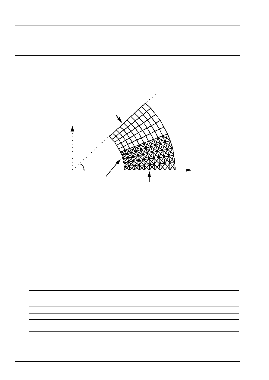
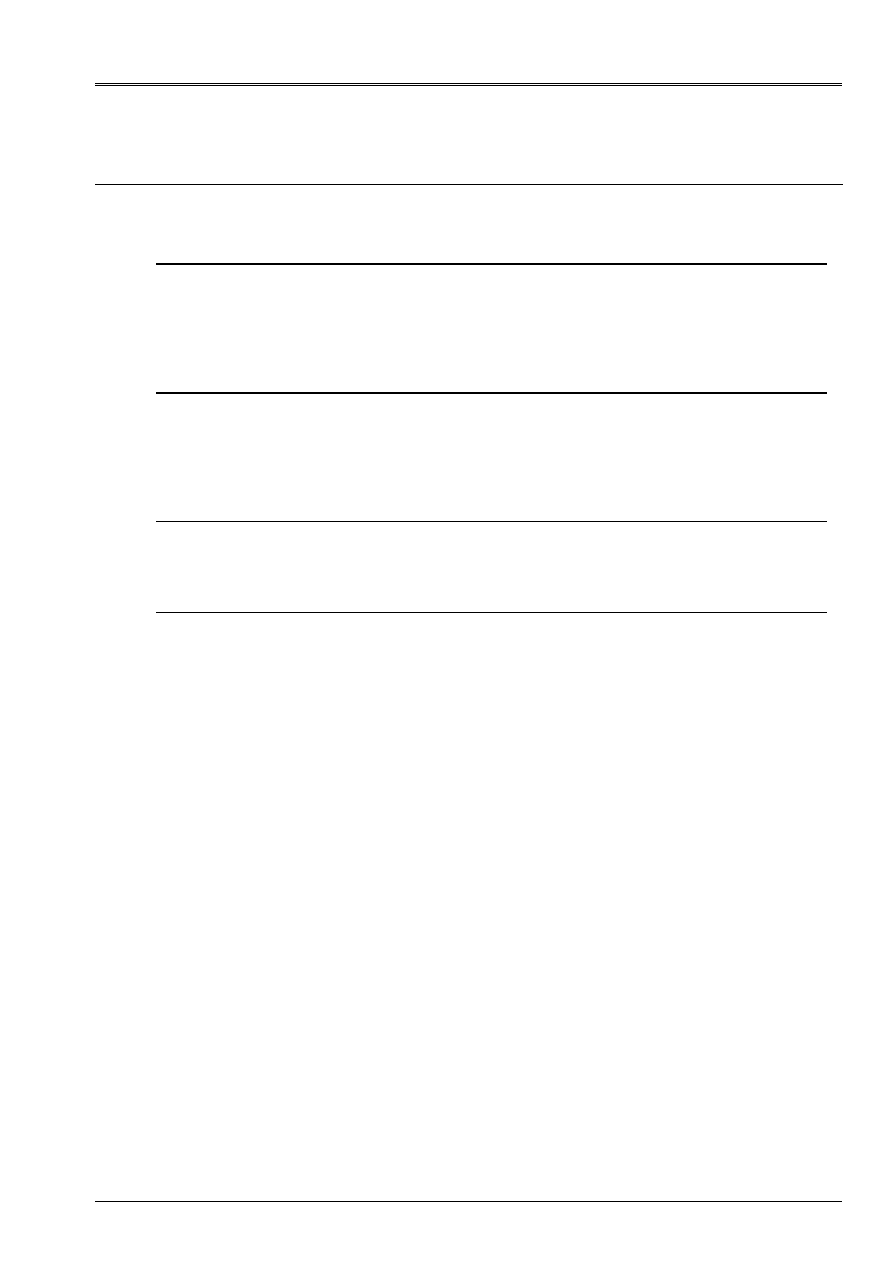
5 Modeling
B
5.1
Characteristics of modeling
Elements 3D (PENTA15 and HEXA20)
Mesh obtained by extrusion starting from the mesh 2D below (modeling F)
X
y
With
B
F
E
45°
Face with imposed pressure
Face locked in dx
Normally locked face
Along axis Z:
2 layers of elements
Total thickness:
0.01
Limiting conditions:
node F = U
Z
= 0
face AB locked in dx
normally locked face EFF
pressure on face AE
p = 60.
Names of the nodes:
With = NO2
B = NO361
C = NO121
D = NO584
E = NO155
F = NO503
5.2
Characteristics of the mesh
A number of nodes: 2115
A number of meshs and types: 400 PENTA15, 100 HEXA20 40 QUAD8 (faces skin interns)
5.3 Functionalities
tested
Controls
AFFE_CHAR_MECA DDL_IMPO
FACE_IMPO
PRES_REP
GROUP_NO
GROUP_MA
GROUP_MA
DNOR
“MECHANICAL” AFFE_MODELE “3D”
ALL
DEFI_MATERIAU ELAS
CALC_CHAM_ELEM “SIGM_ELNO_DEPL”
“EPSI_ELNO_DEPL”
POST_RELEVE “EXTRACTION”

Code_Aster
®
Version
6.4
Titrate:
SSLV04 - Hollow roll in plane stresses
Date:
17/06/03
Author (S):
X. DESROCHES, P. HERMANN
Key
:
V3.04.004-E
Page:
7/36
Manual of Validation
V3.04 booklet: Linear statics of the voluminal structures
HT-66/03/008/A
6
Results of modeling B
6.1 Values
tested
Localization Size
Reference
Aster %
difference
With U
0. eps
-
v
5.9 10
5
5.8944
10
5
0.09
xx
100.
99.6056
0.39
yy
60.
59.4473
0.92
zz
0. 0.0196
-
xy
0. 0.2481
-
xx
5.9 10
4
5.87
10
4
0.48
yy
4.5 10
4
4.47 10
4
0.74
xy
0. 1.61
10
6
-
B U
0. eps
-
v
4 10
5
3.9974
10
5
0.07
xx
40.
39.9711
0.07
yy
0. 0.0781
-
zz
0. 5.7992
10
3
-
xy
0.
0.0182
-
xx
2. 10
4
1.997
10
4
0.13
yy
0.6. 10
4
0.596 10
4
0.67
xy
0.
1.1810
7
-
E U
4.17193
10
5
4.1680
10
5
0.09
v
4.17193 10
5
4.1680
10
5
0.09
xx
20.
20.0515
0.26
yy
20. 20.0264
0.13
zz
0. 0.0155
-
xy
80. 79.7918
0.26
xx
0.7 10
4
0.702
10
4
0.34
yy
0.7 10
4
0.701
10
4
0.11
xy
5.2 10
4
5.19
10
4
0.26
F U
2.82843
10
5
2.82656 10
5
0,07
v
2.82843 10
5
2.82656
10
5
0.07
xx
20.
20.0099
0.05
yy
20. 19.9980
0.01
zz
0.
3.90 10
4
-
xy
20. 20.0122
0.06
xx
0.7 10
4
0.7005
10
4
0.08
yy
0.7 10
4
0.6997
10
4
0.03
xy
1.3 10
4
1.3008
10
4
0.06
Code_Aster
®
Version
6.4
Titrate:
SSLV04 - Hollow roll in plane stresses
Date:
17/06/03
Author (S):
X. DESROCHES, P. HERMANN
Key
:
V3.04.004-E
Page:
8/36
Manual of Validation
V3.04 booklet: Linear statics of the voluminal structures
HT-66/03/008/A
7 Modeling
C
7.1
Characteristics of modeling
Elements 3D (TETRA4)
AB is on axis OX
Cutting:
21 equidistant nodes on segments AB, CD and EFF
21 equidistant nodes on arcs ACE and BDF
Along axis Z:
1 layer of elements
Total thickness:
0.01
Limiting conditions:
node F: U
Z
= 0
face AB locked out of Dy
normally locked face EFF
pressure on face AE
p = 60.
Names of the nodes:
With = N165
B = N4
C = N209
D = N82
E = N244
F = N1068
7.2
Characteristics of the mesh
A number of nodes: 1115
A number of meshs and types: 3724 TETRA4 and 1760 TRIA3 (faces skin interns)
7.3 Functionalities
tested
Controls
AFFE_CHAR_MECA DDL_IMPO
FACE_IMPO
PRES_REP
GROUP_NO
GROUP_MA
GROUP_MA
DNOR
“MECHANICAL” AFFE_MODELE “3D”
ALL
DEFI_MATERIAU ELAS
CALC_NO “EPSI_NOEU_DEPL”
“SIGM_NOEU_DEPL”

Code_Aster
®
Version
6.4
Titrate:
SSLV04 - Hollow roll in plane stresses
Date:
17/06/03
Author (S):
X. DESROCHES, P. HERMANN
Key
:
V3.04.004-E
Page:
9/36
Manual of Validation
V3.04 booklet: Linear statics of the voluminal structures
HT-66/03/008/A
8
Results of modeling C
8.1 Values
tested
Localization Size Reference
Aster %
difference
With U
5.9
10
5
5.8901
10
5
0.17
v
0. eps
-
xx
60.
57.2290
4.62
yy
100. 97.8711
2.13
zz
0. 0.0568
-
xy
0.
2.6589 -
xx
4.5 10
4
4.33 10
4
3.77
yy
5.9 10
4
5.75
10
4
2.52
xy
0.
1.73 10
5
-
B U
4
10
5
3.9878
10
5
0.30
v
0. eps
-
xx
0.
1.5296
-
yy
40. 40.9839
2.46
zz
0.
0.1006 -
xy
0.
0.8513 -
xx
0.6 10
4
6.897 10
4
14.95
yy
2. 10
4
2.074
10
4
3.68
xy
0.
5.534 10
5
-
E U
4.17193
10
5
4.1655
10
5
0.15
v
4.17193 10
5
4.1655
10
5
0.15
xx
20.
17.9096
10.45
yy
20. 21.8929
9.46
zz
0.
0.3679 -
xy
80.
77.6897
2.89
xx
0.7 10
4
0.573
10
4
18.20
yy
0.7 10
4
0.832
10
4
18.79
xy
5.2 10
4
5.050
2.89
F U
2.82843
10
5
2.8251
10
5
0.12
v
2.82843 10
5
2.8251
10
5
0.12
xx
20.
18.4444
7.78
yy
20. 19.8876
0.56
zz
0.
0.3910 -
xy
20.
20.1631
0.81
xx
0.7 10
4
0.630
10
4
10.05
yy
0.7 10
4
0.723
10
4
3.35
xy
1.3 10
4
1.311
10
4
0.81

Code_Aster
®
Version
6.4
Titrate:
SSLV04 - Hollow roll in plane stresses
Date:
17/06/03
Author (S):
X. DESROCHES, P. HERMANN
Key
:
V3.04.004-E
Page:
10/36
Manual of Validation
V3.04 booklet: Linear statics of the voluminal structures
HT-66/03/008/A
9 Modeling
D
9.1
Characteristics of modeling
Element 3D (TETRA10)
AB is on axis OX
Cutting:
11 equidistant nodes on segments AB, CD and EFF
11 equidistant nodes on arcs ACE and BDF
Along axis Z:
1 layer of elements
Total thickness:
0.01
Limiting conditions:
node F: U
Z
= 0
face AB locked out of Dy
normally locked face EFF
pressure on face AE
p = 60.
Names of the nodes:
With = N184
B = N4
C = N207
D = N50
E = N22
F = N726
9.2
Characteristics of the mesh
A number of nodes: 1395
A number of meshs and types: 652 TETRA10 and 480 TRIA6 (faces skin interns)
9.3 Functionalities
tested
Controls
AFFE_CHAR_MECA DDL_IMPO
FACE_IMPO
PRES_REP
GROUP_NO
GROUP_MA
GROUP_MA
DNOR
“MECHANICAL” AFFE_MODELE “3D”
ALL
DEFI_MATERIAU ELAS
CALC_NO “EPSI_NOEU_DEPL”
“SIGM_NOEU_DEPL”

Code_Aster
®
Version
6.4
Titrate:
SSLV04 - Hollow roll in plane stresses
Date:
17/06/03
Author (S):
X. DESROCHES, P. HERMANN
Key
:
V3.04.004-E
Page:
11/36
Manual of Validation
V3.04 booklet: Linear statics of the voluminal structures
HT-66/03/008/A
10 Results of modeling D
10.1 Values
tested
Localization Size Reference
Aster %
difference
With U
5.9
10
5
5.8974
10
5
0.04
v
0. eps
-
xx
60.
60.3816
0.64
yy
100. 99.1907
0.81
zz
0.
0.9707
-
xy
0.
0.2979
-
xx
4.5 10
4
4.49 10
4
0.17
yy
5.9 10
4
5.88
10
4
0.34
xy
0.
1.94 10
6
-
B U
4
10
5
3.9989
10
5
0.03
v
0. eps
-
xx
0.
0.0388
-
yy
40. 40.0725
0.18
zz
0.
0.0046
-
xy
0. 0.1634
-
xx
0.6 10
4
0.599 10
4
0.15
yy
2. 10
4
2.003
10
4
0.16
xy
0. 1.062
10
6
-
E U
4.17193
10
5
4.17021
10
5
0.04
v
4.17193 10
5
4.17021
10
5
0.04
xx
20.
19.1178
4.41
yy
20. 19.6399
1.80
zz
0.
1.0206
-
xy
80.
79.7804
0.27
xx
0.7 10
4
0.677
10
4
3.34
yy
0.7 10
4
0.711
10
4
1.50
xy
5.2 10
4
5.186 10
4
0.27
F U
2.82843
10
5
2.82718
10
5
0.04
v
2.82843 10
5
2.82718
10
5
0.04
xx
20.
20.1903
0.95
yy
20. 19.9023
0.49
zz
0.
0.0016
-
xy
20.
20.0570
0.28
xx
0.7 10
4
0.711
10
4
1.57
yy
0.7 10
4
0.692
10
4
1.10
xy
1.3 10
4
1.304 10
4
0.28
Code_Aster
®
Version
6.4
Titrate:
SSLV04 - Hollow roll in plane stresses
Date:
17/06/03
Author (S):
X. DESROCHES, P. HERMANN
Key
:
V3.04.004-E
Page:
12/36
Manual of Validation
V3.04 booklet: Linear statics of the voluminal structures
HT-66/03/008/A
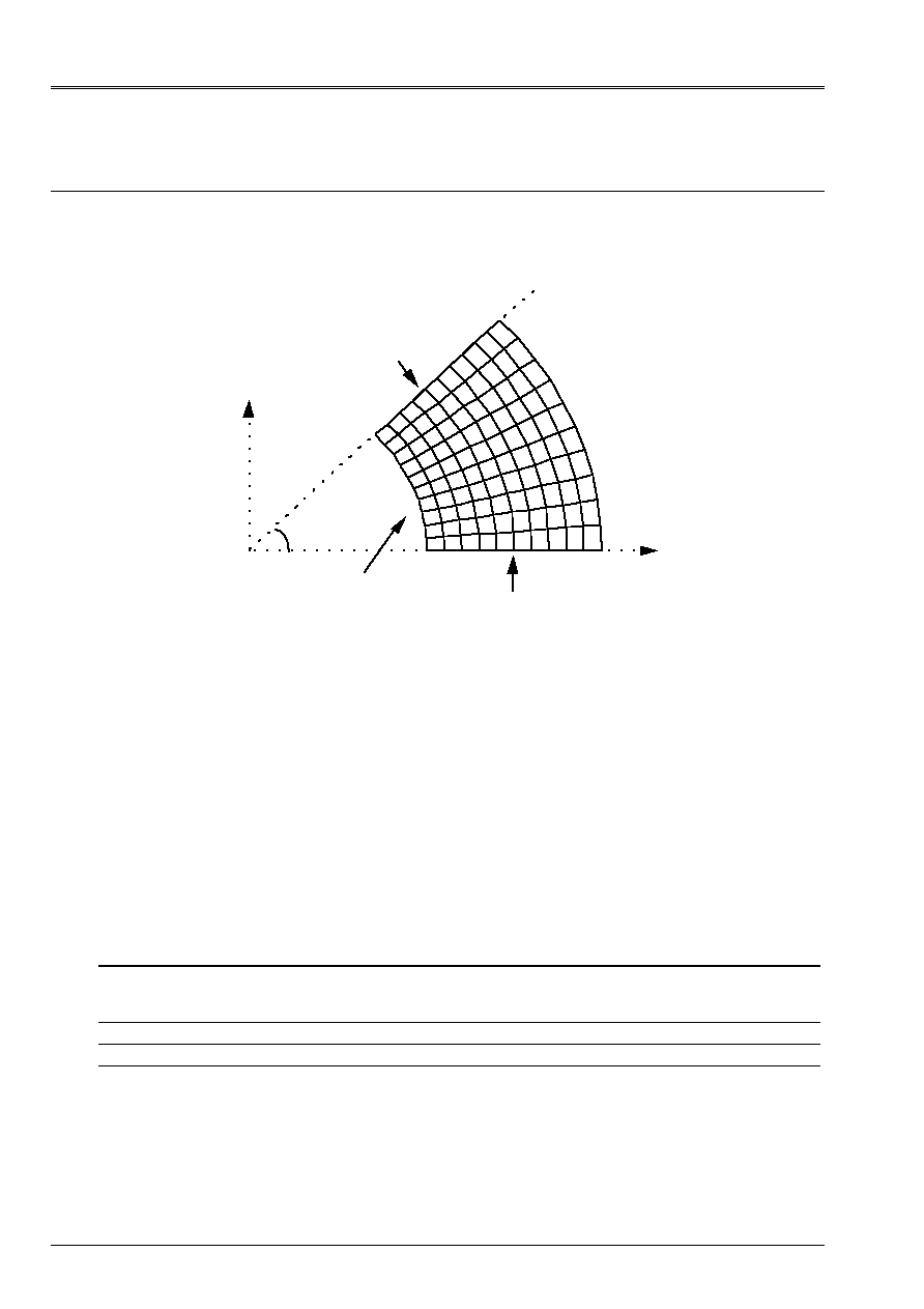
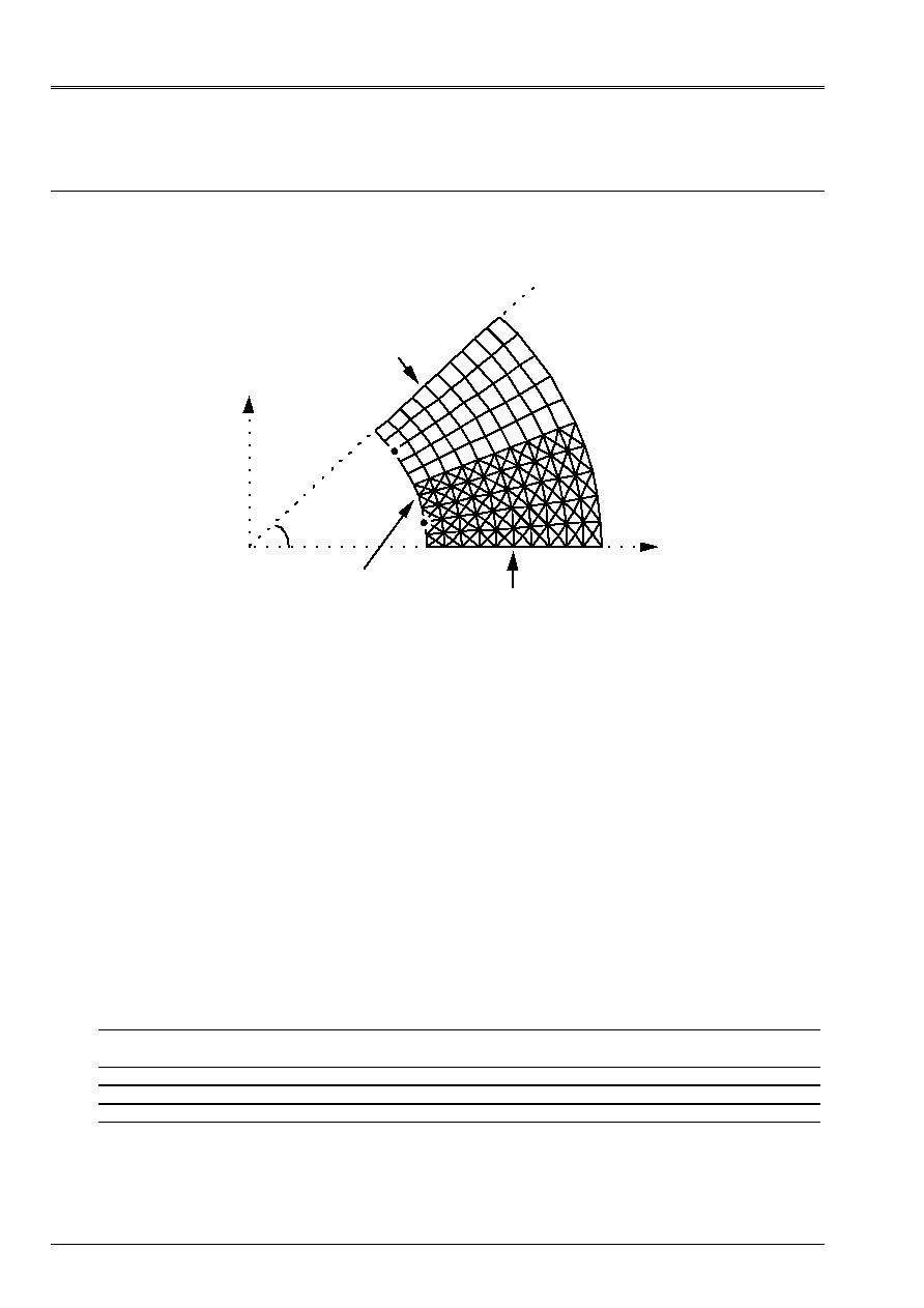
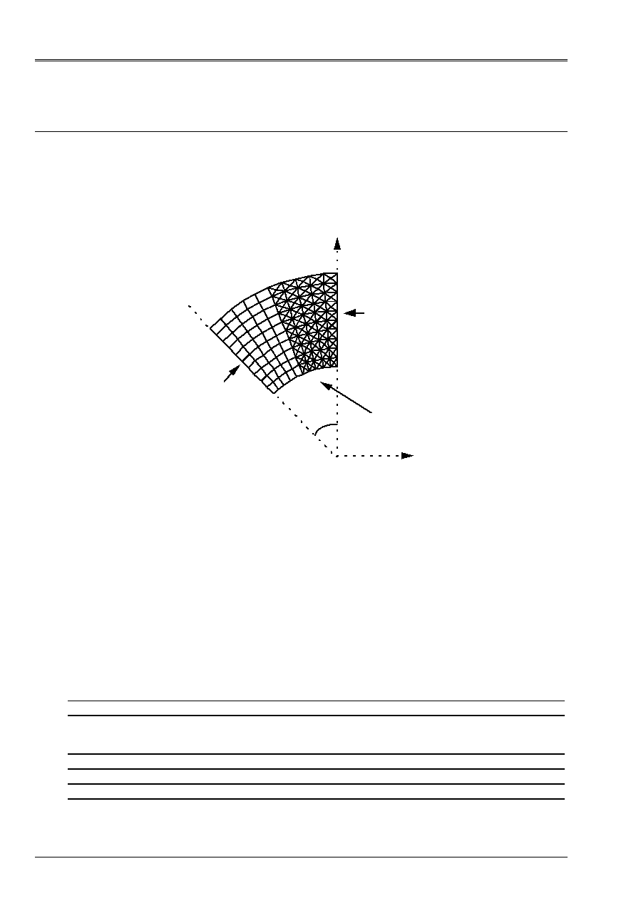
11 Modeling
E
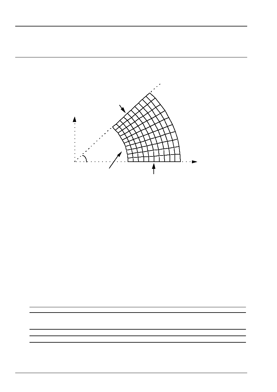
11.1 Characteristics of modeling
C_plan elements (TRIA3 + QUAD4)
Mesh 2D resembling the mesh below (30 elements in the radial direction with
déraffinement progressive and 15+15 elements in the circumferential direction).
With
B
E
F
y
X
45°
Normally locked face
Face locked out of Dy
Face with imposed pressure
C
D
Limiting conditions:
side AB locked out of Dy
normally locked side EFF
pressure on AE p = 60.
Names of the nodes:
With = N1
B = N451
C = N496
D = N495
E = N990
F = N989
11.2 Characteristics of the mesh
A number of nodes: 961
A number of meshs and types: 900 TRIA3, 450 QUAD4
11.3 Functionalities
tested
Controls
AFFE_CHAR_MECA DDL_IMPO
FACE_IMPO
PRES_REP
GROUP_NO
GROUP_MA
GROUP_MA
DNOR
“MECHANICAL” AFFE_MODELE “C_PLAN” ALL
DEFI_MATERIAU ELAS
CALC_NO “EPSI_NOEU_DEPL”
“SIGM_NOEU_DEPL”
“CYLINDRICAL” MODI_REPERE DEFI_REPERE

Code_Aster
®
Version
6.4
Titrate:
SSLV04 - Hollow roll in plane stresses
Date:
17/06/03
Author (S):
X. DESROCHES, P. HERMANN
Key
:
V3.04.004-E
Page:
13/36
Manual of Validation
V3.04 booklet: Linear statics of the voluminal structures
HT-66/03/008/A
12 Results of modeling E
12.1 Values
tested
Localization Size Reference
Aster %
difference
With U
5.9
10
5
5.8957
10
5
0.07
v
0. eps
-
xx
60.
59.3645
1.06
yy
100. 100.2653 0.26
zz
0. 0. -
xy
0.
1.0472 -
xx
4.5 10
4
4.472 10
4
0.62
yy
5.9 10
4
5.904
10
4
0.06
xy
0.
6.807 10
6
-
B U
4.
10
5
3.9965
10
5
0.09
v
0. eps
-
xx
0.
1.4986
-
yy
40. 39.4415
1.40
zz
0. 0. -
xy
0.
0.2658 -
xx
0.6 10
4
0.667 10
5
11.09
yy
2. 10
4
1.995
10
4
0.27
xy
0.
1.728 10
6
-
E U
4.17193
10
5
4.17101
10
5
0.02
v
4.17193 10
5
4.17101
10
5
0.02
xx
20.
19.0706
4.65
yy
20. 21.1354
5.68
zz
0. 0. -
xy
80.
79.8720
0.16
xx
0.7 10
4
0.636
10
4
9.07
yy
0.7 10
4
0.771
10
4
10.10
xy
5.2 10
4
5.192 10
4
0.16
F U
2.82843
10
5
2.82996
10
5
0.05
v
2.82843 10
5
2.82996
10
5
0.05
xx
20.
18.9626
5.19
yy
20. 19.8483
0.76
zz
0. 0. -
xy
20.
20.2466
1.23
xx
0.7 10
4
0.650
10
4
7.08
yy
0.7 10
4
0.708
10
4
1.14
xy
1.3 10
4
1.316 10
4
1.23
Code_Aster
®
Version
6.4
Titrate:
SSLV04 - Hollow roll in plane stresses
Date:
17/06/03
Author (S):
X. DESROCHES, P. HERMANN
Key
:
V3.04.004-E
Page:
14/36
Manual of Validation
V3.04 booklet: Linear statics of the voluminal structures
HT-66/03/008/A
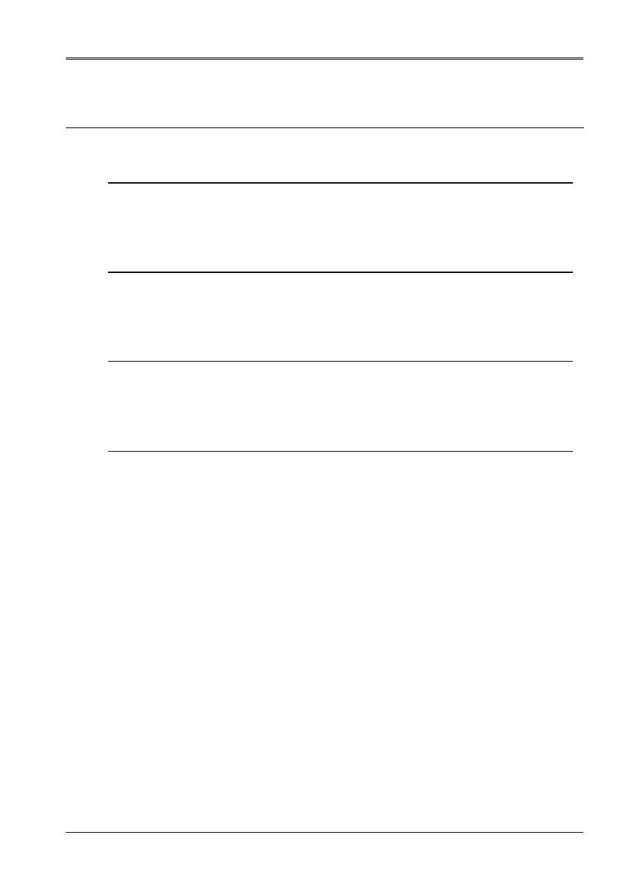
13 Modeling
F
13.1 Characteristics of modeling
C_plan elements (QUAD8 + TRIA6)
X
y
With
B
F
E
45°
Face with imposed pressure
Face locked in dx
Normally locked face
C
D
Limiting conditions:
side AB locked in dx
normally locked side EFF
pressure on AE p = 60.
Names of the nodes:
With = N2
B = N361
C = N121
D = N584
E = N155
F = N503
13.2 Characteristics of the mesh
A number of nodes: 591
A number of meshs and types: 200 TRIA6, 50 QUAD8
13.3 Functionalities
tested
Controls
AFFE_CHAR_MECA DDL_IMPO
FACE_IMPO
PRES_REP
GROUP_NO
GROUP_MA
GROUP_MA
DNOR
“MECHANICAL” AFFE_MODELE “C_PLAN”
ALL
DEFI_MATERIAU ELAS
CALC_CHAM_ELEM “SIGM_ELNO_DEPL”
POST_RELEVE “EXTRACTION”

Code_Aster
®
Version
6.4
Titrate:
SSLV04 - Hollow roll in plane stresses
Date:
17/06/03
Author (S):
X. DESROCHES, P. HERMANN
Key
:
V3.04.004-E
Page:
15/36
Manual of Validation
V3.04 booklet: Linear statics of the voluminal structures
HT-66/03/008/A
14 Results of modeling F
14.1 Values
tested
Localization Size Reference
Aster %
difference
With U
0.
0.
-
v
5.9
10
5
5.8945
10
5
0.09
xx
100.
99.6095
0.39
yy
60.
59.4620
0.90
zz
0. 0. -
xy
0. 0.2441
-
xx
5.9 10
4
5.872
10
4
0.47
yy
4.5 10
4
4.467 10
4
0.73
xy
0. 1.586
10
6
-
B U
0. eps
-
v
4
10
5
3.9974
10
5
0.07
xx
40.
39.9774
0.06
yy
0. 0.0786
-
zz
0. 0. -
xy
0.
0.0181
-
xx
2. 10
4
1.998
10
4
0.11
yy
0.6 10
4
0.596 10
4
0.67
xy
0.
1.176 10
7
-
E U
4.17193
10
5
4.16814 10
5
0.09
v
4.17193 10
5
4.16814
10
5
0.09
xx
20.
20.0024
0.01
yy
20. 20.0045
0.02
zz
0. 0. -
xy
80. 79.8164
0.23
xx
0.7 10
4
0.7001
10
4
0.01
yy
0.7 10
4
0.7002
10
4
0.03
xy
5.2 10
4
5.188
10
4
0.23
F
U
2.82843 10
5
2.82655 10
5
0.07
v
2.82843 10
5
2.82655
10
5
0.07
xx
20.
20.0083
0.04
yy
20. 19.9915
0.04
zz
0. 0. -
xy
20. 20.0138
0.07
xx
0.7 10
4
0.7005
10
4
0.08
yy
0.7 10
4
0.6995
10
4
0.08
xy
1.3 10
4
1.3009
10
4
0.07
Code_Aster
®
Version
6.4
Titrate:
SSLV04 - Hollow roll in plane stresses
Date:
17/06/03
Author (S):
X. DESROCHES, P. HERMANN
Key
:
V3.04.004-E
Page:
16/36
Manual of Validation
V3.04 booklet: Linear statics of the voluminal structures
HT-66/03/008/A
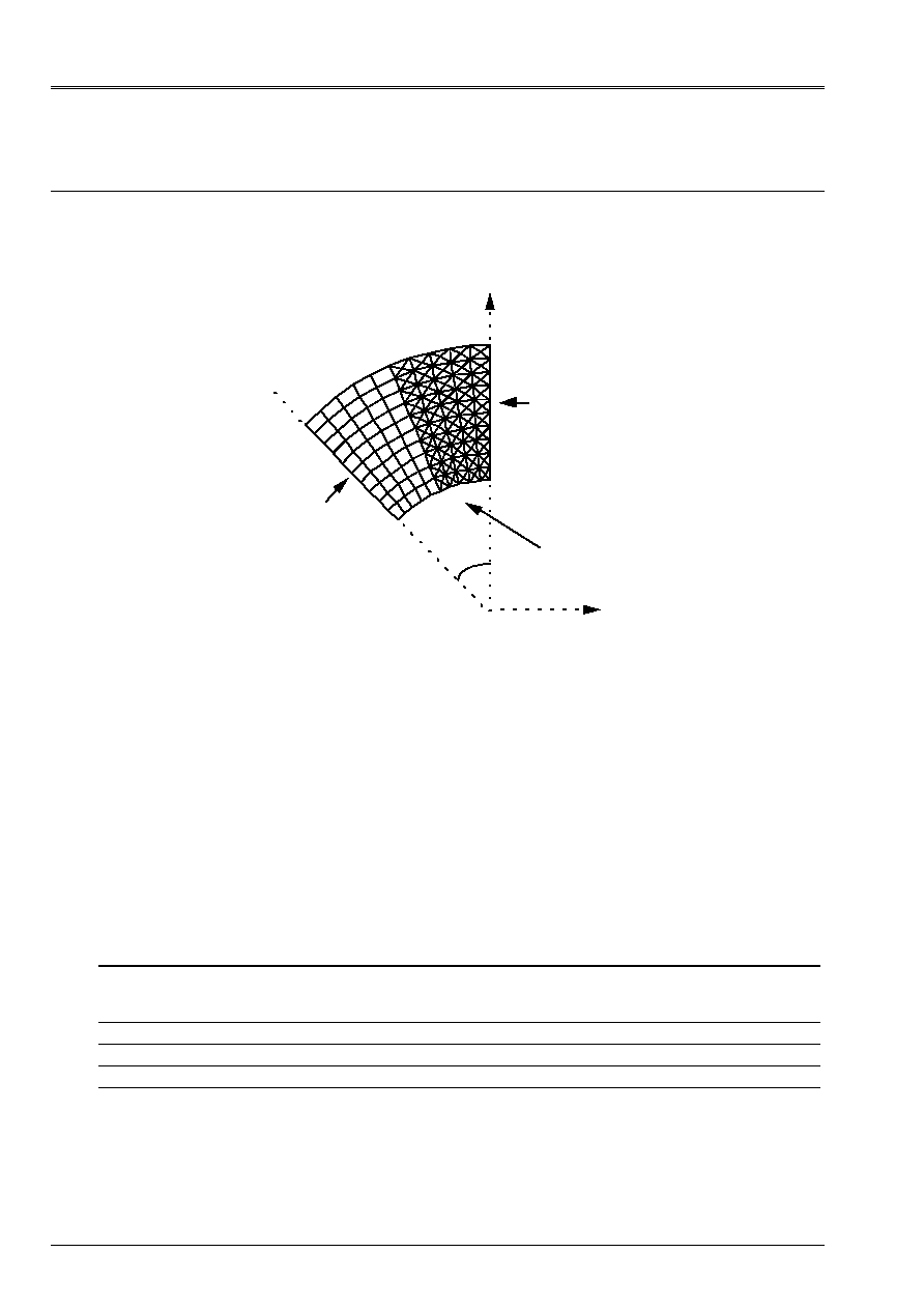
15 Modeling
G
15.1 Characteristics of modeling
C_plan (QUAD9)
With
B
E
F
y
X
45°
Normally locked face
Face locked out of Dy
Face with imposed pressure
C
D
Limiting conditions:
side AB locked out of Dy
normally locked side EFF
pressure on AE p = 60.
Names of the nodes:
With = N1
B = N347
C = N21
D = N432
E = N39
F = N229
15.2 Characteristics of the mesh
A number of nodes: 441
A number of meshs and types: 100 QUAD9
15.3 Functionalities
tested
Controls
AFFE_CHAR_MECA DDL_IMPO
FACE_IMPO
PRES_REP
GROUP_NO
GROUP_MA
GROUP_MA
DNOR
“MECHANICAL” AFFE_MODELE “C_PLAN”
ALL
DEFI_MATERIAU ELAS
CALC_CHAM_ELEM “SIGM_ELNO_DEPL”

Code_Aster
®
Version
6.4
Titrate:
SSLV04 - Hollow roll in plane stresses
Date:
17/06/03
Author (S):
X. DESROCHES, P. HERMANN
Key
:
V3.04.004-E
Page:
17/36
Manual of Validation
V3.04 booklet: Linear statics of the voluminal structures
HT-66/03/008/A
16 Results of modeling G
16.1 Values
tested
Localization Size Reference
Aster %
difference
With U
5.9
10
5
5.9000
10
5
0.00
v
0. eps
-
xx
60.
59.8354
0.27
yy
100. 99.8409
0.16
zz
0. 0. -
xy
0. 0.0283
-
xx
4.5 10
4
4.489 10
4
- 0.24
yy
5.9 10
4
5.890
10
4
0.18
xy
0.
1.839 10
7
-
B U
4
10
5
3.9999
10
5
0.001
v
0. eps
-
xx
0.
- 0.0189
-
yy
40. 40.0182
0.05
zz
0. 0. -
xy
0.
3.6815 10
3
-
xx
0.6 10
4
0.601 10
4
0.20
yy
2. 10
4
2.001
10
4
0.06
xy
0.
2.393 10
8
-
E U
4.17193
10
5
4.17195
10
5
0.00
v
4.17193 10
5
4.17195
10
5
0.00
xx
20.
19.9745
0.13
yy
20. 20.0311
0.16
zz
0. 0. -
xy
80.
79.8382
0.20
xx
0.7 10
4
0.698
10
4
0.25
yy
0.7 10
4
0.702
10
4
0.28
xy
5.2 10
4
5.189 10
4
0.20
F U
2.82843
10
5
2.82839
10
5
0.001
v
2.82843 10
5
2.82839
10
5
0.001
xx
20.
19.9960
0.02
yy
20. 20.0034
0.02
zz
0. 0. -
xy
20.
20.0185
0.09
xx
0.7 10
4
0.6997
10
4
0.04
yy
0.7 10
4
0.7002
10
4
0.03
xy
1.3 10
4
1.301 10
4
0.09
Code_Aster
®
Version
6.4
Titrate:
SSLV04 - Hollow roll in plane stresses
Date:
17/06/03
Author (S):
X. DESROCHES, P. HERMANN
Key
:
V3.04.004-E
Page:
18/36
Manual of Validation
V3.04 booklet: Linear statics of the voluminal structures
HT-66/03/008/A
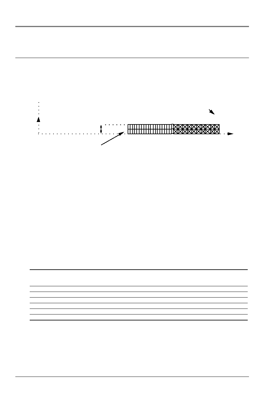
17 Modeling
H
17.1 Characteristics of modeling
Elements axis (TRIA3 + QUAD4)
y
X
Node locked out of Dy
Face with imposed pressure
With
B
C
E
F
D
Center cylinder
0.01m
Limiting conditions:
node F locked out of Dy
pressure on AE p = 60.
Names of the nodes:
With = N111
B = N1
C = N112
D = N3
E = N113
F = N4
17.2 Characteristics of the mesh
A number of nodes: 113
A number of meshs and types: 40 QUAD4, 80 TRIA3
17.3 Functionalities
tested
Controls
AFFE_CHAR_MECA DDL_IMPO
FACE_IMPO
PRES_REP
GROUP_NO
GROUP_MA
GROUP_MA
DNOR
“MECHANICAL” AFFE_MODELE “AXIS” ALL
DEFI_MATERIAU ELAS
CALC_CHAM_ELEM “SIGM_ELNO_DEPL”
CREA_RESU EVOL_ELAS DEPL
CALC_ELEM “SIGM_ELNO_DEPL”
INTE_MAIL_2D
POST_RCCM

Code_Aster
®
Version
6.4
Titrate:
SSLV04 - Hollow roll in plane stresses
Date:
17/06/03
Author (S):
X. DESROCHES, P. HERMANN
Key
:
V3.04.004-E
Page:
19/36
Manual of Validation
V3.04 booklet: Linear statics of the voluminal structures
HT-66/03/008/A
18 Results of modeling H
18.1 Values
tested
Localization Size Reference
Aster %
difference
With U
5.9
10
5
5.8992
10
5
0.01
v
0. -
-
xx
60.
56.6060
5.66
yy
0. 1.0383 -
zz
100. 101.2924
1.29
xy
0.
1.1635
-
xx
4.5 10
4
4.36 10
4
2.99
yy
0.
6.18 10
5
-
zz
5.9 10
4
5.898
10
4
0.03
xy
0.
1.06 10
6
-
B U
4
10
5
3.9997
10
5
0.01
v
0. -
-
xx
0.
0.8951
-
yy
0.
0.4106
-
zz
40. 39.6001
1.00
xy
0.
0.1281
-
xx
0.6 10
4
0.632 10
4
5.43
yy
0.
6.011 10
5
-
zz
2. 10
4
1.999
10
4
0.02
xy
0.
8.325 10
7
-
E U
5.9
10
5
5.8992
10
5
0.01
v
0. -
-
xx
60.
56.6060
5.66
yy
0. 1.0383 -
zz
100. 101.2924
1.29
xy
0. 1.1635 -
xx
4.5 10
4
4.365 10
4
2.99
yy
0.
6.184 10
5
-
zz
5.9 10
4
5.898
10
4
0.03
xy
0. 1.063
10
6
-
F U
4
10
5
3.9997
10
5
0.01
v
0. -
-
xx
0.
0.4221
-
yy
0.
0.2280
-
zz
40. 39.8015
0.50
xy
0.
0.0020
-
xx
0.6 10
4
0.615 10
4
2.45
yy
0.
6.021 10
5
-
zz
2. 10
4
1.9998
10
4
0.01
xy
0.
1.280 10
8
-
Code_Aster
®
Version
6.4
Titrate:
SSLV04 - Hollow roll in plane stresses
Date:
17/06/03
Author (S):
X. DESROCHES, P. HERMANN
Key
:
V3.04.004-E
Page:
20/36
Manual of Validation
V3.04 booklet: Linear statics of the voluminal structures
HT-66/03/008/A
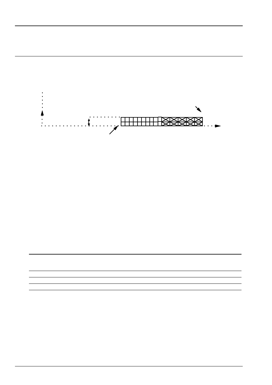
19 Modeling
I
19.1 Characteristics of modeling
Elements axis (TRIA6 + QUAD8)
y
Center cylinder
0.01m
X
With
B
C
E
D
F
Node locked out of Dy
Face with imposed pressure
Limiting conditions:
Node F locked out of Dy
pressure on AE p = 60.
Names of the nodes:
With = N8
B = N174
C = N5
D = N170
E = N3
F = N159
19.2 Characteristics of the mesh
A number of nodes: 175
A number of meshs and types: 20 QUAD8, 40 TRIA6
19.3 Functionalities
tested
Controls
AFFE_CHAR_MECA DDL_IMPO
FACE_IMPO
PRES_REP
GROUP_NO
GROUP_MA
GROUP_MA
DNOR
“MECHANICAL” AFFE_MODELE “AXIS” ALL
DEFI_MATERIAU ELAS
CALC_CHAM_ELEM “SIGM_ELNO_DEPL”
POST_RELEVE “EXTRACTION”

Code_Aster
®
Version
6.4
Titrate:
SSLV04 - Hollow roll in plane stresses
Date:
17/06/03
Author (S):
X. DESROCHES, P. HERMANN
Key
:
V3.04.004-E
Page:
21/36
Manual of Validation
V3.04 booklet: Linear statics of the voluminal structures
HT-66/03/008/A
20 Results of modeling I
20.1 Values
tested
Localization Size Reference
Aster %
difference
With U
5.9
10
5
5.9000
10
5
0.00
v
0. -
-
xx
60.
59.8976
0.17
yy
0.
0.0024
-
zz
100. 99.9089
0.09
xy
0.
0.0137
-
xx
4.5 10
4
4.493 10
4
0.14
yy
0.
6.003 10
5
-
zz
5.9 10
4
5.894
10
4
0.10
xy
0.
8.895 10
8
-
B U
4
10
5
4.0000
10
5
0.00
v
0. -
-
xx
0.
0.0308
-
yy
0.
0.0020
-
zz
40. 39.9738
0.07
xy
0. 0.0131 -
xx
0.6 10
4
0.598 10
4
0.33
yy
0.
6.002 10
5
-
zz
2. 10
4
1.998
10
4
0.09
xy
0. 8.495
10
8
-
E U
5.9
10
5
5.9000
10
5
0.00
v
0. -
-
xx
60.
59.8976
0.17
yy
0.
0.0024
-
zz
100. 99.9089
0.09
xy
0. 0.0137 -
xx
4.5 10
4
4.493 10
4
0.14
yy
0.
6.003 10
5
-
zz
5.9 10
4
5.894
10
4
0.10
xy
0. 8.895
10
8
-
F U
4
10
5
4.0000
10
5
0.00
v
0. -
-
xx
0.
0.0308
-
yy
0.
0.0020
-
zz
40. 39.9738
0.07
xy
0.
0.0131
-
xx
0.6 10
4
0.598 10
4
0.33
yy
0.
6.002 10
5
-
zz
2. 10
4
1.998
10
4
0.09
xy
0.
8.495 10
8
-
Code_Aster
®
Version
6.4
Titrate:
SSLV04 - Hollow roll in plane stresses
Date:
17/06/03
Author (S):
X. DESROCHES, P. HERMANN
Key
:
V3.04.004-E
Page:
22/36
Manual of Validation
V3.04 booklet: Linear statics of the voluminal structures
HT-66/03/008/A
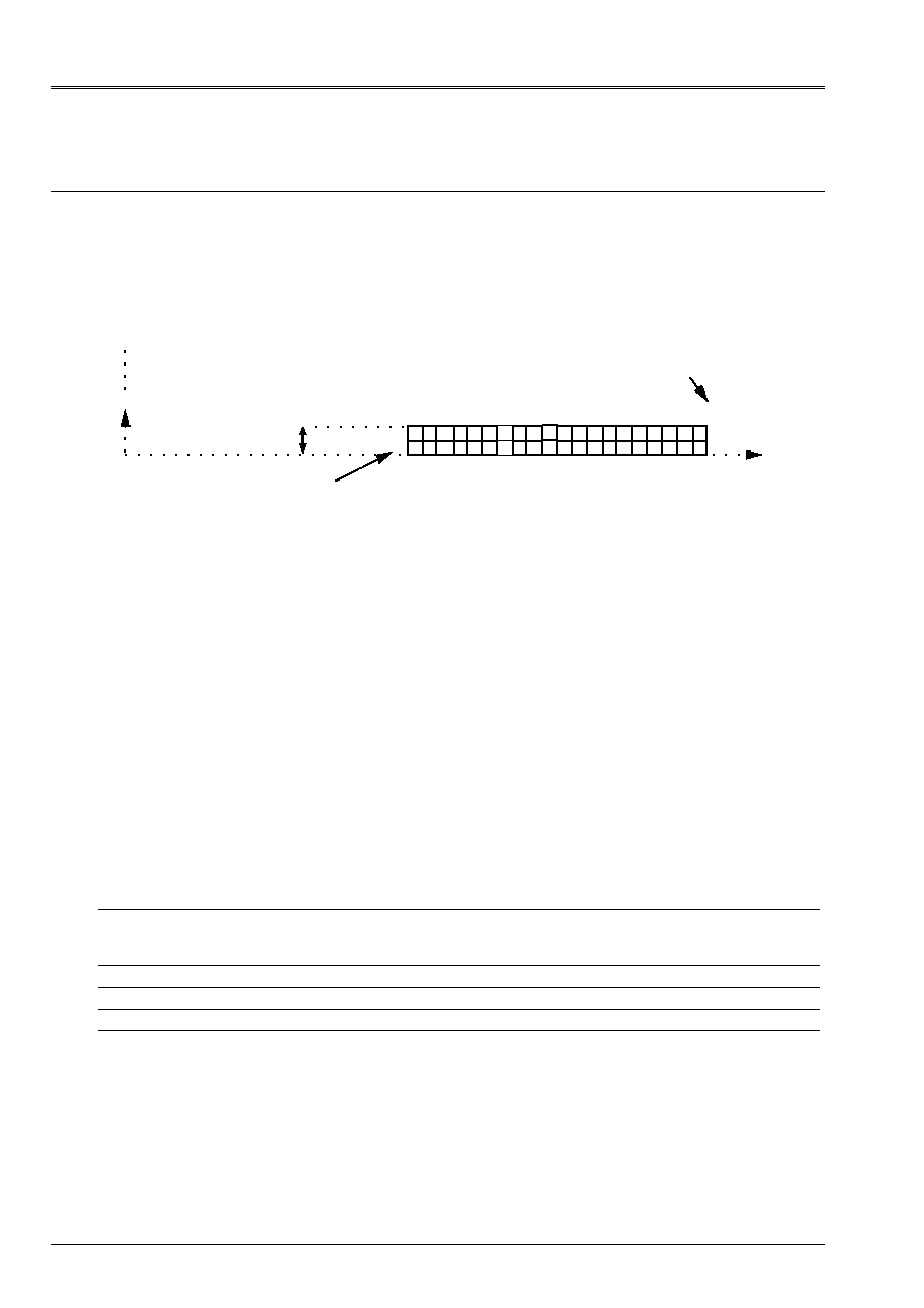
21 Modeling
J
21.1 Characteristics of modeling
Elements axis (QUAD9)
0.01m
y
X
With
B
C
E
D
F
Node locked out of Dy
Face with imposed pressure
Center cylinder
Limiting conditions:
node F locked out of Dy
pressure on AE p = 60.
Names of the nodes:
With = N196
B = N1
C = N200
D = N5
E = N202
F = N7
21.2 Characteristics of the mesh
A number of nodes: 205
A number of meshs and types: 40 QUAD9
21.3 Functionalities
tested
Controls
AFFE_CHAR_MECA DDL_IMPO
FACE_IMPO
PRES_REP
GROUP_NO
GROUP_MA
GROUP_MA
DNOR
“MECHANICAL” AFFE_MODELE “AXIS” ALL
DEFI_MATERIAU ELAS
CALC_CHAM_ELEM “SIGM_ELNO_DEPL”
POST_RELEVE “EXTRACTION”

Code_Aster
®
Version
6.4
Titrate:
SSLV04 - Hollow roll in plane stresses
Date:
17/06/03
Author (S):
X. DESROCHES, P. HERMANN
Key
:
V3.04.004-E
Page:
23/36
Manual of Validation
V3.04 booklet: Linear statics of the voluminal structures
HT-66/03/008/A
22 Results of modeling J
22.1 Values
tested
Localization Size Reference
Aster %
difference
With U
5.9
10
5
5.9000
10
5
0.00
v
0.
-
-
xx
60.
59.8997
0.17
yy
0.
0.0035
-
zz
100. 99.9080
0.09
xy
0.
0.0141
-
xx
4.5 10
4
4.494 10
4
0.14
yy
0.
6.003 10
5
-
zz
5.9 10
4
5.894
10
4
0.10
xy
0.
9.156 10
8
-
B U
4.
10
5
4.0000
10
5
0.00
v
0.
-
-
xx
0.
0.0070
-
yy
0.
0.0001
-
zz
40. 39.9936
0.02
xy
0. 0.0010 -
xx
0.6 10
4
0.5996 10
4
0.07
yy
0.
6.000 10
5
-
zz
2. 10
4
1.9996
10
4
0.02
xy
0. 6.748
10
9
-
E U
5.9
10
5
5.9000
10
5
0.00
v
0.
-
-
xx
60.
59.8997
0.17
yy
0.
0.0035
-
zz
100. 99.9080
0.09
xy
0. 0.0141 -
xx
4.5 10
4
4.494 10
4
0.14
yy
0.
6.003 10
5
-
zz
5.9 10
4
5.894
10
4
0.10
xy
0.
9.156 10
8
-
F U
4.
10
5
4.0000
10
5
0.00
v
0.
-
-
xx
0.
0.0070
-
yy
0.
0.0001
-
zz
40. 39.9936
0.02
xy
0.
0.0010
-
xx
0.6 10
4
0.5996 10
4
0.07
yy
0.
6.000 10
5
-
zz
2. 10
4
1.9996
10
4
0.02
xy
0.
6.748 10
9
-
Code_Aster
®
Version
6.4
Titrate:
SSLV04 - Hollow roll in plane stresses
Date:
17/06/03
Author (S):
X. DESROCHES, P. HERMANN
Key
:
V3.04.004-E
Page:
24/36
Manual of Validation
V3.04 booklet: Linear statics of the voluminal structures
HT-66/03/008/A
23 Modeling
K
23.1 Characteristics of modeling
Elements 3D (PENTA6 and HEXA8)
Mesh obtained by extrusion starting from the mesh 2D below (modeling E)
With
B
E
F
y
X
45°
Normally locked face
Face locked out of Dy
Face with displacement
radial imposed
H
G
Along axis Z:
2 layers of elements
Total thickness:
0.01
Limiting conditions:
node F: U
Z
= 0
face AB locked out of Dy
normally locked face EFF
face AE
radial displacement imposed on 5.9 E-5 m
Names of the nodes:
With = No1
C = No36
D = No166
plan Z = 0.005
A2 = No172
C2 = No242
D2 = No5025
plan Z = 0.01
A3 = No173
C3 = No243
D3 = No503
Names of the nodes:
E = No41
H = No9
G = No38
plan Z = 0.005
E2 = No252
H2 = No188
G2 = No246
plan Z = 0.01
E3 = No253
H3 = No189
G3 = No247
23.2 Characteristics of the mesh
A number of nodes: 513
A number of meshs and types: 400 PENTA6, 100 HEXA8 40 QUAD4 (faces skin interns)
23.3 Functionalities
tested
Controls
AFFE_CHAR_MECA DDL_IMPO
FACE_IMPO
GROUP_NO
GROUP_MA
DNOR
“MECHANICAL” AFFE_MODELE “3D”
ALL
DEFI_MATERIAU ELAS
CALC_NO “REAC_NODA”
MODI_MAILLAGE ORIE_PEAU_3D
23.4 Remarks
The loading is here in imposed displacement, contrary to other modelings. They are tested
reactions.
Code_Aster
®
Version
6.4
Titrate:
SSLV04 - Hollow roll in plane stresses
Date:
17/06/03
Author (S):
X. DESROCHES, P. HERMANN
Key
:
V3.04.004-E
Page:
25/36
Manual of Validation
V3.04 booklet: Linear statics of the voluminal structures
HT-66/03/008/A
24 Results of modeling K
24.1 Values
tested
Localization Size Reference
Aster %
difference
C Fx
1.0884
E3 1.0953
E3 0.64
Fy
4.5084
E4 4.5836
E4 1.67
C
2
Fx
2.1768
E3 2.1571
E3
0.91
Fy
9.0170
E4 9.1304
E4 1.26
C
3
Fx
1.0884
E3 1.0953
E3 0.64
Fy
4.5084
E4 4.5836
E4 1.67
H Fx
1.1636
E3 1.1709
E3 0.63
Fy
1.8429
E4 1.8527
E4 0.53
G Fx
1.0045
E3 1.0144
E3 0.99
Fy
6.1550
E4 6.2117
E4 0.92
H
2
Fx
2.3272
E3 2.3173
E3
0.43
Fy
3.6858
E4 3.6669
E4
0.51
G
2
Fx
2.0090
E3 1.9951
E3
0.69
Fy
1.2310
E3 1.2214
E3
0.78
24.2 Remarks
One checks that the nodal forces of reactions are null in all the nodes, except on the nodes of
surface AE and surfaces EFF and AB.
Code_Aster
®
Version
6.4
Titrate:
SSLV04 - Hollow roll in plane stresses
Date:
17/06/03
Author (S):
X. DESROCHES, P. HERMANN
Key
:
V3.04.004-E
Page:
26/36
Manual of Validation
V3.04 booklet: Linear statics of the voluminal structures
HT-66/03/008/A
25 Modeling
L
25.1 Characteristics of modeling
Elements 3D (PYRAM5)
With
B
E
F
y
X
45°
Normally locked face
Face locked out of Dy
Face with imposed pressure
C
D
Along axis Z:
each parallélipipède is cut out in 6 pyramids
Total thickness:
0.01
Limiting conditions:
node F: U
Z
= 0
face AB locked out of Dy
normally locked face EFF
pressure on face AE
p = 60.
Names of the nodes:
With = N267
B = N142
E = N29
F = N1
25.2 Characteristics of the mesh
A number of nodes: 342
A number of meshs and types: 600 PYRAM5 620 QUAD4 (faces skin interns)
25.3 Functionalities
tested
Controls
AFFE_CHAR_MECA DDL_IMPO
FACE_IMPO
PRES_REP
GROUP_NO
GROUP_MA
GROUP_MA
DNOR
“MECHANICAL” AFFE_MODELE “3D”
ALL
DEFI_MATERIAU ELAS
CALC_CHAM_ELEM “SIGM_ELNO_DEPL”
“EPSI_ELNO_DEPL”
“SIEF_ELGA_DEPL”
“ENDO_ELNO_SIGM”

Code_Aster
®
Version
6.4
Titrate:
SSLV04 - Hollow roll in plane stresses
Date:
17/06/03
Author (S):
X. DESROCHES, P. HERMANN
Key
:
V3.04.004-E
Page:
27/36
Manual of Validation
V3.04 booklet: Linear statics of the voluminal structures
HT-66/03/008/A
26 Results of modeling L
26.1 Values
tested
Identification Reference Aster %
difference
U-node (A)
5.9 10
5
5.8873
10
5
0.21
v-node (A)
0.
eps
-
xx
- node (A)
60.
52.9567
11.74
yy
- node (A)
100. 91.7830
8.22
zz
- node (A)
0.
1.1206 -
xy
- node (A)
0.
4.5121 -
xx
- node (A)
4.5 10
4
4.008 10
4
10.94
yy
- node (A)
5.9 10
4
5.400
10
4
8.47
xy
- node (A)
0.
2.933 10
5
-
U-node (B)
4. 10
5
3.9936
10
5
0.16
v-node (B)
0.
eps
-
xx
- node (B)
0.
0.7670
-
yy
- node (B)
40. 39.5319
1.17
zz
- node (B)
0.
0.3115 -
xy
- node (B)
0.
1.5858 -
xx
- node (B)
0.6 10
4
0.627 10
4
4.44
yy
- node (B)
2. 10
4
1.993
10
4
0.36
xy
- node (B)
0.
1.031 10
5
-
U-node (E)
4.17193 10
5
4.16293
10
5
0.21
v-node (E)
4.17193 10
5
4.16293
10
5
0.21
xx
- node (E)
20.
19.3586
3.21
yy
- node (E)
20. 31.5151
57.57
zz
- node (E)
0. 2.5686
-
xy
- node (E)
80.
77.2309
3.46
xx
- node (E)
0.7 10
4
0.457
10
4
34.76
yy
- node (E)
0.7 10
4
1.247
10
4
78.12
xy
- node (E)
5.2 10
4
5.020 10
4
3.46
U-node (F)
2.82843 10
5
2.82393
10
5
0.16
v-node (F)
2.82843 10
5
2.82393
10
5
0.16
xx
- node (F)
20.
18.9523
5.24
yy
- node (F)
20. 20.9510
4.75
zz
- node (F)
0. 0.0035
-
xy
- node (F)
20.
20.9897
4.95
xx
- node (F)
0.7 10
4
0.633
10
4
9.60
yy
- node (F)
0.7 10
4
0.763
10
4
8.96
xy
- node (F)
1.3 10
4
1.364 10
4
4.95
Code_Aster
®
Version
6.4
Titrate:
SSLV04 - Hollow roll in plane stresses
Date:
17/06/03
Author (S):
X. DESROCHES, P. HERMANN
Key
:
V3.04.004-E
Page:
28/36
Manual of Validation
V3.04 booklet: Linear statics of the voluminal structures
HT-66/03/008/A
27 Modeling
M
27.1 Characteristics of modeling
Elements 3D (PYRAM13)
With
B
E
F
y
X
45°
Normally locked face
Face locked out of Dy
Face with imposed pressure
C
D
Along axis Z:
each parallélipipède is cut out in 6 pyramids
Total thickness:
0.01
Limiting conditions:
node F: U
Z
= 0
face AB locked out of Dy
normally locked face EFF
pressure on face AE
p = 60.
Names of the nodes:
With = N1403
B = N734
E = N152
F = N4
27.2 Characteristics of the mesh
A number of nodes: 1703
A number of meshs and types: 600 PYRAM13 620 QUAD8 (faces skin interns)
27.3 Functionalities
tested
Controls
MODI_MAILLAGE ORIE_PEAU_3D
AFFE_CHAR_MECA DDL_IMPO
FACE_IMPO
PRES_REP
GROUP_NO
GROUP_MA
GROUP_MA
DNOR
“MECHANICAL” AFFE_MODELE “3D”
ALL
DEFI_MATERIAU ELAS
CALC_CHAM_ELEM “SIGM_ELNO_DEPL”
“EPSI_ELNO_DEPL”
“SIEF_ELGA_DEPL”
“ENDO_ELNO_SIGM”
Code_Aster
®
Version
6.4
Titrate:
SSLV04 - Hollow roll in plane stresses
Date:
17/06/03
Author (S):
X. DESROCHES, P. HERMANN
Key
:
V3.04.004-E
Page:
29/36
Manual of Validation
V3.04 booklet: Linear statics of the voluminal structures
HT-66/03/008/A
28 Results of modeling M
28.1 Values
tested
Identification Reference Aster %
difference
U-node (A)
5.9 10
5
5.8999
10
5
0.002
v-node (A)
0.
eps
-
xx
- node (A)
60.
59.9880
0.02
yy
- node (A)
100. 100.1277 0.13
zz
- node (A)
0. 0.0425
-
xy
- node (A)
0.
0.0913 -
xx
- node (A)
4.5 10
4
4.502 10
4
0.04
yy
- node (A)
5.9 10
4
5.906
10
4
0.09
xy
- node (A)
0.
5.934 10
7
-
U-node (B)
4. 10
5
4.0000
10
5
0.00
v-node (B)
0.
eps
-
xx
- node (B)
0.
0.0276
-
yy
- node (B)
40. 40.0331
0.08
zz
- node (B)
0. 0.0024
-
xy
- node (B)
0. 0.0126
-
xx
- node (B)
0.6 10
4
0.602 10
4
0.32
yy
- node (B)
2. 10
4
2.002
10
4
0.10
xy
- node (B)
0. 8.177
10
8
-
U-node (E)
4.17193 10
5
4.17183
10
5
0.002
v-node (E)
4.17193 10
5
4.17183
10
5
0.002
xx
- node (E)
20.
19.9787
- 0.11
yy
- node (E)
20. 20.1612
0.81
zz
- node (E)
0. 0.0425
-
xy
- node (E)
80.
80.0580
0.07
xx
- node (E)
0.7 10
4
0.696
10
4
0.59
yy
- node (E)
0.7 10
4
0.708
10
4
1.11
xy
- node (E)
5.2 10
4
5.204 10
4
0.07
U-node (F)
2.82843 10
5
2.82844
10
5
0.00
v-node (F)
2.82843 10
5
2.82844
10
5
0.00
xx
- node (F)
20.
20.0224
0.11
yy
- node (F)
20. 19.9901
0.05
zz
- node (F)
0. 0.0031
-
xy
- node (F)
20.
19.9818
0.09
xx
- node (F)
0.7 10
4
0.701
10
5
0.17
yy
- node (F)
0.7 10
4
0.699
10
5
0.13
xy
- node (F)
1.3 10
4
1.299 10
5
0.09
Code_Aster
®
Version
6.4
Titrate:
SSLV04 - Hollow roll in plane stresses
Date:
17/06/03
Author (S):
X. DESROCHES, P. HERMANN
Key
:
V3.04.004-E
Page:
30/36
Manual of Validation
V3.04 booklet: Linear statics of the voluminal structures
HT-66/03/008/A
29 Modeling
NR
29.1 Characteristics of modeling
Elements 3D (PENTA15 and HEXA20)
Mesh obtained by extrusion starting from a mesh 2D resembling the mesh below
(8 elements in the radial direction, 4+4 elements in the circumferential direction) and duplicated for
to have a complete section of the cylinder (on 360°).
With
B
E
F
y
X
45°
Normally locked face
Face locked out of Dy
Face with imposed pressure
Along axis Z:
1 layer of elements
Total thickness:
0.01
Limiting conditions:
face AB locked out of Dy
normally locked face EFF
pressure on face AE
p = 60.
basic effect on the sections p = 60.
Names of the nodes:
With = N5349
B = N6092
C = N433
D = N441
E = N2180
F = N1632
29.2 Characteristics of the mesh
A number of nodes: 8832
A number of meshs and types: 1024 PENTA15, 512 HEXA20, 1176 QUAD8 and 2048 TRIA6.
29.3 Functionalities
tested
Controls
AFFE_CHAR_MECA DDL_IMPO
FACE_IMPO
PRES_REP
EFFE_FOND
GROUP_NO
GROUP_MA
GROUP_MA
DNOR
“MECHANICAL” AFFE_MODELE “3D”
ALL
DEFI_MATERIAU ELAS
CALC_NO “EPSI_NOEU_DEPL”
“SIGM_NOEU_DEPL”
29.4 Remarks
Contrary to preceding modelings, one takes into account the basic effect here applying to
sections at the ends of the cylinder.
Code_Aster
®
Version
6.4
Titrate:
SSLV04 - Hollow roll in plane stresses
Date:
17/06/03
Author (S):
X. DESROCHES, P. HERMANN
Key
:
V3.04.004-E
Page:
31/36
Manual of Validation
V3.04 booklet: Linear statics of the voluminal structures
HT-66/03/008/A
30 Results of modeling NR
30.1 Values
tested
Identification Reference Aster %
difference
U-node (A)
5.6 10
5
5.6000
10
- 5
0.00
v-node (A)
0.
eps
-
xx
- node (A)
60.
- 59.5972
0.67
yy
- node (A)
100. 99.5187
0.48
zz
- node (A)
20. 19.9584
0.21
xy
- node (A)
0. eps
-
U-node (B)
3.4 10
5
3.4000
10
- 5
0.00
v-node (B)
0.
eps
-
xx
- node (B)
0.
2.0877 10
- 2
-
yy
- node (B)
40. 39.9685
0.08
zz
- node (B)
20. 19.9946
0.03
xy
- node (B)
0. eps
-
xx
- node (E)
20.
20.3287
1.64
yy
- node (E)
20. 20.3287
1.64
zz
- node (E)
20. 20.1739
0.87
xy
- node (E)
80. - 79.9775
0.03
xx
- node (F)
20.
20.0176
0.09
yy
- node (F)
20. 20.0176
0.09
zz
- node (F)
20. 20.0072
0.04
xy
- node (F)
20. - 20.0027 0.01
Code_Aster
®
Version
6.4
Titrate:
SSLV04 - Hollow roll in plane stresses
Date:
17/06/03
Author (S):
X. DESROCHES, P. HERMANN
Key
:
V3.04.004-E
Page:
32/36
Manual of Validation
V3.04 booklet: Linear statics of the voluminal structures
HT-66/03/008/A
31 Modeling
O
31.1 Characteristics of modeling
C_plan elements (QUAD8 + TRIA6)
Mesh 2D resembling the mesh below (8 elements in the radial direction, 4+4 elements
in the circumferential direction) and duplicated to have a complete section of the cylinder (on 360°).
X
y
With
B
F
E
45°
Face with imposed pressure
Face locked in dx
Normally locked face
C
D
Limiting conditions:
side AB locked in dx
normally locked side EFF
pressure on AE p = 60.
Names of the nodes:
With = N249
B = N992
C = N1667
D = N1588
E = N3776
F = N3228
31.2 Characteristics of the mesh
A number of nodes: 3840
A number of meshs and types: 1026 TRIA6, 512 QUAD8
31.3 Functionalities
tested
Controls
MODI_MAILLAGE ORIE_PEAU_2D
AFFE_CHAR_MECA DDL_IMPO
FACE_IMPO
PRES_REP
GROUP_NO
GROUP_MA
GROUP_MA
DNOR
“MECHANICAL” AFFE_MODELE “C_PLAN”
ALL
DEFI_MATERIAU ELAS
CALC_ELEM “SIEF_ELGA_DEPL”
CALC_NO “EPSI_NOEU_DEPL”
“SIGM_NOEU_DEPL”
Code_Aster
®
Version
6.4
Titrate:
SSLV04 - Hollow roll in plane stresses
Date:
17/06/03
Author (S):
X. DESROCHES, P. HERMANN
Key
:
V3.04.004-E
Page:
33/36
Manual of Validation
V3.04 booklet: Linear statics of the voluminal structures
HT-66/03/008/A
32 Results of modeling O
32.1 Values
tested
Identification Reference Aster %
difference
U-node (A)
5.9 10
5
5.8999
10
- 5
0.002
v-node (A)
0.
eps
-
xx
- node (A)
60.
- 59.5340
0.78
yy
- node (A)
100. 99.5453
0.45
zz
- node (A)
0. 0.
-
xy
- node (A)
0. eps
-
U-node (B)
4. 10
5
3.99996
10
- 5
0.00
v-node (B)
0.
0.
-
xx
- node (B)
0.
2.6874 10
- 2
-
yy
- node (B)
40. 39.9716
0.07
zz
- node (B)
0. 0.
-
xy
- node (B)
0. eps
-
U-node (E)
4.17193 10
5
4.17215
10
- 5
0.005
v-node (E)
4.17193 10
5
4.17215
10
- 5
0.005
xx
- node (E)
20.
20.2875
1.44
yy
- node (E)
20. 20.2875
1.44
zz
- node (E)
0. 0.
-
xy
- node (E)
80. - 79.9196
0.10
U-node (F)
2.82843 10
5
2.82841
10
- 5
0.001
v-node (F)
2.82843 10
5
2.82841
10
- 5
0.001
xx
- node (F)
20.
20.0167
0.08
yy
- node (F)
20. 20.0167
0.08
zz
- node (F)
0. 0.
-
xy
- node (F)
20. - 19.9993
0.004
Code_Aster
®
Version
6.4
Titrate:
SSLV04 - Hollow roll in plane stresses
Date:
17/06/03
Author (S):
X. DESROCHES, P. HERMANN
Key
:
V3.04.004-E
Page:
34/36
Manual of Validation
V3.04 booklet: Linear statics of the voluminal structures
HT-66/03/008/A
33 Modeling
P
33.1 Characteristics of modeling
Elements 3D (PENTA15 and HEXA20) even mesh that modeling NR
Mesh obtained by extrusion starting from a mesh 2D resembling the mesh below
(8 elements in the radial direction, 4+4 elements in the circumferential direction) and duplicated for
to have a complete section of the cylinder (on 360°).
With
B
E
F
y
X
45°
Normally locked face
Face locked out of Dy
Face with imposed pressure
Along axis Z:
1 layer of elements
Total thickness:
0.01
Limiting conditions:
normally locked face EFF
face AB locked out of Dy
pressure on face AE
FP
basic effect on the sections
FP
With
FP
: linear pressure function of time being worth 60. to t=1s and 120. with t=2s
Names of the nodes:
With = N5349
B = N6092
C = N433
D = N441
E = N2180
F = N1632
33.2 Characteristics of the mesh
A number of nodes: 8832
A number of meshs and types: 1024 PENTA15, 512 HEXA20, 1176 QUAD8 and 2048 TRIA6.
33.3 Functionalities
tested
Controls
AFFE_CHAR_MECA DDL_IMPO
FACE_IMPO
GROUP_NO
GROUP_MA
DNOR
AFFE_CHAR_MECA_F PRES_REP
EFFE_FOND
GROUP_MA
“MECHANICAL” AFFE_MODELE “3D”
ALL
DEFI_MATERIAU ELAS
CALC_NO “EPSI_NOEU_DEPL”
“SIGM_NOEU_DEPL”
Code_Aster
®
Version
6.4
Titrate:
SSLV04 - Hollow roll in plane stresses
Date:
17/06/03
Author (S):
X. DESROCHES, P. HERMANN
Key
:
V3.04.004-E
Page:
35/36
Manual of Validation
V3.04 booklet: Linear statics of the voluminal structures
HT-66/03/008/A
33.4 Remarks
Contrary to modeling NR, one tests here a basic pressure and effect variables in function
time. A linear variation of the pressure involves a linear variation of the stresses.
34 Results of modeling P
34.1 Values
tested
Identification Reference Aster %
difference
U-node (A) with t=1. S
5.6 10
5
5.6000
10
- 5
0.00
v-node (A) with t=1. S
0.
eps
-
xx
- node (A) with t=1. S
60.
- 59.5414
0.76
yy
- node (A) with t=1. S
100. 99.6183
0.38
zz
- node (A) with t=1. S
20. 19.9976
0.01
xy
- node (A) with t=1. S
0. eps
-
xx
- node (A) with t=2. S
120.
- 119.0829
0.76
yy
- node (A) with t=2. S
200. 199.2366
0.38
zz
- node (A) with t=2. S
40. 39.9952
0.01
xy
- node (A) with t=2. S
0. eps
-
U-node (B) with t=1. S
3.4 10
5
3.4000
10
- 5
0.00
v-node (B) with t=1. S
0.
eps
-
xx
- node (B) with t=1. S
0.
2.6761 10
- 2
-
yy
- node (B) with t=1. S
40. 39.9740
0.06
zz
- node (B) with t=1. S
20. 19.9973
0.01
xy
- node (B) with t=1. S
0. eps
-
xx
- node (B) with t=2. S
0.
5.3523 10
- 2
-
yy
- node (B) with t=2. S
80. 79.9480
0.06
zz
- node (B) with t=2. S
40. 39.9946
0.01
xy
- node (B) with t=2. S
0. eps
-
xx
- node (E) with t=1. S
20.
20.3287
1.64
yy
- node (E) with t=1. S
20. 20.3287 1.64
zz
- node (E) with t=1. S
20. 20.1739 0.87
xy
- node (E) with t=1. S
80. - 79.9775
0.03
xx
- node (E) with t=2. S
40.
40.6575
1.64
yy
- node (E) with t=2. S
40. 40.6575 1.64
zz
- node (E) with t=2. S
40. 40.3479 0.87
xy
- node (E) with t=2. S
160. - 159.9550
0.03
xx
- node (F) with t=1. S
20.
20.0176
0.09
yy
- node (F) with t=1. S
20. 20.0176 0.09
zz
- node (F) with t=1. S
20. 20.0072 0.04
xy
- node (F) with t=1. S
20. 20.0027 0.01
xx
- node (F) with t=2. S
20.
40.0351
0.09
yy
- node (F) with t=2. S
20. 40.0351 0.09
zz
- node (F) with t=2. S
0. 40.0144 0.04
xy
- node (F) with t=2. S
20. 40.0054 0.01
Code_Aster
®
Version
6.4
Titrate:
SSLV04 - Hollow roll in plane stresses
Date:
17/06/03
Author (S):
X. DESROCHES, P. HERMANN
Key
:
V3.04.004-E
Page:
36/36
Manual of Validation
V3.04 booklet: Linear statics of the voluminal structures
HT-66/03/008/A
35 Summary of the results
Summary of the errors max in %
3D
Localization MOD A MOD B MOD C MOD D MOD L MOD M MOD NR MOD P
elem pe6, h8
pe15, h20
te4 te10 py5 py13
pe15, h20 pe15, h20
geom
45° 45° 45° 45° 45° 45° 360° 360°
Nb
No
1922 2115 1115 1395 342 1703 8832 8832
Dépl. With,
E
B, F
0.08
0.10
0.09
0.07
0.17
0.30
0.04
0.04
0.21
0.16
0.00
0.00
0.00
0.00
0.00
0.00
xx
With,
E
B, F
4.59
5.24
0.39
0.07
10.45
7.78
4.41
0.95
11.74
5.24
0.11
0.11
1.64
0.09
1.64
0.09
yy
WITH, E
B, F
5.70
1.89
0.92
0.01
9.46
2.46
1.80
0.49
57.57
4.75
0.81
0.08
1.64
0.09
1.64
0.09
zz
WITH, E
B, F
Good
Good
Good
Good
Good
Good
Good
Good
Good
Good
Good
Good
0.87
0.04
0.87
0.04
xy
WITH, E
B, F
0.15
0.90
0.26
0.06
2.89
0.81
0.27
0.28
3.46
4.95
0.07
0.09
0.03
0.01
0.03
0.01
C_plan
Localization
MOD E
MOD F
MOD G
MOD O
Type of elements
tria3, quad4
tria6, quad8
quad9
tria6, quad8
Modelized geometry
45° 45° 45°
360°
A number of nodes
961
591
441
384
Displacements A,
E
B, F
0.07
0.09
0.09
0.07
0.00
0.00
0.01
0.00
Stresses
xx
WITH, E
B, F
4.65
5.19
0.39
0.06
0.27
0.02
1.44
0.08
Stresses
yy
WITH, E
B, F
5.68
1.40
0.90
0.04
0.16
0.05
1.44
0.08
Stresses
zz
WITH, E
B, F
Good
Good
Good
Good
Good
Good
Good
Good
Stresses
xy
WITH, E
B, F
0.16
1.23
0.23
0.07
0.20
0.09
0.10
0.00
Axis
Localization
MOD H
MOD I
MOD J
Type of elements
tria3, quad4
tria6, quad8
quad9
A number of nodes
113
175
205
Displacements A,
E
B, F
0.01
0.01
0.00
0.00
0.00
0.00
Stresses
xx
WITH, E
B, F
5.66
Good
0.17
Good
0.17
Good
Stresses
yy
WITH, E
B, F
Good
Good
Good
Good
Good
Good
Stresses
zz
WITH, E
B, F
1.29
1.00
0.09
0.07
0.09
0.02
Stresses
xy
WITH, E
B, F
Good
Good
Good
Good
Good
Good
·
The results are more precise with elements of command 2.
·
The problem is adapted more to an axisymmetric modeling. The results are better.
·
The mesh remains insufficient for the elements 3D of command 1: stresses and deformations
modelings A, C, E and L (especially for modeling L in PYRAM5).
·
The pyramids give results similar to the other elements 3D, with equivalent mesh.
·
Modelings NR and P with basic effect and pressure constant or variables give of good
results.