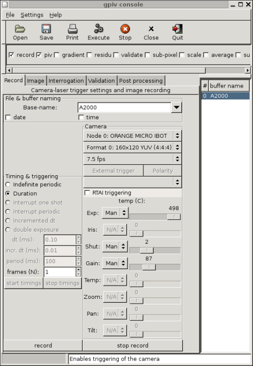
Figure 2.1 Gpiv console with image recording tabulator. This tab may (partly) be absent, depending on the configuration options during the building of the program
2 GPIV
2.1 Starting up
Gpiv may be launched in different ways. In case it needs to trigger
the lasers and camera, the RTAI and gpivtrig Linux kernel modules will
have to be loaded (and unloaded after closing Gpiv). The gpiv_control
script (from the gpivtrig package, which also includes the gpivtrig
module) might be used: "gpiv_control "gpiv [OPTION1]
... [IMAGE1] ..."". Gpiv_control has to be run with root
privileges. In case no trigering is used or if the modules have
already been loaded in the kernel, starting the application is
straightforward with: "gpiv [OPTION1] ... [IMAGE1] ...". If the
modules have not been loaded in the kernel, a warning message will be
displayed and the trigger services will be disabled.
The Gpiv console consists a menu bar, a tool-bar, process
toggle-buttons, a tabulator and a data buffer list (Figure 2.1). At the bottom of the console you can
find an application bar that displays information of the highlighted
item as well as a progress bar that displays the progress of the
running process.
Gpiv reads its default program parameters from ~/.gnome2/gpiv
following the GNOME mechanism. These parameters are defined frome the
Settings->Preferences from the console menu's and may be overruled by
command line keys for the current session. (Invoke "gpiv --help" or
"man gpiv" for information about the command line options.) Apart from
the Gpiv parameter settings, there are also variables to ease the use
of the program, which can not be defined by command line keys. These
variables are stored from previous sessions (like the last displayed
tabulator, image base-names during recording or the last selected
image-name during loading with File->Open). The PIV process variables
that are used for recording, interrogation, validation and
post-processing are read from ~/.gpivrc or from the system-wide
available gpiv.conf (mostly installed at /etc/ under Unix/Linux)
respectively. These process variables are shared with the programs
from the Gpivtools package.
2.2 Menu and toolbar
The menu bar consists general tasks for Gpiv, like file-handling,
preferences and help menus. Underlined characters represent the ALT
short-hand key for launching the menus.
The "File" menu contains "open", "save", "save as", "close" for
reading, storing, and closing data and "exit" for closing the
application. For reading and saving images and data, Gpiv uses the
Gnome Virtual File System (GVFS). This allows you to load data from an
other system (server) you have access to, like ftp or ssh. Loading
data from a server is done by typing Ctr+L when the filebrowser
is open and typing, for example:
ssh:///my_other_account@another_system:image.png
or from Nautilus (see below).
The native image format for Gpiv is the Portable Network Graphics (PNG) format. Image data may also be read to or stored from raw binary data (name.r) that is accompanied by an ASCII header file (name.h) or HDF5 (name.gpi). Images of formats that use lossless compression (tif, gif, pgm, bmp) are converted to PNG during the loading to guarantee the storage of all header information. To save disk space, the original image will be deleted. In case of cross-correlation, it is expected that the second frame is attached to the first image frame. This may be performed manually with gpiv_combing from the Gpivtools package.
The maximum image dimensions that may be used are defined in
gpiv_gtk.h by IMAGE_WIDTH_MAX and IMAGE_HEIGHT_MAX or by the options
--enable-img-width and --enable-img-hight of the ./configure script.
The maximum image dimensions can not be changed during execution of
Gpiv. In case the image dimensions are larger, ./configure will have
to be executed (or gpiv_gtk modified) and Gpiv will have to be
recompiled. In case IMAGE_WIDTH_MAX and IMAGE_HEIGHT_MAX will have to
be redefined, it is recommended to set them at the minimum needed
values in order to save RAM memory usage.
After loading, the file basename is displayed in the buffer list and
the complete image name is displayed in the "Image Info" tabulator of
the console. A display window (or viewer) is launched that shows the
image together with the interrogation area's and its name is displayed
in the application bar of the viewer as well (Figure 2.2.
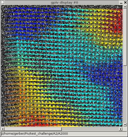
Figure 2.2 Buffer display
containing image, Interrogation Area contours and data
Saving the image and data is done in PNG, raw binary or HDF5 format, depending on the program settings or start-up keys (--hdf and --hdf_img). Image data may also be loaded from the Gnome filemanager NAUTILUS with the "open with.." popup menu or by "drag and drop" of the selected images into the buffer list in case Gpiv has already been launched. Typing Ctr+L or from the Go->Location... menu of Nautilus, the filemanager can be connected to another system or server by using GVFS.
The settings menu contains the menus "gpiv buttons" and "tabulator" to (un)display these parts of the console and "preferences" for defining all Gpiv settings. Closing the "preferences" menu with "OK" stores the settings for future sessions. "Apply" only affects the current session. When settings for the buffer display have been changed, they will be broadcasted to all display windows when "OK" or "Apply" are pressed. "Cancel" closes the preferences window without action. Some parameter settings (image width and image height) need to restart Gpiv. You will be acknowledged in that case.
The "help" menu contains "show tooltips" for obtaining additional help. Tooltips are small windows that pop up when an item is highlighted and contain more extended information about the item than can be displayed in the short line of the application bar. The "manual" menu shows this document. "About" gives short info concerning this application.
The toolbar is a quick way for opening / saving / closing images and
data, executing / stopping processes that are enabled by the process
toggle buttons, which are found below the toolbar, for closing
buffers and for exiting the program.
2.3 Process toggle-buttons
The process toggle-buttons may be switched on in order to define a
chain of processes (pipeline). These processes include recording,
image processing, image PIV interrogation, validation and
post-processes of the PIV estimators. The parameter settings of the
processes are defined in the tabulators of the Gpiv console. The
pipeline process is invoked by the "Execute" button on the toolbar
and, eventually, interrupted by the "Stop" button.
2.4 Buffer list and display window
The buffer list shows a number and the file basename (i.e. the
filename without directory name and extension) of the loaded
images. Images may be loaded directly into the buffer list by means of
"drag and drop" from the Gnome file-manager NAUTILUS. A single buffer
may be selected by pointing to it and left mouse clicking. Several
buffers may be selected by clicking the first and last buffer while
holding the "Shift" key. The execution of processes will than
be performed on every selected buffer. The selected buffers will be
closed following the Window manager protocol (mostly by pressing
Ctrl-W).
For each buffer, a display window is launched that contains the image,
squared frames that represent the contours of interrogation areas
during the initial and the final step of an iterative interrogation
process, a vector field representing the PIV estimators and solid,
coloured, squares expressing the magnitudes of derived scalars
obtained from the PIV estimators by post processing. The interrogation
areas are highlighted when the pointer moves over them. At the bottom
of the display window an application bar shows information concerning
the data. If displaying of interrogation area frames is disabled,
image intensities are shown. Else, the centre point of the highlighted
interrogation area and, eventually, values of the PIV estimators and
its derived quantities are shown. If the settings of Interrogation
Areas are changed or, for some other reason not in accordance with the
settings the PIV data have been generated, the PIV values will not be
displayed. The same information is displayed in the application bar of
the Gpiv console as well. A menubar at the top of the window shows
options for changing the settings for the displaying of the data in the
individual buffer window. When clicking the right mouse button when
pointing within the display, a menu pops up with identic functions as
the menubar. Zooming and moving (paning) the image and data may also
be performed by the mouse scroll button and moving the pointer (when
mouse select is set to "None" in the console) while pressing the left
mouse button. In case the display settings will have to be adjusted
for all open buffers, change the settings from the
Settings->Preferences menu in the Gpiv console. Then, the new settings
will be updated to all buffer windows when "Apply" or "OK" is pressed.
2.5 Tabulator
The tabulator contains pages with parameter settings and buttons to
invoke the processes for image recording, information, processing and
interrogation, PIV-data validation and post-processing. Some of these
pages may be missing, depending on the options during the compilation
of the program.
2.5.1 Record
The most left tabulator 'Record' (Figure 2.1)
contains all settings for the triggering of the lasers the
camera. This tabulator may only show the widgets for triggering or
camera or may be completely absent. This is defined by the compilation
options of the program. Triggering is performed by a Linux kernel
module from the Gpivtrig software package which sends its trigger
pulses over the parallel port. It uses the RealTimeLinux Application
Interface (RTAI), which is a real
time micro kernel to perform processes at accurate timings,
independently of the computing load of the system.
The base-name of the images to be recorded are defined in the
entry. The last 5 names that have been used during the actual or
previous Gpiv sessions are stored. The name may be extended with the
current date and time.
Different timing schedules may be used. For PIV, "Indefinite", "Duration"
and "Double exposure" are most relevant. "Indefinite" will continue until
"stop timings" button (or "Stop" button from the main tool bar of the
application) is pressed. The images are displayed and updated in frame
buffer #0. This setting is convenient for pointing, adjusting and
focussing the camera. For the other timing settings, images are stored
in subsequent buffers, starting at #0. A maximum of GPIV_NIMG_MAX
(defined in gpiv.h of Libgpiv and currently set to fourty) buffers
may be retrieved. Duration will only send a limited amount of trigger
pulses as defined in "frames (N)".
TODO "Interrupt" ...
"Increment dt" will increase the timing of pulses to the lasers as
defined in "inc. dt (ms).,
TODO "double exposure" ...
"Dt" represents the time beween two laser pulses of an image-pair.
The camera uses the IEEE1394 (Firewire), IIDC-compliant protocol. The
"Node.." menu selects the camera if different cameras are connected to
the computer. All other menu-options and settings that belong to the
selected camera are updated and enabled / disabled
automatically. "Format .., selects the image format, "... fps" the
frame rate, TRIGGER MODE ...", "Exp", "Iris", "Shut", "Gain", "Temp",
"Zoom" "Pan" and "Tilt" are obvious.
Enabling "RTAI trigerring" will use the application's trigger
system. If "record" and "stop record" are pressed, the recording of
images and the triggering is started and stopped.
2.5.2 Image
The 'Image' (Figure 2.3) tab displays
information of the image. Some settings, like image file name,
correlation type, image dimensions and image colour depth are only
displayed for informative purposes and can not be changed. The image
filename is determined during recording or loading the image. The
image dimensions, correlatation type and colour depth may be modified
from the Gpiv settings or from the command line keys. During loading
of an image it is checked whether the image header info is in
agreement with these settings.
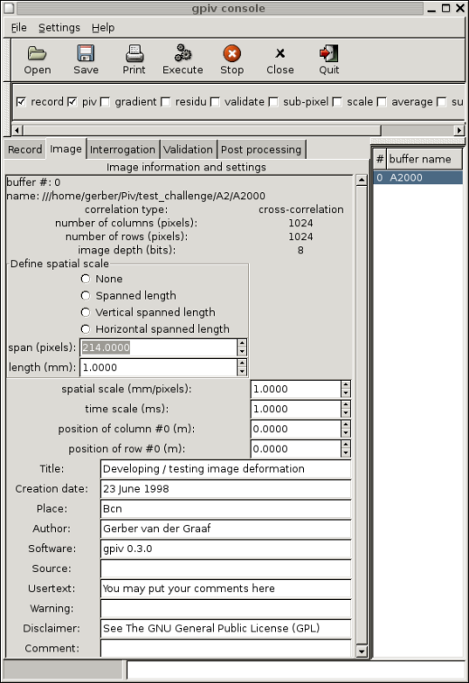
Figure 2.3 GPIV console with image information
tabulator
Time scaling, spatial scaling, the positions of row #0 and column #0
(related to a typical location in the experiment) are identic as in
the Post processing tabulator. These parameters are used for scaling
and positioning the PIV data.
Spatial scaling may be determined interactively by pointing a ruler in
a image. The number of pixels that are spanned by the imaged ruler may
be obtained in arbitrary, horizontal or vertical direction by
activating the subsequent radio buttons. Entering the viewer, then,
will change the pointer image to cross-hair. Pressing and holding the
left pointer button within the image starts drawing a straight line
and shows the pointer position in the application bar. By releasing
the pointer button, the straight line disappears, the span length is
written to the "span" entry and the "spatial scale" entry is updated
for the new value. When pointing in arbitrary direction, Pythagoras'
rule is applied for calculating the correct spanned length by the
ruler image. The length of the ruler that has been spanned, expressed
in mm, will have to be specified manually. Changing this
value will automatically update the "spatial scale" value, as well. If
"span" or "length" are not changed, the spatial scale setting, like
all other image header information and process settings, is read from
the system wide gpiv.conf or from ~/.gpivrc during launching Gpiv.
The items Creation Date, Author, Usertext, Copyright, Software,
Source, Warning, Disclaimer and "Comment" are typical header
text, often recognised, for example, in PNG formatted images.
2.5.3 Process
The 'Process' tab (Figure 2.4)shows the
settings for some image processing that are often used for PIV.
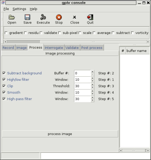
Figure 2.4 Gpiv console with the Image processing tabulator
An image process is enabled by clicking the check button. A variable
is set in the spinner. As a sequence of image processing steps is
non-linear, the order of the processes do matter. Therefore, a step
number indicates when the process will be invoked. These numbers are
automatically set when enabling the process. Disabling an individual
process will re-adjust the step numbering of other enabled processes.
2.5.4 Interrogation
The 'Interrogation' tab (Figure 2.5a, b)show all the
settings for interrogation an image (pair).
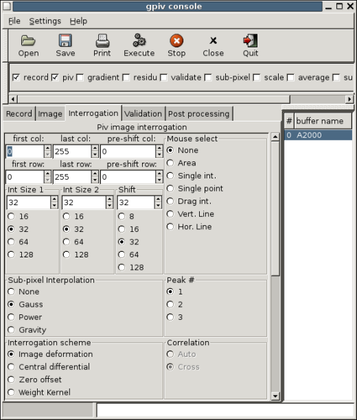
Figure 2.5a Gpiv console with Interrogation tabulator, upper part
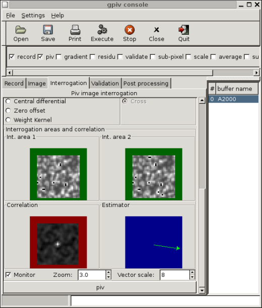
Figure 2.5b Gpiv console with Interrogation tabulator, lower part
- The upper-left corner of the image represents pixel # (0,0). The starting point (first col/row) and the end-point (last col/row) of the image to be interrogated may be defined in the entry-fields as well as a global pre-shift in horizontal (pre-shift col) and vertical (pre-shift row). The first column and row, as defined in the entry's will always be included in the interrogations. The last column/row of the image to be analyzed depends on Interrogation Area sizes and shifts, but will never exceed the last column/row as defined in the entry-fields.
- The size of the interrogation area's (I.A.) and adjacent shift, expressed in image pixels, may be defined by entry's (for arbitrary dimensions) or by radio-buttons (which is convenient for power of 2 dimensions) in 'Int. Size 1', 'Int. Size 2' and 'Shift'. The size of the second I.A. has to be equal or larger than the first one in order to perform adaptive dimensions during an iterative interrogation process. Some of the settings in the entries and of the radio buttons, then, may be disabled for manipulation or its value to be entered may be limited. In case adaptive dimensions of the I.A.'s is applied, zero offsetting is enabled and the grid of the nodes at which estimators are calculated, is adapted during each iteration. This will often increase computation speed and the stability of the calculation. Starting by a course grid with I.A. dimensions of 'Int. Size 2' and 50% overlap. During each iteration, the sizes of the I.A.'s and adjacent shifts are halved until 'Int. Size 1' and adjacent shifts as defined in 'Shift' have been reached. The new estimators at the finer grid, used as local pre-shift values for zero offsetting, are obtained from the previous interrogation at a courser grid by linear or, if possible (i.e. an internal node) bi-linear interpolation. Finally, an additional interrogation, then, should guarantee an optimum estimator.
If the settings of I.A.'s are changed after aninterrogation, the PIV values will not be displayed when moving the pointer over the data.
In case zero offset (at an integer number of pixels) is enabled, i.e. a second interrogation is performed with a pre-shift of the local estimator, the new correlation peak is found between -1 and +1 pixels. The 'classic' forward interrogation scheme or a central differential scheme may be used. Interrogation following the central differential scheme is done by displacing the interrogation area of the first image with half the magnitude of the pre-shift value in negative direction and displacing the interrogation area of the second image in positive direction (of identic, integer magnitude).
A linear weight kernel in order to correct for biasing effects that is generated by the estimation of the correlation function.
"Image deformation", "Central differential" and "Zero offset" are iterative processes that continue until the convergence criterium has been reached. The total amount of differences in the estimators between two succesive iteration steps, related to the number of gridpoints, is used as criterium for convergence and amounts to 0.25 pixels (defined by GPIV_EPSI_MIN). The estimators are validated on outliers after each iteration step of the interrogation procedure. Erroneous vectors are subsequently substitued (and re-validated) by the second or third highest correlation peak or by the quantity as specified in "Outliers" in the Validation tabulator.
The Gauss weigthing check button enables weighting of the Interrogation Area's with a Gaussian function. It is believed that this may improve the PIV analyses as the high-frequency signal generated by the abrupt borders of the I.A. is suppressed.
Symmetric Phase Only filtering (SPOF) is applied to the (2-dimensional) correlation function. Only the phase, but not the amplitude, of the correlation is used to determine the displacement peak. SPOF filtering increases the SNR, by generating a high and narrow displacement peak and low side lobes. It might improve the analysis, especially when there are reflections, from boundaries for example, in one of the images are present [3].
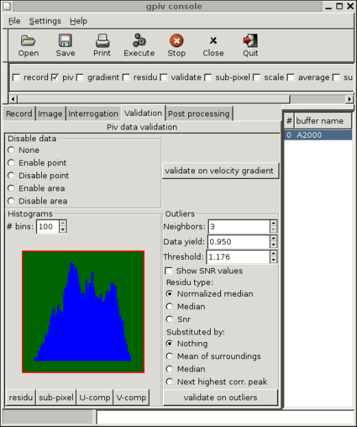
Figure 2.6 Gpiv console with Validation
tabulator
The critical threshold may be filled in manually or may be obtained by invoking "residu" button.
The type of residus may be chosen between "Normalized median", "Median" or "Snr". The normalized median option uses the ratio between the residu (obtained from the actual didplacement and the median displacement from the neighboring data) and between the median residu (resulting from the neighbors). The threshold, then, may be kept at 2 pixels for obtaining a data yield of 90% [2]. This setting should be advantageous if turbulence is heterogeneous within the area of observation. The median option uses the residu between actual data point and the median displacement from its surroundings.
Outliers may be substituted by the local mean value of the surrounding vectors, by the median value of the surrounding vectors or by the displacement from the next highest correlation peak. Unless "Nothing" has been choosen, the data will first be substituted subsequently by a PIV estimator from the next highest correlation peak, the median displacement value, and local mean. If the residu still exceeds the threshold after trying these substitutions, the PIV estimator will be substituted by the preferred option as enabled here.
Finally, the validation on outliers is performed by pressing the
"validate on outliers" button or by enabling "validate" in the process
toolbar of the Gpiv console and pressing "Execute". Validation is also
performed after each step of the interrogation procedure if the
Interrogation scheme is set to "Image deformation", "Central
differential" or "Zero offset". The function of testing on outliers
and substituting is similar to that of the command line program
errvec of the Gpivtools package.
2.5.6 Post processing
The "Post processing" tab (Figure 2.7) contains
tools to apply modifications on PIV estimators and to calculate
derived quantities from the PIV estimators.
Vorticity, shear and normal strain may be derived from the PIV estimators with different numerical schemes; Central differential scheme, Least squares, Richardson and the Circulation method (only for the calculation of vorticity). The function of this process is similar to the command line program vorstra of the Gpivtools package.
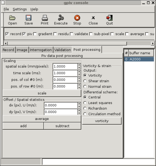
Figure 2.7 Gpiv console with Post processing
tabulator