|
Next: Eularian and Lagrangian approaches Up: Integral equations for the Previous: One, Two and Three Flow Description, Streamline, Pathline, Streakline and Timeline
Streamline, pathline, streakline and timeline form convenient
tools to describe a flow and visualise it.
They are defined below.
Figure 3.6: Streamline definition A streamline is one that drawn is tangential to the velocity vector at every point in the flow at a given instant and forms a powerful tool in understanding flows. This definition leads to the equation for streamlines. where u,v, and w are the velocity components in x, y and z directions respectively as sketched.
Figure 3.7 : Streamtube Hidden in the definition of streamline is the fact that there cannot be a flow across it; i.e. there is no flow normal to it. Sometimes, as shown in Fig.3.7 we pull out a bundle of streamlines from inside of a general flow for analysis. Such a bundle is called stream tube and is very useful in analysing flows. If one aligns a coordinate along the stream tube then the flow through it is one-dimensional.
In a steady flow the streamline, pathline and streakline all coincide. In an unsteady flow they can be different. Streamlines are easily generated mathematically while pathline and streaklines are obtained through experiments. The following animation illustrates the differences between a streakline and a pathline.
Subsections Next: Eularian and Lagrangian approaches Up: Integral equations for the Previous: One, Two and Three University of Sydney |
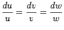 (3.7)
(3.7)