A Source-Sink Pair

Figure 4.21: Source-Sink Pair

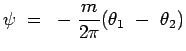
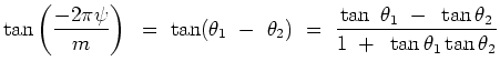
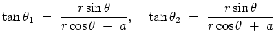
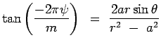
Consider a source and a sink placed at (-a,0) and (a,0) respectively as shown in Fig.4.21. By combining their stream functions we have a stream function for the combination given by,

$\displaystyle \psi = -{m \over {2\pi}}(\theta_1 - \theta_2)$ (4.80)

By taking tangents of the two sides (after manipulation)we have

$\displaystyle \tan \left( -{2 \pi \psi} \over m \right) = {\tan
 (\theta_1 - \t...
...} = {{{\tan \theta_1 - \tan\theta_2}} \over
 {1 + \tan \theta_1 \tan \theta_2}}$ (4.81)

From geometry it follows that
$\displaystyle \tan \theta_1 = {{r \sin \theta} \over {r \cos \theta - a }},   
 \tan \theta_2 = {{r \sin \theta} \over {r \cos \theta + a }}$ (4.82)

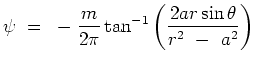
Upon substituting these into Eqn. 4.81, one gets,

$\displaystyle \tan \left( -{2 \pi \psi} \over m \right) = {{2ar \sin
 \theta}\over {r^2 - a^2}}$ (4.83)

so that
$\displaystyle \psi = -{m \over{2\pi} } \tan^{-1} \left( {2ar \sin \theta} \over
 {r^2 - a^2}\right)$ (4.84)

Figure 4.22: Flow about a Source-Sink Pair

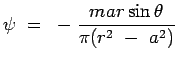
When the distance between the source and the sink becomes smaller, i.e., a is small we have,

$\displaystyle \psi = -{{m a r \sin \theta } \over {\pi (r^2 - a^2)}}$ (4.85)

The streamline pattern for the source-sink flow is sketched in the Fig.4.22.

(c) Aerospace, Mechanical & Mechatronic Engg. 2005
University of Sydney