|
|
Vortex Lattice Method (3-D) |
SOFTWARE DOWNLOADS |
|
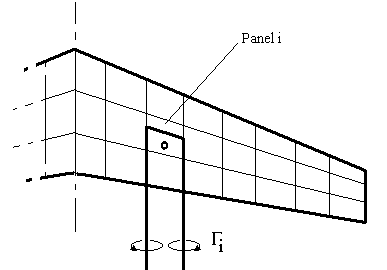
A solution for three-dimensional wings of any general form can be obtained by using a vortex lattice model. For incompressible, inviscid flow, the wing is modelled as a set of lifting panels. Each panel will contain a single horse-shoe vortex. A bound vortex is located at the panel 1/4 chord position with two trailing vortex lines shed from each end. |
|
|
|
Both span-wise and chord-wise variation in lift can be modelled as a set of step changes from one panel to the next. |
|
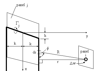
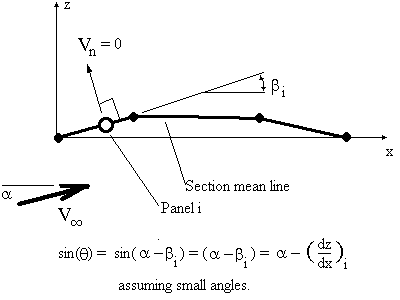
The required strength of the bound vortex on each panel will need to be calculated by applying a surface flow boundary condition. The equation used is the usual condition of zero flow normal to the surface. For each panel the condition is applied at the 3/4 chord position along the center line of the panel. The normal velocity is made up of a freestream component and an induced flow component. This induced component is a function of strengths of all vortex panels on the wing. Thus for each panel an equation can be set up which is a linear combination of the effects of the strengths of all panels. A matrix of influence coefficients is created which is multiplied by the vortex strengths and equal to a right hand side vector of freestream effects. |
|
|
|
|
|
|
|
The influence coefficient Aij will represent the induced flow on panel i due to the vortex on panel j. If all panels are assumed to be approximately planar then this influence coefficient can be calculated as a relatively simple application of the Biot-Savart law along the three component vortex lines. |
|
|
|
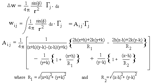
The result of this integration leads to the following formulae for influence coefficients in general. |
|
|
|
The right-hand side terms for the boundary condition equations will depend upon the freestream velocity, the angle of attack for the wing and the slope of the panels due to camber effects. |
|
|
|
A solution for the strength of the vortex lines on each panel is found by solving the matrix of equations. |
|
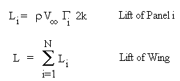
The lift coefficient for the wing at a given angle of attack will be obtained by integrating the panel lift distribution. The lift on a particular panel can be found using the Kutta Law. |
|
|
|
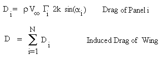
The downwash velocity induced at on a panel can be calculated once the strength of the wing loading is known. The variation between local flow angles for the panel and the freestream velocity can be found. A consequence of this downwash flow is that the direction of action of each panel's lift vector is rotated relative to the freestream direction. The local lift vectors are rotated backward and hence give rise to a lift induced drag. By integrating the component of panel lift coefficient that acts parallel to the freestream across the span then the induced drag coefficient can be found. |
|
|
|
The induced flow angle (alpha i) represents the amount of rotation of the lift vector backward and must be calculated from the velocities induced on the bound vortex of the panel by other panels and the freestream. |
|
Pitching moment about the wing root leading edge can be calculated by summing the panel lift multiplied by a moment arm which extends in the x-direction from the leading edge of the wing to the centre of the bound vortex for the panel. |
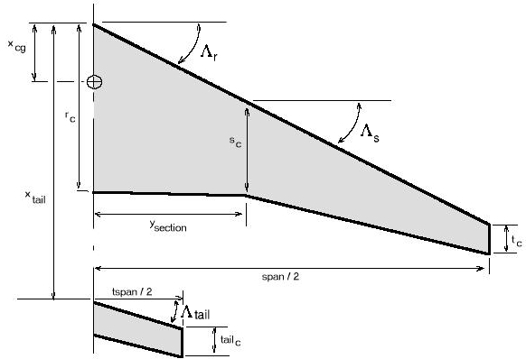
Vortex Lattice Method ProgramThe following computer program allows the user to define wing planforms and geometries. The program assumes a linear variation of planform for up to two zones and a simple planar tailplane. Zone 1 covers wing root to specified span location, then Zone 2 covers span location to wing tip. The section properties can vary linearly across each zone between wing root, mid-span and tip or a contant section can be set for each zone. The wing loading is assumed to be symmetric about the wing root. The tailplane can be set at a required distance behind the wing root with a constant chord and sweep angle. A CG position (faction of root chord behind leading) can be set so that calculated Cm coefficients will be relative to this point |
|
The aerofoil section properties for the wing root, mid-span and tip can be specified by entering a chord length and zero lift angle. This will generate a mean line for each section which corresponds to the input section properties. An incidence angle can be set for the tailplane. |
|
Wing geometry variables :
rc – root chord, sc – section chord, tc – tip chord, origin is at wing root leading edge and CG location is defined as a fraction of the root chord from leading edge. |
|
The program uses the above vortex lattice method equations to obtain solutions for lift coefficient versus angle of attack, pitching moment coefficient versus angle and induced drag coefficient versus lift coefficient2. For a given angle of attack the program will display the resulting differential pressure coefficient distribution. |
|
SOFTWARE Executable Program : Vortex Lattice Method (3-D) (317k)
|
|
References & Resources: "Aerodynamics for Engineering Students" Bertin and Smith, Macmillan 1966. “Extended
Vortex Lattice Model – AVL” Marc Drela,
MIT,2004 |
|
|
|
© AMME, University of Sydney, 1998-2006 |