| Load | (kN) | 26 | 36 | 46.5 | 54.5 | 71 | 75 | 80.5 | 85 | |
| Elongation | (mm) | 0.05 | 0.07 | 0.09 | 0.11 | 0.15 | 0.20 | 0.31 | 0.41 |
| Grade | A | B | C | D |
| Yield (MPa) | 320 | 360 | 410 | 450 |
| Relative cost | 1.00 | 1.09 | 1.14 | 1.20 |
Steel rod is available off-the-shelf in any one of the four grades shown, and in the following diameters (mm) : 2 2.5 3 4 5 6 8 10 12 16 20 24 30
Select a suitable grade and rod diameter for this duty.

What is the maximum load that the assembly can withstand without loss of contact, and what initial force is necessary ?
Hint : Plot vs load the magnitudes of the forces internal to the components. [ 136, 52 kN ]
 0.5 m long bars which are nominally identical and made from a 250 MPa yield steel, are connected by two pins and loaded by a force of 15 kN. The bars were designed on the assumption of equal load sharing and a safety factor of 2.5. However manufacturing inaccuracies lead to the central bar's length differing by 0.2 mm from the outers' length, thus requiring one of the pins to be forced in. Neglecting buckling, determine the actual safety factor of the assemblage if
- the central bar is the longest [ 2.0 ]
- the central bar is the shortest [ 1.6 ]
The
 member consists of a steel rod embedded in a concrete matrix. By itself, the rod would be weak in compression due to buckling; however the compressively strong concrete prevents any buckling. Conversely, concrete by itself would be weak in tension, but the steel component protects it from undue tensile effects. The two components of the composite are thus seen to complement one another.
The member is manufactured and prestressed as follows. The steel rod is stretched by a temporary load Fo, and the concrete poured into a mould surrounding it. When the concrete has set, the mould and the load Fo are removed. Since there is no relative longitudinal displacement between steel and concrete, the steel relaxes somewhat and compresses the concrete - this prestressing occurs before external loading of the composite.
An external tensile load, F, is finally applied to the composite member.
Ascertain the tensile force in the concrete matrix when the composite member is loaded, in terms of the loads Fo and F, together with the longitudinal stiffness of the steel rod, ks, and of the concrete matrix, kc. [ Fconcrete = ( F - Fo )/( 1 + ks/kc ) ]
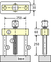 A press consists of the central screw 1 threaded through the beam 2 which is connected to the base by the two identical tie-rods 3. All components are steel; their effective dimensions are
- the pitch of the central screw is 3 mm, its diameter is 20 mm and its length 250 mm;
- the beam is 30 mm wide, 60 mm deep, and spans 250 mm;
- the 250 mm long tie-rods are each 15 mm diameter.
 of radii ri and ro and thickness b, is supported around its outer periphery. A load is transmitted uniformly to its inner periphery by shear. Assuming that the shear in the disc at radius r is uniform, estimate the stiffness experienced by the load if it is :-
- an axial force, F [ 2 π b G / ln ( ro/ri ) ]
- a torque, T [ 4 π b G /( 1/ri2 - 1/ro2 ) ]
 tube is bonded to two identical circular rubber support collars. The allowable shear stress in the adhesive is 100 kPa. An axial force and a torque are applied to one end of the tube as shown.
Use the results of the previous problem to deduce the bond's safety factor.
Values of E, ν are : for plastic 2 GPa, 0.35; for rubber 2 MPa, 0.5. [1.05]
The radial thickness of the material is 0.7 mm before inflation. By how much will the thickness change after inflation if the moduli of elasticity and of rigidity are 3.5 and 1.4 GPa respectively ? [ 0.2 mm ]
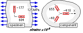 A tensile testat 125 MPa is conducted on a specimen of a component's material. Strain gauges attached to the specimen and to the component in service indicate the strains shown.
Find the principal stresses in the loaded component.
[ -80, 120 MPa, -70o ]
 circumferential stresses in the shaft are compressive, of magnitude p, as sketched for a typical element.
Using the maximum shear stress failure theory, derive the design equation for a shaft cross-section of section modulus Z, loaded by such a pressure in addition to a bending moment, M, and a torque, T.
[ n √{ (M/Z + p)2 + (T/Z)2 } = S ]
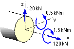 The components of the stress resultant at a particular cross-section of a 50 mm diameter ductile rod are as shown - a tensile force of 120 kN, a vertical shear force of 120 kN, a bending moment of 0.5 kNm and a torque of 1.5 kNm.
What is the maximum equivalent stress at this cross-section? [ 292 MPa ]
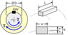 is w x h, its length is L, and it is made from a ductile material whose design tensile stress is S.
The key is provided to transfer the load torque T between the shaft and the collar (eg. the boss of a pulley or gear). The key is fitted closely into slots machined in these components, whose common interface diameter is D, where D >> h.
Identify the modes by which the key may fail, and derive the corresponding design inequalities which must be satisfied by the dimensions.
- σx = 80 ; σy = 170 ; τxy = 60 c.w. [ 50, 200 MPa, 116.6o ]
- σx = -220 ; σy = -70 ; τxy = 180 c.c.w. [ -340, 50 MPa, 56.3o ]
- σx = -205 ;
σy = -445 ;
τxy = 35 c.w.
[ -450, -200 MPa, -8.1o ]
- plane stress, ductile material with yield strength of 500 MPa
- via distortion energy theory, or [ 2.77, 1.36, 1.28 ]
- via maximum shear stress theory [ 2.50, 1.28, 1.11 ]
- as (a), but plane strain ( ν = 0.3 )
- via distortion energy theory, or [ 3.59, 1.46, 1.98 ]
- via maximum shear stress theory [ 3.33, 1.28, 1.96 ]
- plane stress, brittle, with 250 and 800 MPa ultimates [ 1.25, 1.78, 1.78 ]
- as (c), but plane strain ( ν = 0.2 ) [ 1.25, 1.78, 1.78 ]
- σe2 = σ12 - σ1σ2 + σ22 where σ1 and σ2 are the biaxial principals, or
- = σm2 + 3 σa2 in terms of the 'basic' components, or
- = σx2 - σxσy + σy2 + 3 τxy2 in terms of the Cartesian components.
Plot the failure locus in ( σ1, σ2 ) space and superimpose the failure locus of the maximum shear stress theory for plane stress.
Prove that any maximum of z must occur either at x = 0 or at x = L - a result which will be found very useful.
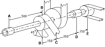 A uniform solid shaft ABCDE is supported in bearings at A and D, and rotates at 900 rev/min (rpm).
50 kW are delivered to the shaft through the 560 mm diameter belt pulley at C. 30 kW are extracted via the 280 mm diameter pulley at B, and 20 kW at the 210 mm diameter pulley at E. At each pulley, the two belt strands are parallel and the ratio of tensions in them is 3:1.
Determine the minimum acceptable shaft diameter if the design stress of 100 MPa incorporates an allowance for fatigue. [ 40 mm diameter ]
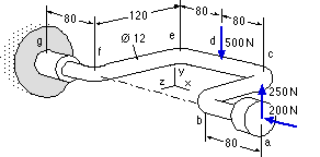 The drill brace abcdefg is made from a bent rod of 450 MPa yield steel, and is loaded as shown by the operator. The simple support at g also provides the torque reaction necessary for equilibrium.
What is the factor of safety?
[ maximum shear stress 1.21; or distortion energy 1.22 ]

| 
|
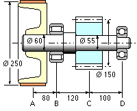
Ascertain the shaft's safety factor when transferring 20 kW from belt to pinion at a steady 7.5 Hz, taking the yield strength of the ductile shaft material to be 500 MPa. Fatigue and stress concentration are neglected here - a large safety factor caters (?) for this neglect.
[ maximum shear stress 14.5 or distortion energy 15.6 ]