Select, for example, an ABB MBT 132M squirrel cage motor, whose rating is 7.5 kW at 1440 rpm.
The duty factor will be 1.2 from the table above; the belt drive should be capable of handling the full motor output, so the design power for the drive will be 1.2 ∗ 7.5 = 9 kW.
Wedge belts are unsuitable for V- flat drives; the V-belt carpet diagram indicates that either A or B belts are appropriate. This first candidate solution will be based on B belts.
From Table 1, Δ = 14 mm and so D2 = 500+14 = 514 mm
The motor pulley must be around 514 ∗ 500/1440 = 179 mm. Take nearest standard : D1 = 180 mm so that the reduction is R = 514/180 = 2.86 and the belt speed is v = [ πD n ]1 = π ∗ 0.18 ∗ 1440/60 = 13.6 m/s
Geometry : Lacking anything definite regarding layout, take C ≅ 2 ∗ 180 √ ( 2.86+1 ) = 707 mm
From ( 2a) L ≅ 2544 mm, so select nearest standard L = 2500 mm
It follows from ( 2b), ( 2c) that C = 685 mm and 2γ = 0.493 rad.
The belts will slip first on that pulley with the lesser fθ product, so from ( 3) and ( 4b) with μ = 1/6 :-
for the small pulley [ fθ ]1 = ( π - 0.493 ) ∗ (1/6) cosec19o = 1.356
for the large pulley [ fθ ]2 = ( π + 0.493 ) ∗ (1/6) cosec90o = 0.606
. . . . that is, the large flat pulley is limiting and kθ = 1 - e - ( fθ )min = 1 - e -0.606 = 0.454
Applying ( 5a) with say z=3 belts as a trial :
P/ kθvz = 9E3 /0.454 ∗ 13.6 ∗ 3 = 487 N
ρv2 = 0.1666 ∗ 13.62 = 31 N - so
( L/vT ) = [(487 +62.72/0.17 +31)/5535 ]11.11 + [(487 +62.72/0.514 +31)/5535 ]11.11 = 1.15 E-9 no units
T = 2.5/13.6 ∗ 1.15 E-9 = 44 khr which is acceptable.
So the choice of 3 B2500 belts is vindicated. This solution candidate is one of many which the drive design program V-belts is capable of generating - refer to the dialogue for this example.

A hinge location at (100, -180) seems appropriate and is therefore selected.
From ( vi), with φ = 90o : s = 137 mm ; t = 57 mm.
In terms of normalised tensions, we have from ( 6), ( 4a) and ( 3) :
( a) 57 fmax + 137 fmin = 100 mm
( b) fmax - fmin = P / W v
( c) fmax / fmin ≤ e ( f θ)min = 1.83
The mass of the motor itself is 50 kg. Allowing around 15% extra for pulley and base, and presuming spring augmentation to be unnecessary, then Wv = 7.6 kW in ( b).

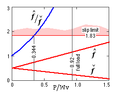
The variation of the normalised tensions, as the power transmitted through the drive increases, is plotted here - values being calculated from ( a) and ( b) simultaneously. Full load corresponds to the power reaching 7 kW, whereupon the RHS of ( b) is 7/7.6 = 0.92.
It is clear from the graph that this value cannot be attained, because gross slip will occur when the ratio of tensions reaches a value of 1.83 - that is when P/Wv = 0.344 and the transmitted power is 0.344 ∗ 7.6 = 2.6 kW. The diagram thus really terminates at the 0.344 abscissa.
Thus the drive candidate is unsuitable because the arbitrary choice of the hinge point means that slip will prevent attainment of full load. The choice of suitable hinge points is left as an exercise for the reader, a problem at the end of the chapter being devoted to this.