EXAMPLE
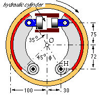
The two shoes of the internal brake are identical. The lining is 40 mm wide and the coefficient of friction is estimated to be 0.35. The brake is hydraulically operated - the maximum available hydraulic pressure is 8 MPa, and the piston diameters are 18 and 10 mm for left and right shoes respectively.
Find the torque capacity of the brake if the lining mean pressure is limited to 400 kPa.
What are the corresponding bearing reactions and brake sensitivity ?
- common shoe geometry
- inclination of x-axis to vertical, φ = arctan 30/72 = 22.6o
P-inclination θP = 90 - φ = 67.4o
lining limits θ1 = 45 - φ = 22.4o ; θ2 = 180 - 35 - φ = 122.4o
from ( 10) Is = 1.460 ; Iss = 1.275 ; Isc = 0.284
OH = a = √ ( 722 + 30 2 ) = 78 mm ; a/r = 0.78
from ( 6b) m = ( 1/μ) ( a/r) ( Iss /Is ) = 1.946 and n = 1 - ( a/r) ( Isc /Is ) = 0.848
- individual shoe parameters
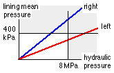 As the hydraulic actuation pressure rises so does the mean pressure on each lining. It is not clear which pressure bound will limit the brake's performance - the hydraulic pressure or the mean pressure on left or right lining - so evaluate pm on basis of a convenient reference hydraulic pressure of 1 MPa say, then scale as necessary.
The left column of figures below for each shoe is based on this reference; the right column comprises the scaled values.
Results are given at length to facilitate checking; two figures at most are significant.
|
|
|
|
|
|
| LEFT SHOE
| RIGHT SHOE
|
|
|
|
|
| Shoes are internal so Δ = -1
| trailing so δ = +1
| leading so δ = -1
|
|
|
|
|
| P
| =
| ( pA )hydraulic
| 255
| 1858
| 79
| 573
| N
|
|
|
|
| M
| =
| Pe { e = 75+72 mm }
| 37.4
| 273
| 11.6
| 84
| Nm
|
|
| (12)
|
| λ
| =
| M/brake actuation (pressure)
| 37.4
|
| 11.6
|
| Nm/MPa
|
|
| ( 6b)
|
| No
| =
| M/( μrIs ( m - δΔn ))
| 262
| 1912
| 206
| 1503
| N
|
|
| ( 5b)
|
| pmax
| =
| No /wr
| 65.5
| 478
| 51.5
| 376
| kPa
|
| **
| ( 9)
|
| pm
| =
| pmax Is /( θ2 - θ1 )
| 54.8
| 400
| 43.1
| 314
| kPa
|
|
| ( 5b)
|
| Fx
| =
| No ( ΔIsc - δμIss )
| -191
| -1396
| 33
| 244
| N
|
|
| ( 5b)
|
| Fy
| =
| No ( δμIsc + ΔIss )
| -308
| -2248
| -283
| -2065
| N
|
|
| ( 5b)
|
| T
| =
| μrIsNo
| 13.4
| 98
| 10.5
| 77
| Nm
|
|
| ( 8)
|
| η
| =
| 1/( m - δΔn )
| 0.358
| 0.358
| 0.911
| 0.911
|
|
|
| ( 8)
|
| S
| =
| m/( m - δΔn )
| 0.696
| 0.696
| 1.772
| 1.772
|
|
| **
| On the basis of 1 MPa hydraulic pressure, the greater mean lining pressure is 54.8 kPa, so a hydraulic pressure of 1 x 400/54.8 = 7.30 MPa will correspond to the maximum allowable lining pressure and hence to maximum torque capacity. The hydraulic pressure capacity is adequate, ie. torque capacity is not limited by it, and a relief valve will be necessary in the circuit, set at 7.3 MPa, to ensure that the lining pressure does not exceed 400 kPa. Multiplying results in the left column for each shoe by 7.3 gives the final values in the right column - though the mechanical advantage and sensitivity are not affected by the actuation.
|
The mechanical advantage of the brake - the overall transformation of pressure to braking torque - is :-
ηo = 13.4 +10.5 = 23.9 Nm/MPa [ ie. ( 98 +77 ) /7.3 Nm/MPa ]
In this problem the actuating linkage factors λ represent (brake actuation pressure)- to- (shoe actuation moment) transformations ( Nm/MPa), so from ( 13) the brake overall sensitivity is :
So = Σ ληS / Σ λη = ( 37.4x0.358x0.696 + 11.6x0.911x1.772 )/( 37.4x0.358 + 11.6x0.911 ) = 1.171
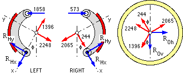
Hinge and drum shaft reactions may be found from free bodies complete with the shoe/drum contacts calculated above from ( 5b). Torques are not shown as only force equilibrium is being considered. Here the contact Fx, Fy are drawn on the shoes in their correct senses from above; the reactions to these appear on the drum free body.
For force equilibrium of these free bodies :
| Left : | ΣFx | = | RHx - 1396 + 1858 sinφ | = | 0 | ; | RHx | = | 681
|
|
| | ΣFy | = | RHy - 2248 + 1858 cosφ | = | 0 | ; | RHy | = | 533
| | RH | = | 865 | N left
|
| Right : | ΣFx | = | RHx + 244 + 573 sinφ | = | 0 | ; | RHx | = | -464
|
|
| | ΣFy | = | RHy - 2065 + 573 cosφ | = | 0 | ; | RHy | = | 1536
| | RH | = | 1605 | N right
|
| Drum : | ΣFv | = | ROv + ( 1396-244) cosφ - ( 2248+2065) sinφ = 0
| ; | ROv | = | -595 |
|
| | ΣFh | = | ROh + ( 2065-2248) cosφ - ( 1396+244) sinφ = 0
| ; | ROh | = | -800
| | RO | = | 997 N
|
summary
| | Actuating pressure | : | 7.3 | MPa | | Braking torque | : | 175 | Nm
|
| | Sensitivity | : | 1.17 | | | Drum shaft reaction | : | 997 | N
|
| | Shoe hinge reactions | : | 865 N (left), 1605 N (right)
|
The Macintosh program Brakes analyses twin rigid shoe brakes in this manner - the reader may refer to the dialogue corresponding to this example.
 Copyright 1999-2005 Douglas Wright,
doug@mech.uwa.edu.au
Copyright 1999-2005 Douglas Wright,
doug@mech.uwa.edu.au
last updated May 2005