A brake is incorporated into the motor shaft. Determine the brake torque and average power over the braking period when stopping within 1 m, a load of 1 t (1 tonne) being lowered at 3 m/s. [ 435 Nm, 26.1 kW ]
 |
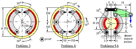
Duty statements are [ psi ≡ lbf/in2; 1000 lbf/kip ] :
| problem | 3 | 4 | 5 | 6 | |
| friction coefficient | 0.32 | 0.24 | 0.3 | 0.3 | |
| braking torque | - | - | - | 25 kip.in | |
| actuation force | 1.2 kN | - | 400 lbf | - | |
| lining mean pressure limit | - | 1.0 MPa | 150 psi | - | |
| lining width | 28 mm | 75 mm | - | 1.7 in | |
| Solutions | |||||
| braking torque | 231 Nm | 2646 Nm | 2150 lbf.ft | - | |
| actuation force | - | 8604 N | - | 404 lbf | |
| lining mean pressure | 543 kPa | - | - | 125 psi | |
| lining width | - | - | 1.7 in | - | |
| sensitivity | 1.337 | 1.117 | 1.143 | 1.101 | |
| hinge reaction - left | 462 N | 8900 N | 6540 lbf | 4720 lbf | |
| hinge reaction - right | 2716 N | 8900 N | 4130 lbf | 5925 lbf | |
| drum shaft reaction | 2323 N | 0 | 2510 lbf | 1290 lbf | |
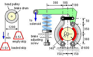
 A skip hoist for lifting bulk material, consists of two identical buckets or "skips" connected by a wire rope which passes around a motor- driven head pulley. The loaded skip is partially counterbalanced by the empty skip. The head pulley is equipped with the brake illustrated, which is so arranged that in normal operation the brake is disengaged by an electric solenoid. In the event of an electrical power failure however, the brake is automatically engaged by a steel compression spring.
 At first glance, a sprag type of over-running, uni-directional clutch looks rather like a cylindrical roller bearing in that it consists of two concentric circular rings. However instead of having cylinders between these, there is a series of closely spaced "sprags" or cams, similar to the one sketched. These fit loosely for one direction of relative ring rotation to allow "free-wheeling". Light springs keep the sprags in touch with the rings. A reversal of relative rotation causes a rocking of the sprags and a tightening-up so that a high torque may be carried.
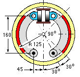
 The centre of mass of a 1.2 t vehicle lies midway between front and rear axles, at a height above road level of one quarter of the wheelbase (the distance between front and rear axles). The vehicle is equipped with hydraulically operated, symmetric brakes as shown, the front and rear sets being identical except for lining width and hydraulic cylinder diameter.