The braked wheel
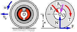
We now investigate the stability of road vehicles whilst braking during straight line motion, and consider first a typical single non-driven wheel equipped with a drum brake of the type examined above. There are three contacts between the wheel/brake drum/tyre system and its surrounds :
- the ground, characterised by a tyre/ground adhesion coefficient k, and represented on the free body by a normal force component N and a friction component F whose sense opposes vehicle translation vO and whose magnitude cannot exceed the adhesion limit Fmax = kN when the wheel slides without rotation on the ground, a condition known as wheel lock
- the two brake shoes, which give rise to the braking torque T and the force resultant R which are proportional to the brake actuation Po as discussed above - provided the wheel is turning since friction force = μ∗normal reaction at the lining- drum contact only when there is relative motion between lining and drum
- the wheel bearing at O, taken to be essentially frictionless so that the sole effect here is the bearing reaction RO.
The equation of angular motion of this system about its centre of gravity O is Frw - T = I dω/dt, and if the system's inertia I is negligible then :
( x) F = T/rw under all conditions.
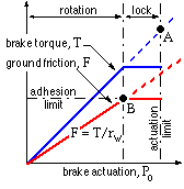
The vehicle decelerating force F and the braking torque T are plotted against brake actuation Po.
In the absence of wheel lock, the torque increases in proportion to actuation, until a limit dictated eg. by a relief valve is reached - this actuation limit is shown as the point A. During this period of brake application, wheel rotation occurs and the decelerating force F also is proportional to Po via ( x).
If a sufficiently small value of either k or N should occur then the adhesion limit is reached at point B, below the actuation limit. The torque produced by the brake is also limited since the wheel is locked and does not rotate - and from ( x) Tmax = Fmaxrw = kNrw . Such a situation occurs when sliding on a gravel road with the brake pedal frantically pressed to the floor - no matter how hard the brake is applied, wheel rotation has ceased and vehicle deceleration is dictated by the (lack of) ground adhesion and not by any limitations of the brake itself or the brake's source of actuation.
Braking of Vehicles
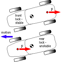
The front wheels of the upper vehicle here are locked by the brakes and slip on the ground. The braking force, F, is thus generated in the main by the rear wheels and its moment about the mass centre tends to correct any yaw, leading to stable braking. Conversely the rear wheels of the lower vehicle are locked so the major braking force is due to the front wheels and tends to increase yaw, rendering braking unstable.
The effect on a single wheel when reduced normal ground reaction N lowers the adhesion limit Fmax has been noted. When a multi-wheeled vehicle decelerates, then the normal reaction on the front wheels increases from its static value, while that on the rear wheels decreases - the amount of increase / decrease depends upon the magnitude of the deceleration and upon the location of the vehicle's centre of gravity. The increase in front wheel reaction increases also the adhesion limit and renders the front brakes relatively more effective (more able to decelerate without front wheel lock), as anyone who has flown over the handlebars of a bicycle will testify!
Motor vehicles are thus provided with front brakes which are more powerful than the rear - achieved by larger lining areas and/or hydraulic cylinders - but if this is overdone then the rear wheels may lock rendering the vehicle unstable as pointed out above.
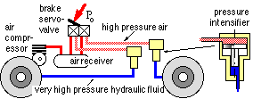 The brake control system for a typical truck is sketched - it consists of separate air and hydraulic fluid circuits. The air is pressurised by an engine driven compressor and driver controlled by a foot pedal operated servo-valve. The air acts over the large piston of the front brake pressure intensifier whose small piston causes the hydraulic fluid circuit to reach very high pressure. A separate intensifier and hydraulic circuit is provided for the rear brakes. This system transforms the driver's braking effort Po into hydraulic pressure in the brake cylinders of front and rear wheels. Thus, provided locking of neither front nor rear wheels occurs, the ratios of front-to-rear braking torques and decelerating friction forces are constant and braking is said to be proportional. Such a high performance braking system is not needed in a car - a single fluid system is adequate.
Although proportional control is straightforward, it is also potentially dangerous if road conditions and deceleration lead to unstable rear wheel lock. The following paragraphs examine this possiblity by considering the interaction between :
- the vehicle, characterised by the location of its mass centre
- the nature of the tyre/road contact, described by the adhesion coefficient k
- the decleration, and
the installed brake control system, which must ensure stable braking, in straight forward travel at least, under as wide a range of road conditions as possible.
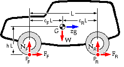
The dimensions which locate the mass centre G of a vehicle are normalised by the wheelbase L. The mass centre is thus defined by cF (or cR since cF + cR = 1) and h. The deceleration normalised by g is z.
Neglecting as small any pitching tendency, the equations of motion are :-
( 20) S Fright = FF + FR = ( W/g) z g = W z
( 21a) S MPF = W cF - NR = W z h
( 21b) S MPR = W cR - NF = - W z h
For a given deceleration z and build - ie. cF, h and weight W - these equations are insufficient to enable determination of the ground contact components. Another physical condition is necessary, which may be either :
- the braking control system, which dictates the front-to-rear braking distribution in the absence of wheel lock, or
- locking of either the front wheels, or the rear wheels, or both front and rear simultaneously.
These conditions must now be considered in order to find out the deceleration achievable with a given vehicle on a given ground surface and more importantly to ascertain whether braking is stable or not.
Wheel lock - the vehicle characteristic
If the front wheels should lock, then, as above : FF = kNF . Similarly if the rear wheels lock, then FR = kNR . Combining these with ( 21a) and ( 21b) in turn, and defining the normalised wheel friction / braking force as f ≡ F/W, results in either :
( 22a) ( 1/k - h ) fF - h fR = cR front wheel lock - stable, or
( 22b) h fF + ( 1/k + h ) fR = cF rear wheel lock - unstable,
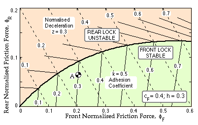
These linear relations describe how the total braking effort is apportioned between front and rear wheels, as either wheel set locks. They are plotted for a class of vehicles whose mass centres are located proportionally at cF = 0.4, h = 0.3.
Also shown on this diagram are the loci of constant deceleration, ie. from ( 20) :
( 23) fF + fR = z
The lines which represent front and rear wheel lock meet in a curve, which therefore corresponds to lock of both front and rear wheels, and which, from ( 22), is given by :
( 24) h ( f F + f R)2 = cF fF - cR fR ; cF + cR = 1
This curve - defined uniquely by the location of the mass centre - is the vehicle characteristic. The deceleration at any point on a z-locus, such as point A, is evidently less than the maximum possible deceleration which is achievable on the characteristic - eg. zmax = 0.3 = k for the point A. As the characteristic represents the locus of maximum possible decelerations, it is sometimes called the "ideal control locus", though it is hardly ideal from the driver's point of view.
The brake control characteristic
The proportional braking mentioned above appears on the diagram as a line of constant slope :
( 25) FR / FF = fR / fF = constant ≤ ( fR / fF )max = cF / cR
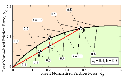
The maximum slope is the slope of the vehicle characteristic at the origin, which would result in unstable braking at all times, if implemented. The sketch illustrates a slope of half this, ie. fR / fF = 1/3 for the vehicle under consideration, and shows how such a plot may be used to assist brake selection for a particular vehicle. Point B represents a modest deceleration of 0.2g, which is stable provided that road conditions allow it, ie provided that k ≥ 0.23. If on the other hand, the adhesion coefficient were 0.3 and the brakes further actuated to give greater deceleration, then point C would be reached, corresponding to a deceleration of 0.27g. At this point the front wheels would start to lock and the proportional braking trajectory BC would give way to the front wheel adhesion locus CD. However since braking is still stable, the point D could be reached - mainly due to an increase in the rear wheels' contribution. At D of course, the limiting deceleration is attained ( z = k = 0.3). This sequence is quite acceptable as the driver would experience feedback of incipient loss of control in the segment CD.
Suppose however that road conditions improved such that k = 0.5 (point E). If the brakes were applied severely, all wheels would lock simultaneously - there would be no warning. It would also be impossible to achieve decelerations greater than 0.5g if road conditions were to further improve (ie. k > 0.5). So simple proportional control is deficient in both these regards, unless the slope is made unacceptably small.
One way of overcoming these drawbacks at little cost is to incorporate an actuation limit such as a pressure relief device in the hydraulic circuit of the rear brakes only, to limit the braking torque and braking effort on the rear treads. Such a brake control characteristic is called proportional- limiting. An example of this is shown below, set to give a maximum rear braking force of 0.095∗vehicle weight, and installed in four different vehicles.
Application of the foregoing arguments demonstrates that such a control characteristic will be stable if it lies under the vehicle characteristic for all road conditions likely to be encountered.
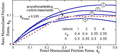
The characteristic of the vehicle previously considered is shown at 1. Characteristic 2 corresponds to a mass centre height increase of L/20. In 3 the mass centre has been moved forward by L/20, whilst both these displacements give rise to the characteristic 4. From this it may be seen that if the original vehicle 1, equipped with the proportional -limiting control scheme illustrated, were loaded in a manner that gave rise to either of these latter two mass centre shifts, then the vehicle would be a potential death trap. A control limitation which is set too low in an attempt to guarantee stability will have an adverse effect in unnecessarily constraining the deceleration which is attainable for any given road surface.
Plotting the vehicle and control characteristics in the above manner enables the effects of different brake control philosophies to be appreciated quickly. Although vehicle brake design in practice is complicated by aspects of real behaviour neglected in the preceding analysis (eg the inertia of the wheel- tyre- drum system may be significant), and by requirements such as braking stability whilst cornering or jack-knife avoidance in the case of articulated vehicles, such an analysis is a necessary first step.
 Copyright 1999-2005 Douglas Wright,
doug@mech.uwa.edu.au
last updated May 2005
 The brake control system for a typical truck is sketched - it consists of separate air and hydraulic fluid circuits. The air is pressurised by an engine driven compressor and driver controlled by a foot pedal operated servo-valve. The air acts over the large piston of the front brake pressure intensifier whose small piston causes the hydraulic fluid circuit to reach very high pressure. A separate intensifier and hydraulic circuit is provided for the rear brakes. This system transforms the driver's braking effort Po into hydraulic pressure in the brake cylinders of front and rear wheels. Thus, provided locking of neither front nor rear wheels occurs, the ratios of front-to-rear braking torques and decelerating friction forces are constant and braking is said to be proportional. Such a high performance braking system is not needed in a car - a single fluid system is adequate.


