EXAMPLE

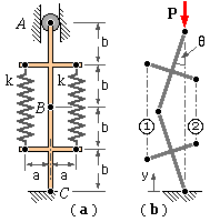
It is obvious that the system is in equilibrium as it stands. If the load had been tensile then no other deformed configuration would be possible; however if the load is compressive the system may not be stable in this undeformed position and other positions must be considered - the loaded configuration of Figure ( b) and its mirror image.
The angle θ is selected as the most convenient measure of displacement in the loaded position Figure ( b). In order to apply ( 1) it is necessary to express, in terms of θ, the PE gain of the deformed system over that of Figure ( a) in which the elastic members are unstrained.
From Figure ( b) the lengths of the springs 1 and 2 are :
L1 = 2( b cosθ + a sinθ ) = 2b ( cosθ + α sinθ )
L2 = 2( b cosθ - a sinθ ) = 2b ( cosθ - α sinθ )
where the constant α = a/b reflects the characteristic proportions of the mechanism.
The corresponding unstrained lengths Lo are found by substituting θ = 0, and so Lo1 = Lo2 = 2b.
The spring deformations are therefore :
δ1 = L1 - Lo1 = 2b ( cosθ + α sinθ - 1 )
δ2 = L2 - Lo2 = 2b ( cosθ - α sinθ - 1 )
and hence the strain energy gain of the two springs ( k1 = k2 ≡ k ) is :
Uk = 1 /2 k1 δ12 + 1 /2 k2 δ22 = 4 k b2 [ ( 1 - cosθ )2 + ( α sinθ )2 ]
For the load, with the base reckoned as the PE datum, the height above datum is : y = 4 b cosθ. The corresponding height in the unstrained mechanism follows with θ = 0 as yo = 4 b. So the gain in potential energy of the load is :
UP = P ( y - yo ) = 4 P b ( cosθ - 1 ) - actually a loss.
The total potential of the system as a whole is therefore :
U = Uk + UP = 4 k b2 [ ( 1 - cosθ )2 + ( α sinθ )2 ] + 4 P b ( cosθ - 1 )
Now we are interested solely in the vanishing first derivative of U, and in the sign of its second derivative. Its absolute size is irrelevant, so U is non-dimensionalised by 8kb2 to give the normalised energy, u :
u = U/8kb2 = 1 /2 [ ( 1 - cosθ )2 + ( α sinθ )2 ] + p ( cosθ - 1 )
where p = P/2bk is the load factor - since 2bk is a known constant, then P may always be found for any given p, and vice versa. This normalising is optional; it is carried out purely to simplify subsequent algebra.
Differentiating :
( A) u' = sinθ [ 1 - p + ( α2 - 1 ) cosθ ]
( B) u" = ( 1 - p ) cosθ + ( α2 - 1 ) cos 2θ
The equilibrium paths, from ( 1a) and ( A) are :
| either | sinθ = 0, ie. θ = 0, in which case, from ( B) : | ||
| u" = ( 1 - p ) + ( α2 - 1 ) = α2 - p | so | if p < α2 then u" > 0 and the path is stable; | |
| if p = α2 then u" = 0 and the path is neutral; | |||
| if p > α2 then u" < 0 and the path is unstable. | |||
| This is the primary (undeformed) path between no load p = 0 and the critical load (factor) pc = α2 | |||
| or | p = 1 + ( α2 - 1 ) cosθ, in which case, from ( B) : | ||
| u" = ( 1 - α2 ) sin2θ | so | if α < 1 then u" > 0 and the path is stable; | |
| if α = 1 then u" = 0 and the path is neutral; | |||
| if α > 1 then u" < 0 and the path is unstable. | |||
| The stability of these secondary ( deformed ) paths is thus dictated solely by the proportions, α | |||

|
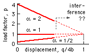
The secondary post-buckling paths are stable for the mechanism for which a = b/2. This behaviour is analogous to that of plates and plate structures.
If a = b then the critical load is 2bk and the secondary paths are neutral - which is the performance noted for Euler columns.
Finally for a = 2b, the critical load is 8bk and the secondary paths are unstable - similar to those of cylindrical shells and similar systems.
In practice, interference would prohibit realisation of the full range of theoretical displacements.
 To verify the stabilitiy of the secondary paths we may find the P-q relations, q being the load displacement. From the geometry and above :
q = yo - y = 4 b ( 1 - cosθ )
Eliminating q between this and the secondary path equation :
p = P / 2 b k = α2 + ( 1 - α2 ) ( q / 4 b ) which plots as shown.
This confirms prior reasoning - the stable path ( α < 1 ) has positive slope, the neutral path ( α = 1 ) zero slope, and the unstable path ( α > 1 ) negative slope.