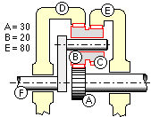
 Tooth numbers of certain gears in the epicyclic train are indicated; all gears are of the same module. Gear A rotates at 1000 rev/min clockwise while E rotates anticlockwise at 500 rev/min.
Determine the speed and direction of rotation of the ring-gear D and of the arm shaft F. If the power output through each of D and F is 1 kW, what are the power transfers through A and E?
[ 371 rev/min anticlockwise; 40 rev/min clockwise; 8.77 kW input; 6.77 kW output ]
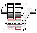 The arm of the epicyclic train is driven clockwise at 1450 rev/min by a 5 kW motor. What torque is necessary to lock the 33 teeth gear? What is the speed of the 31 tooth gear? Note the reduction !
[ 16.3 kNm clockwise, 2.92 rev/min clockwise ]
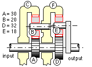 The sun wheels A and D are integral with the input shaft of the compound epicyclic gear illustrated, and the annular wheel C is fixed. The planet wheel B rotates freely on an axle carried by the annular wheel F, and the planet E on an axle mounted on the output shaft's arm. Given the tooth numbers indicated, find the speed of the output shaft when the input shaft rotates at 1000 rev/min.
[ 524 rev/min ]
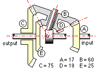 In the epicyclic train illustrated, the gear C is fixed and the compound planet BD revolves freely on a spindle which is coaxial with the input and output shafts.
(a) Show that if zb ze > zc zd then input and output shafts rotate in the same direction.
(b) 7.5 kW is fed into the input shaft at 500 rev/min, losses are negligible, and tooth numbers are sketched. Determine the torque on the output shaft.
[15.5kNm ]
Evaluate the base pitch and the angle γ of Fig A.
[ 103.8, 107.1, 114, 118.8 and 130.8 mm. 17.7 mm, 6.47o ]
[ 108.6 ≤ C ≤ 112.8 mm, 24.47o, 1.42 ]
[ 6 mm module, with 27 and 38 teeth, and profile shifts of 0.45 say, for pinion and correspondingly 0.38 for wheel ]
(a) the pairs 13:35, 23:62 and 36:97 (which approximate the ratio 0.3711 to within 0.1%);
(b)* 23:62 teeth, assuming the minimum practical profile shifts for both gears;
(c)* repeat (b) but use the maximum practical profile shifts.
Comment upon the trends suggested by these results.
| number | allowable stresses, MPa | speed, | ||
| of teeth | contact | bending | rev/min | |
| pinion | 25 | 1100 | 290 | 150 |
| wheel | 55 | 1000 | 280 | - |
Shock loading of the foregoing drive results from unsuspected torsional vibration. If the effective application factor is in fact 1.25, what life may now be expected? [ 5.4 khr ]
Estimate the pair's capacity (kW) for a 10 khr life in a shock-free application in which the pinion speed is 300 rev/min. The transmission accuracy level number is 6. [ 9.1 kW ]
| number | allowable stresses, MPa | speed, | ||
| of teeth | contact | bending | rev/min | |
| pinion | 20 | 1300 | 180 | 90 |
| wheel | 37 | 1250 | 175 | - |
| number | allowable stresses, MPa | speed, | ||
| of teeth | contact | bending | rev/min | |
| pinion | 10 | 1320 | 380 | 200 |
| wheel | 36 | 1100 | 360 | - |
Select suitable tooth numbers and profile shifts, along with a corresponding module and facewidth for a compact pair with a design life of 20 khr.
| contact stress | σc | (GPa) | 1.0 | 1.1 | 0.9 |
| speed | N | (rev/min) | 500 | 400 | 300 |
| duration | t | (hours) | 2 | 1 | 3 |
If power is transmitted to the following cycle, what life may be expected of the pair ?
| power | P | (kW) | 60 | 45 | 35 |
| pinion speed | N1 | (rev/min) | 200 | 150 | 100 |
| duration | t | (min) | 10 | 20 | 30 |