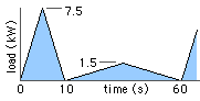
 A load fluctuates cyclically as shown. Determine the mean effective load and select a motor suitable to drive it, using an exponent of (a) 2, (b) 5 in the equivalent load equation.
[ 100 LB, 112 M]
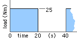 Select a motor to drive a load whose inertia is 0.2 kg.m2 and which varies periodically as shown.
[ 132 S]
Select a motor to drive the fan and estimate the running speed and acceleration time. Check your results with the program 'Motors'.
[ 180M, 1472 rpm, 2.7s ]
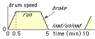
Select a motor to drive the drum through a 5.75 : 1 reduction gearbox.
[ 160 M ]
Assuming the motor torque -speed characteristic at the mean torque, Tm , to be approximately linear with negative slope of 'k' ( Nms/rad ), show that the amplitude of the motor torque excursions, Tv , about the mean, is given by :
Tv / Ta = [ 1 + ( 2π J/ k to )2 ]-1/2 ie < 1.
Discuss the feasibility of the proposal using the results of the previous problem in conjunction with an exponent of 2 in the equivalent load equation ( 3).
 Select a motor to drive a fairground machine which consists of a 5 m diameter rotating drum. The drum loaded with people accelerates for 30s; it then runs at constant speed before slowing to a stop for passenger exchange prior to the next cycle. The motor runs continuously, even while the drum is stationary.
The motor drives the drum through an hydraulic coupling and a 70:1 speed reducer whose efficiency is 75%. The loaded drum's inertia is 10 t.m2. Its power consumption due to friction is negligible, ie. it needs appreciable power only for acceleration.
[ 90 S ]
180, 205, 235, 265, 290, 325, 370, 415, 450, 510, 585, 660, 735, 815, 915, 1040 mm
for which the torque characteristic at small slips is given by :
T ( kNm ) = 0.9 d5 n2 s ( 1.5 - s ) where d is the size (m) and n (rev/s) the impeller speed.
Select a coupling for use with a 132M motor in the drum drive of Problem 4 and determine the speed of the drum. Note that the coupling is interposed between motor and gearbox.
[ 265 mm, 242 rpm ]
|
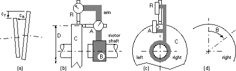
Misalignment may be measured by the arrangement of Fig (b). An arm is mounted on the motor shaft eg. by means of the boss B. Two dial gauges are rigidly attached to the arm, their styli bear upon the coupling half, C :
- gauge R measures radial runout εr resulting from shaft radial misalignment, Fig (a), and
- gauge A measures axial runout εa resulting from shaft angular misalignment.
Radial and angular misalignments are independent of one another, as are εr and εa .
Gauge readings are recorded against rotation angle θ, Fig (d), as the shafts are rotated together slowly by hand. Neglecting any inconsequential mean value, the variation of each (small) runout is sinusoidal : ε = εo cos ( θ - θo ) the amplitude εo and phase θo of which enable correction of the misalignment, radial or angular as the case may be, by means of adjustments to the motor mounting position.
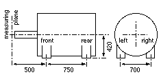
For a particular motor the locations of the shaft and measuring plane in relation to the four mounting bolt positions are sketched.
The following readings [ 1 gauge division = 0.01 mm ] are obtained as above, gauge A readings being taken at the diameter D = 400 mm, Fig (b) :
| angle from vertical, θ (deg) | 0 | 45 | 90 | 135 | 180 | 225 | 270 | 315 |
| reading (divisions) of radial gauge R | 61 | 65 | 43 | 7 | -20 | -22 | -3 | 31 |
| reading (divisions) of axial gauge A | 37 | 26 | 29 | 46 | 69 | 80 | 79 | 61 |
What displacements of the motor mounts are necessary to minimise misalignment ?
[ front 0.77 up, 0.85 right; rear 1.33 up, 1.77 right (mm) ]