EXAMPLE

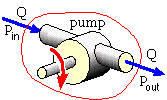
Under test at 500 rpm (rev/min), a centrifugal pump delivers a flow of 0.05 m3 /s against a pressure difference of 350 kPa with an overall efficiency of 70%.
Assuming that rotodynamic machines follow approximate quadratic torque -speed characteristics, select a motor and speed reducer to operate this pump continuously at 600 rpm.
First consider the given test state.
The power delivered by the pump to the fluid is :
Pfluid = flow rate ∗ pressure difference, Δp = Q ( pout - pin ) = 0.05 ( m3 /s) ∗ 350 ( kN/m2 ) = 17.5 kW

The overall efficiency of the pump is essentially : ηoverall = output / input = Pfluid / Pshaft
and so the shaft power necessary to drive the pump must be :
Pshaft = Pfluid /ηoverall = 17.5 / 0.7 = 25 kW which corresponds to a shaft torque of
T = P / ω = 25∗103 (Nm/s) / { 2π ∗ 500/60 (rad/s) } = 477 Nm
At the operating speed of 600 rpm, from ( 1a) the torque necessary to drive the pump is
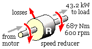
T = 477 ∗ ( 600/500 )2 = 687 Nm
- One might be tempted to choose a motor on this basis, eg. from the above table the 315 SMA with a full load torque of 706 > 687 Nm, but this would be WRONG because it ignores the torque amplification of the speed reducer - choosing a motor on the basis of power rather than on torque is generally less prone to error.
The corresponding power necessary to drive the pump is
P = T ω = 687 (Nm) ∗ { 2π ∗ 600/60 (rad/s) } = 43.2 kW
- Alternatively, since T ∝ speed2 it follows that P = Tω ∝ speed3 for a rotodynamic machine, ie. the power necessary to drive the pump at the operating speed is 25∗(600/500) 3 = 43.2 kW

But the speed reducer is real and will incur losses which must be supplied by the motor. If the reducer's efficiency is taken to be 95 % (see eg. the table in the next chapter) then the required minimum motor power will be
P motor = 43.2 / 0.95 = 45.4 kW
The choice of motor thus appears to lie between the 225 SMB with a rated continuous output of 45 kW and the 250 SMA at 55 kW. Apparently the smaller motor would be overloaded by 1%; it's worth reviewing previous work to see if this can be ignored or eliminated. Factors affecting the choice of motor and reducer include the following :
- The foregoing numbers should not be treated as gospel, since :
- Published motor characteristics might be expected to err on the conservative side, so the 225 SMB motor utilised in this installation might handle the 45.4 kW quite happily on a continuous basis. Can one risk it? The question of rating tolerance is covered by AS 1359.
- The scaling laws are not exact; the effect of pump speed changes in important installations should be confirmed by manufacturers. The efficiency at 600 rpm would probably not be the 70% at 500 rpm.
- The speed reducer's 95% efficiency is a guesstimate - even when the reducer is selected, it's doubtful if its efficiency could be ascertained to two significant figures without testing. If it were 96% then the motor power required would be 43.2/0.96 = 45.0 kW and the smaller 225 SMB motor is indicated.

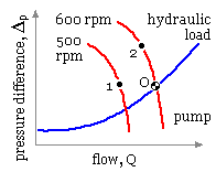
- A pump is analogous to a motor; its operating point 'O' when installed in an hydraulic load circuit is dictated by the intersection of the hydraulic (Q, Δp ) characteristics of pump and load as sketched. The approximate effect of speed on the pump characteristic is : flow ∝ speed, pressure difference ∝ speed2 , so the point '2' on the 600 rpm characteristic is related to the point '1' on the 500 rpm characteristic by Q2 = 1.2 Q1 , Δp2 = 1.22 Δp1
The load characteristic is concave upwards as it consists of two pressure difference components one of which (the static head) is constant while the other (the velocity or dynamic head) varies approximately as the square of the flow. These components depend upon physical attributes such as elevation differences, pipe diameters and lengths.
It follows that if the pump speed is less then 600 rpm then the flow through the hydraulic circuit would be reduced from that at 600 rpm. So the question of 'What speed is tolerable?'is really one of 'What flow is tolerable?'and we would need to know a lot more about the installation before such a question could be answered. A similar argument usually applies to ANY load on a motor, not just a pump.
- The full load speed of the 225 SMB motor is 1482 rpm, indicating a required speed reduction of 1482/600 = 2.47. The full load speed of the 250 SMA is the same, but it will be running light; so interpolating linearly between full load and synchronism, the speed when delivering 45.4 kW will be about 1500-(1500-1482)∗45.4/55 = 1485 rpm which corresponds to a required speed ratio of 1485/600 ≅ 2.47 also. So it is concluded that a 2.47:1 speed reducer is necessary with either motor.
But it would be fortuitous indeed if such an odd ratio were available off-the-shelf. If a more likely 2.5:1 unit were used then the motor demand would be reduced - as the pump speed would be 1482/2.5 = 593 rpm and from the scaling laws Pmotor = 45.4∗(593/600)3 = 43.8 < 45 kW, so the smaller 225 SMB is adequate.
It is unlikely that any of the preceding arguments can be firmed up by striving for greater precision in pump and reducer efficiencies, more exact scaling laws etc. We have to resign ourselves to arguments based upon imprecise/incomplete knowledge. It is for this reason that we may include suitable design factors (ie. factors of ignorance) to ensure that a critical installation is not compromised if operational parameters assume values at the dangerous end of their tolerance band. If the present installation is critical then we might select a 20% over-design and specify a required motor power of 1.2∗45.4 = 54.5 kW, necessitating the 250 SMA motor.
Good design requires accurate knowledge of the the physical units and processes, enabling minimisation of factors of ignorance and hence minimisation of over-design. But does the effort outweigh the cost?
In conclusion - based on the information supplied and pending further investigation - adopt the smaller 225 SMB motor with a 2.5:1 speed reducer.
 Copyright 1999-2005 Douglas Wright,
doug@mech.uwa.edu.au
last updated May 2005


