EXAMPLE
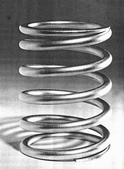
Estimate the stiffness and maximum operating stress of the close coiled steel spring with squared and ground ends illustrated.
The wire diameter d = 4 mm and the external diameter Do = 30 mm, so the mean coil diameter D = Do - d = 26 mm and the index is C = D/d = 6.5
Stress factors from ( 1) are Ks = 1+0.5/C = 1.08; Kh = (C+0.6)/(C-0.67) = 1.22
The total number of turns is now counted. This is a somewhat inaccurate process if the spring cannot be inspected physically. The leftmost coil here ends in a feather edge at the top, and so the end of the wire (imagined before grinding) must coincide with the vertical plane which contains the spring axis. Starting to count from this vertical plane - following the wire around towards the observer, then downwards, around the back and upwards to meet the plane again at the point 'a' illustrated - 'a' therefore corresponds to one complete turn.

Repeating this, we arrive at point 'b' after 11 complete turns. Continuing from 'b', the bottom is reached (another half turn) without the wire yet ground to a feather edge. So the wire must end at about 3/4 turn after 'b', therefore nt ≈ 113/4 turns. Ends are not ground right down to feather edges in practice, as shown by this cadmium plated hydraulic valve return spring.
From Table 1 the active turns are na = nt -2 = 93/4; the solid length is Ls = ntd = 47 mm, and the pitch is p = ( Lo -2d)/na = ( 85 -8)/93/4 = 7.9 mm. The corresponding helix angle is α = arctan( p/D) = 5.5o - the spring is certainly close coiled.
From ( 2) : k = Gd /8 naC3 = 79E3 x 4 / 8 x 9.75 x 6.53 = 14.8 N/mm
The solid deflection δs = Lo -Ls = 38 mm, so the solidification load is Fs = k δs = 14.8 x 38 = 560 N.
Assuming that solidification is infrequent and outside the working range, then this load will be treated as static so that the direct shear stress factor Ks applies in ( 1). The corresponding solid shear stress from ( 1) is therefore :
τs = Ks 8 FsC / π d2 = 1.08 x 8 x 560 x 6.5 / π 42 = 625 MPa.
Assume that at the maximum working state the above- mentioned 10% minimum clash allowance applies, so that δs - δhi ≥ 0.1 δhi ie. δhi ≤ δs/1.1 = 38/1.1 say δhi = 34 mm.
Proceeding as with the solid state, Fhi = k δhi = 14.8 x 34 = 505 N and so :
τhi = Ks 8 Fhi C / πd2 = 1.08 x 8 x 505 x 6.5 /π 42 = 563 MPa - static conditions still assumed.
Considering stability at this maximum state and assuming hinged ends (λ = 1), then λ Lo/c2D = 1 x 85 /2.62 x 26 = 1.25. Since this is greater than unity buckling could occur, so investigate via ( 3a):
δc = { 1 - √( 1 - 1/1.252 )} x 85/1.23 = 27 mm
and since the maximum deflection δhi exceeds δc then buckling will occur unless the spring is supported by a rod or surrounding cylinder. Alternatively if end rotation is prevented ( λ = 0.5) then λLo/c2D < 1 which automatically guarantees stability.
 Copyright 1999-2005 Douglas Wright,
doug@mech.uwa.edu.au
Copyright 1999-2005 Douglas Wright,
doug@mech.uwa.edu.au
last updated May 2005