Example
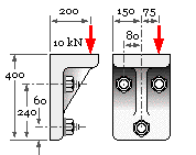
The bracket is fastened to a vertical support plane by three identical class 9.8 through-bolts, and supports the eccentric 10 kN steady load. Determine a suitable bolt size for a safety factor of 5.
Design load P = 5 x 10 = 50 kN
We shall examine this by means of different free bodies and related assumptions.
Free Body # 1 - the simplest FB, envisaging the bracket as a particle in side view.
 Contact with the vertical support plane is represented by the normal and friction components, N and Ff respectively. If breakaway is imminent and the bracket is equilibrated solely by friction and bolt tension, then :
Pbreakaway = Ff = μN = μ 3 Fi where Fi is the initial tightening load.
Assuming a typical friction coefficient of 0.35 and an initial tightening force of 90% proof then
Pbreakaway = 50 kN = 0.35 x 3 ( 0.9 x As x 650 ) ; As = 81 mm2 ie. M12 x 1.75 bolts are called for.

Free Body # 2 - side view.
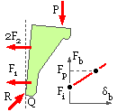
A more complex FBD of the side view recognises the non-particle nature of the bracket, which is assumed to be rigid and to rotate about the point Q where the support plane's concentrated reaction is R. The bolts deform ( δb ) beyond the initial state now that this rotational separation has occurred, so the forces in each of the two upper bolts F2 will be greater than the load in the lower bolt F1. Since the small opening angle = δ1/60 = δ2/240 it follows that δ2 = 4δ1 so that from the bolt characteristic ( F2 -Fi ) = 4( F1 -Fi).
For rotational equilibrium about the point Q :
60F1 + 240 x 2F2 = 200 x P which, using the above, gives 99F2 + 9Fi = 40P = 2000 kN
Assuming that the maximum bolt force F2 equals the proof load Fp at the design load P, and that the initial tightening load is 90% of proof, it follows that ( 99 + 9 x 0.9) As x 360 = 2 E6 N ; As = 52 mm2
So this model is by itself less critical than that of FB#1 in which total support is by friction - but this is not surprising because FB#2 says nothing about vertical equilibrium, assuming it to be achieved by the friction component of R at Q. Furthermore, the eccentricity of the load in the front view has not been addressed.

Free Body # 3 - front view
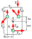
In this model the bracket is again presumed to be rigid, and equilibrium is taken to be achieved by shear of the bolt shanks, in a manner similar to sketch ( c) above. The centroid of the three equal shear areas A is located at G as shown. Since G does not lie on the line of action of the external load, a rotational tendency ( torsion ) exists.
Analysis is similar to the traditional analysis of fillet welds in that force equilibrium is achieved by uniform direct shear, while torsional equilibrium arises from secondary shear whose sense is perpendicular to the radius from the centroid to the location of the secondary shear, and which is proportional to that radius, given by the torsion equation
Ft = A τ = A ( T r/J ) = A Tr/Σ A r2 and since all A's are the same here Ft = Tr/Σ r2.
So the torsional shear forces are
Ft1 = ( P x 75) x 120/( 1202 + 2 ( 602 + 802 )) [ note units check ] = 90 P/344
Ft2 = Ft3 = Ft1 x 100/120 = 75 P/344.
The three equal direct shear forces equilibrate the force P, ie. F1d = F2d = F3d = P/3.
The bolt 2 is most critical since primary and secondary most nearly coincide in it. Combining these vectorially, the total shear force on the critical shank is F2 = 0.5243 P = 26.2 kN. Assuming the distortion energy failure theory, the proof strength in shear is 650/√3 = 375 MPa, so the required shank diameter is √(4 x 26200/ 375 π) = 9.4 mm ie. M10 is adequate. But of course this neglects friction and the prying action recognised by FB #2.
Free Bodies # 2 & 3
Combining the above, a conservative design approach assumes the support plane to be completely smooth, so that vertical equilibrium is achieved by shank shear, and R at Q is normal to the support plane.
From FB #2 assuming Fi ≈ F2 : tensile F2 = 2000/( 99+9) = 18.5 kN and so σ = 18.5 /A
From FB #3 : shear F2 = 26.2 kN and so τ = 26.2/A
Applying Mohr's circle and the maximum shear
 stress theory to this state ( σ,τ), the equivalent normal stress is σe = 2√( ( σ/2)2 +τ2 ) = 55.6/A from above, and = Sp at failure. So shank size = √( 4 x 55.6E3 / 650 π ) = 10.4 mm. So use M12x1.75 bolts.
It is fortuitous that the solution from this model is the same as that from FB #1.
Clearly the assumptions here are rather unrealistic - a completely rigid bracket, accurately located bolt holes ensuring theoretical sharing of shear, and so on. Anyhow, we would probably use larger bolts which 'looked right'!
 Copyright 1999-2005 Douglas Wright,
doug@mech.uwa.edu.au
last updated May 2005
 Contact with the vertical support plane is represented by the normal and friction components, N and Ff respectively. If breakaway is imminent and the bracket is equilibrated solely by friction and bolt tension, then :


 stress theory to this state ( σ,τ), the equivalent normal stress is σe = 2√( ( σ/2)2 +τ2 ) = 55.6/A from above, and = Sp at failure. So shank size = √( 4 x 55.6E3 / 650 π ) = 10.4 mm. So use M12x1.75 bolts.