Appendix : the compliant joint
 The force P is transmitted from member A to member B through the connector C of length L, which may be an adhesive or longitudinal fillet welds for example. Examination of the force transfer through the connection is a necessary precursor to the determination of the joint's safety.
A simple model of the system is considered in which the members A and B are taken to be in tension only, and C is in shear only. Load transfer between the members and the connector is by shear. There are two extremes of behaviour which may be appreciated qualitatively :-
- if the members are rigid and the connector is flexible, then the force is transferred uniformly, the connector is sheared uniformly and connector stresses are the lowest possible;
- if the members are very compliant and the connector is rigid, then neither member will deform substantially in way of the connector. This means that nearly all the force is transferred between A and C at x = L, and between B and C at x =0, leading to high stress concentrations at the ends of the joint.
The problem is a limiting continuous case of the multiple discrete connector assemblies examined previously in the Appendix to the chapter on Stress, Strength and Safety.
 It is statically indeterminate and so compatibility, equilibrium and the individual constitutive laws have to be examined.
- Compatibility
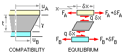
- Let uA and uB be the deflections of A and B from their unloaded positions at location x along the joint, and let γ be the shear strain in C. Geometry requires :
εA = duA /dx ; εB = duB /dx ; γ = ( uA - uB ) /t
- Equilibrium
- If q is the force intensity (force per unit length) on the element δx at x, then equilibrium requires that:
q = dFA /dx = - dFB /dx
- Constitutive Laws
- Assuming elastic behaviour :-
εA = ( σ/E )A = ( F/AE )A ;
εB = ( F/AE )B ;
γ = τ/GC = q/bGC
Eliminating the three strains and two deflections from the constitutive laws and compatibility; and defining the stiffnesses kA = (AE)A/L ; kB = (AE)B/L ; kC = bLGC /t leads to :-
dq/dx = ( FA /kA - FB /kB ) kC /L2
Solving the three simultaneous differential equations (this last together with the two equilibrium equations) for q, FA and FB , with boundary conditions FA = 0 at x = 0 and FA = P at x = L :-
qL/P = [ μ coshλφ + ( 1-μ ) coshλ( 1-φ ) ] λ / sinh λ
FA /P = 1 - FB /P = 1 - μ + [ μ sinhλφ - ( 1-μ ) sinhλ( 1-φ ) ] / sinh λ
in which φ = x/L ( 0 < = φ < = 1 ) is the normalised location along the joint, and both
λ = √( kC /kA + kC /kB ) and μ = 1/( 1 + kA /kB )
are constant parameters which are characteristic of the joint and determine its behaviour.
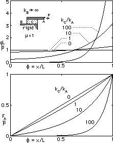
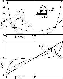
These results are plotted below for two different arrangements - on the left, one member is much less compliant than the other; on the right, the connected members are identical.
The upper graphs show how the force intensity q, and hence shear stress τ in the connector, vary along the joint. The lower figures illustrate the tension variation along member A. Although this model joint is a gross simplification, the trends portrayed by it are quite realistic and tally with the qualitative conclusions above - if the joined members are rigid and the connector C alone is compliant, then there is no stress concentration. The traditional/unified fillet models examined above are assumed to behave in just this ideal manner, so the models will underestimate the stresses which occur in practice.
 Copyright 1999-2005 Douglas Wright,
doug@mech.uwa.edu.au
last updated May 2005


 The force P is transmitted from member A to member B through the connector C of length L, which may be an adhesive or longitudinal fillet welds for example. Examination of the force transfer through the connection is a necessary precursor to the determination of the joint's safety.
 It is statically indeterminate and so compatibility, equilibrium and the individual constitutive laws have to be examined.

