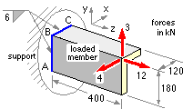
EXAMPLE

Geometric properties of the run :-
b = 120 d = 180 L = 300 mm
The centroid is located via the above table of run properties.
B lies at ( -24, 54, 0 ) mm in the centroidal system, and
Ixx = d3 (4b+d)/12L = 1.0692 E6 mm3 - note the units
Iyy = b3 (4d+b)/12L = 0.4032 E6 mm3 - hence Jzz = Ixx + Iyy = 1.4724 E6 mm3
Ixy = b2 d2 /4L = 0.3888 E6 mm3 - but this is not used in the traditional approach
Centroidal loading :-
The known loads on the loaded member are transferred to the run centroid, with introduction of the requisite moments. It is clear by inspection here that the resultant centroidal force is F = [ -4 3 12 ]' kN using the given Cartesian system. The resultant moment may be found either from three orthogonal views or by vector algebra.
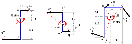
The three views are shown here, one moment component being ascertained by the RH rule from each view :
| view direction | positive x | negative y | negative z |
| diagram showing loads' moment about centroid | 
| ||
| centroidal load, kN | Fy = 3 ; Fz = 12 | Fx = -4 ; Fz = 12 | Fx = -4 ; Fy = 3 |
| moment of load about centroid (RH Rule), Nm | Mx = 12*54 -3*400 = -552 | My = 12*24 -4*400 = -1312 | Mz = 4*54 -3*24 = +144 |
Intensity components at line segment end-points for equilibrium :-
Primary : qp = -F/L = [ 4 -3 -12 ]' x 103 /300 = [ 13.3 -10 -40 ]' N/mm
| view direction | positive x | negative y | negative z |
| Secondary : diagram showing sense of secondary intensity to equilibrate centroidal moment | 
| ||
| out-of-plane bending | out-of-plane bending | in-plane torsion | |
| formula - check units | qx = Mx y / Ixx | qy = My x / Iyy | qz = Mz r / Jzz |
| intensity component at A (magnitude from formula; sign by inspection), N/mm | qxA= -552*126/1.0692= -65.1 | qyA= 1312*24/0.4032= +78.1 | qzxA= -144*126/1.4724= -12.3
qzyA= 144*24/1.4724= +2.4 |
| . . . and at B, N/mm | qxB = +27.9 | qyB = +78.1 | qzxB = +5.3
qzyB = +2.4 |
| . . . and at C, N/mm | qxC = +27.9 | qyC = -312.4 | qzxC = +5.3
qzyC= -9.4 |
Resultants :-
The resultant intensity at each point is the sum of all components, primary and secondary :-
qA = [ ( 13.3 -12.3 ) (-10.0 +2.4 ) ( -40.0 -65.1 +78.1 )]' = [ 1.0 -7.6 -27.0 ]' N/mm
qB = [ ( 13.3 +5.3 ) (-10.0 +2.4 ) ( -40.0 +27.9 +78.1 )]' = [ 18.6 -7.6 66.0 ]' N/mm
qC = [ ( 13.3 +5.3 ) (-10.0 -9.4 ) ( -40.0 +27.9-312.4)]' = [ 18.6 -19.4 -324.5 ]' N/mm
The problem is not pursued any further, to ascertain safety for example, because the numerical values are WRONG - the traditional approach does not cater for asymmetric bending which occurred in this example run. Although Ixy was evaluated, it was not used.